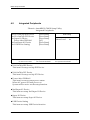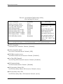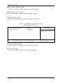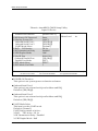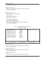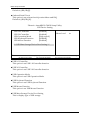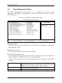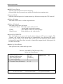
1
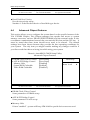
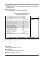
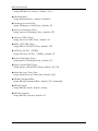
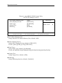
FEB-7100
Mini-ITX
Industrial Motherboard
User's Manual
Revision 1.00
Copyright © AICTEK Co., Ltd., 2008. All rights reserved.
All other brand names are registered trademarks of their respective owners.
Preface
Table of Contents
How to Use This Manual
Chapter 1 System Overview ....................................................................................................... 1-1
1.1 Introduction ....................................................................................................... 1-1
1.2 Check List ........................................................................................................... 1-2
1.3 Product Specification ........................................................................................ 1-2
1.4 System Architecture.......................................................................................... 1-5
Chapter 2 Hardware Configuration ........................................................................................... 2-1
2.1 Jumper Setting ................................................................................................... 2-1
2.1.1 Jumper Allocation .................................................................................... 2-1
2.1.2 Jumper Function List: .............................................................................. 2-2
2.1.3 Jumper Setting .......................................................................................... 2-2
2.2 Connector Allocation ........................................................................................ 2-4
2.2.1 Connector Function List: ......................................................................... 2-5
2.2.2 Pin Assignments:...................................................................................... 2-6
Chapter 3 System Installation .................................................................................................... 3-1
3.1 Main Memory .................................................................................................... 3-1
3.2 Installing the Embedded Board Computer ................................................... 3-1
3.2.1 Chipset Component Driver .................................................................... 3-2
3.2.2 VIA CX700M Graphics Controller ......................................................... 3-2
3.2.3 On-Board USB 2.0 .................................................................................... 3-2
3.3 Clear CMOS Operation .................................................................................... 3-2
3.4 WDT Function ................................................................................................... 3-3
3.4.1 WDT Programming Guide ..................................................................... 3-3
3.5 SMBus ................................................................................................................. 3-4
3.6 Display Output .................................................................................................. 3-4
3.7 GPIO.................................................................................................................... 3-5
3.7.1 Pin assignment ......................................................................................... 3-5
3.7.2 FEB-7100 GPIO Programming Guide ................................................... 3-5
Chapter 4 BIOS Setup Information ............................................................................................ 4-1
Entering Setup ....................................................................................... 4-1
4.1 Main Menu ......................................................................................................... 4-2
4.2 Standard CMOS Setup Menu .......................................................................... 4-4
4.3 Advanced BIOS Features ................................................................................. 4-6
4.4 Advanced Chipset Features............................................................................. 4-9
4.5 Integrated Peripherals .................................................................................... 4-13
4.6 Power Management Setup............................................................................. 4-19
4.7 PnP/PCI Configurations................................................................................ 4-21
4.8 PC Health Status ............................................................................................. 4-23
4.9 Frequency/Voltage Control .......................................................................... 4-24
4.10 Default Menu ................................................................................................. 4-24
Preface
4.11 Supervisor/User Password Setting ............................................................ 4-25
4.12 Exiting Selection ............................................................................................ 4-26
Chapter 5 Troubleshooting ........................................................................................................ 5-1
5.1 Hardware Quick Installation ........................................................................... 5-1
5.2 BIOS Setting ....................................................................................................... 5-2
5.3 FAQ ..................................................................................................................... 5-3
Preface
How to Use This Manual
The manual describes how to configure your FEB-7100 series system to meet various
operating requirements. It is divided into five chapters, with each chapter
addressing a basic concept and operation of Single Board Computer.
Chapter 1: System Overview. Presents what you have in the box and give you an
overview of the product specifications and basic system architecture for this series
model of single board computer.
Chapter 2: Hardware Configuration. To shows the definitions and locations of
Jumpers and Connectors that you can easily configure your system.
Chapter 3: System Installation. Describes how to properly mount the CPU, main
memory and Compact Flash to get a safe installation and provides a programming
guide of Watch Dog Timer function.
Chapter 4: BIOS Setup Information. Specifies the meaning of each setup
parameters, how to get advanced BIOS performance and update new BIOS. In
addition, POST checkpoint list will give users some guidelines of trouble-shooting.
Chapter 5: Troubleshooting. Provide various useful tips to quickly get FEB-7100
series running with success. As basic hardware installation has been addressed in
Chapter 3, this chapter will basically focus on system integration issues, in terms of
backplane/riser card setup, BIOS setting, and OS diagnostics.
The content of this manual and EC declaration document is subject to change
without prior notice. These changes will be incorporated in new editions of the
document.
System Overview
Chapter 1
System Overview
1.1
Introduction
FEB-7100 is a newly designed supporting VIA CX700M with high performance and
high integration computing platform. It is positioned at innovation, high integration
and high quality Embedded System Board in the embedded computing market.
The board is based on VIACX700M chipset and supports 800/400 Mhz C7 Processor,
chipset that support high speed DDR II SDRAM, high-performance graphic
controller with dual display/Panel and fast Ethernet connection. The on-board two
SATA ports and one IDE interface; Super I/O Chipset integrates six serial ports, one
keyboard controller, hardware monitoring and one parallel port. Besides, six USB
(Universal Serial Bus) ports provide high-speed data communication between
peripherals and PC. FEB-7100 series can provide most versatile Embedded System
Board (ESB) functionality in the market.
All in all, FEB-7100 series are designed to meet all kinds of embedded computing
application. With VIA most advance mainstream chipset for CX700M, FEB-7100 is
aiming at the most wide range of multimedia and networking applications in the
market.
Its compact design with standard Mini-ITX form factor makes it the most favorable
solution for high-density server. High reliability, compact size and easy-to-use
features fulfill the demand for critical embedded application including ATM, Kiosk,
POS, gaming and medical equipment... ,etc.
Key Features:
Mini-ITX form factor to fit in most wide range of system architecture
VIA new generation chipset VIA CX700M powered by C7 processor,
Dual independent on-board display support CRT, LVDS
On-board standard I/O, dual display, panel option, network and audio to meet
the requirements of communication and multimedia platforms
z On-board 10/100BASE-TX Ethernet
z Up to 2GB high performance 240 pin DIMM DDR II SDRAM allows to run
versatile embedded programs
z
z
z
z
FEB-7100 User’s Manual
1-1
System Overview
1.2
Check List
The FEB-7100 package should cover the following basic items:
9
9
9
9
9
9
FEB-7100 Mini-ITX Industrial Motherboard x 1
Installation Resources CD-Title x 1
Internal Serial Port Cable (option)
Internal USB Cable (option)
SATA HDD Cable (option)
IDE 44 pins to 80 pins HDD Cable (option)
If any of these items is damaged or missing, please contact your vendor and keep all
packing materials for future replacement and maintenance.
1.3
Product Specification
z Processor
¾ Support 800/400MHz VIA C7 Processor
¾ L2 Cache built-in
z Chipset
¾ VIA CX700M Integrated UniChrome Pro II 3D / 2D Graphics & Video
Processor Unified Video Decoding Accelerator Integrated and LVDS
Transmitter
¾ Winbond W83627EHG Super I/O Controller.
z System Memory
¾ Two 240 pin DDR II socket
¾ Support DDR II SDRAM 400/533MHz up to 2GB.
Supports 64Mb / 128Mb / 256Mb / 512Mb (x8 / x16 / x32)
Supports 1Gb (x16)
z On-board VGA
¾ CX700M Integrated 3D / 2D / Video Processors
¾ Pixel resolution Up to 1920x1400
¾ Support D-Sub 15Pin connector.
z On-board LVDS
¾ CX700M Integrated 3D / 2D / Video Processors
¾ Panel support Up to 1600x1200 (UXGA)
¾ Support Single and Dual (18bit/24bit) LVDS output.
FEB-7100 User’s Manual
1-2
System Overview
z Ethernet
¾ Realtek RTL8100C 10/100M Base-T Ethernet Controller.
¾ Support Boot-on-LAN function.
¾ Support Wake-on-LAN function.
¾ Support RJ45 Jack connector.
z Audio
¾ VIA VT1708B HD Audio CODEC.
¾ Support Line-Out with Phone Jack.
¾ Support 6W Amplified stereo output with Wafer Header
z SATA Interface
¾ CX700M Integrated Serial ATA Host Controller
¾ Support two Serial ATA ports, data transfer rates up to 3.0 Gb/s (300 MB/s)
z IDE Interface
¾ Support Ultra ATA 33/66/100, BMIDE and PIO modes.
¾ One 2.0mm pitch 2x22pin IDE connector shares the secondary IDE channel
with Compact Flash socket.
z USB Interface
¾ Support six ports for high-speed I/O peripheral devices
z Serial Ports
¾ Support six ports high-speed 16C550 compatible UARTs with 16-byte T/R
FIFOs.
z Parallel Port
¾ Support one parallel port with SPP, EPP and ECP modes.
¾ Support D-Sub 25Pin connector.
z PS/2 Mouse and Keyboard Interface
¾ Support one PS/2 Keyboard and Mouse with mini-DIN connector.
z Real Time Clock/Calendar (RTC)
¾ Support Y2K Real Time Clock/Calendar with battery backup for 5-year data
retention.
z Watchdog Timer
¾ Support software programming for enable/disable and interval setting.
¾ Generate system reset from 1sec/min to 255sec/min.
z High Driving GPIO
FEB-7100 User’s Manual
1-3
System Overview
¾ Support 5 high driving capabilities for GPIO (2 GPI and 3 GPO)
¾ Support RJ11 connector for 1 GPI and 2 GPO (Support +12V device)
¾ Support Pin Header for 1 GPI and 1 GPO
z Cooling Fans
¾ Support two 3-pin headers for CPU and System Fans.
¾ Support Smart-Fan mode function.(option)
z System Monitoring Feature
¾ Monitor CPU temperature, system temperature and major power sources,
etc.
z Power Management
¾ Support ACPI 2.0 APM V1.2 Compliant
¾ Support for APM-based legacy power management
z Operating Temperature: -5°C ~ 60°C (23°F ~ 140°F)
z Storage Temperature: -20°C ~ 80°C
z Relative Humidity: 0% ~ 95%, non-condensing
z Relative Humidity: 0% ~ 95%, non-condensing
z Board Dimension (L*W): 170x170 mm
FEB-7100 User’s Manual
1-4
System Overview
1.4
System Architecture
The most up-to-date system architecture of FEB-7100 includes VIA CX700M chip,
supports VIA 800/400 MHz C7 processor, DDR II SDRAM, 2D/3D graphic display,
and supports SATA interface,ACPI compliant power management, USB port, SMBus
communication, and Ultra DMA/33/66/100 IDE Master. W83627EHG (I/O
Controller) is responsible for PS/2 Keyboard/Mouse, UARTs, Hardware Monitor,
Parallel, Watchdog Timer, GPIO interface. And the F81216D supports four UARTs.
FEB-7100 User’s Manual
1-5
Hardware Configuration
Chapter 2 Hardware Configuration
This chapter gives the definitions and shows the positions of jumpers, headers and
connector. All of the configuration jumpers of FEB-7100 are in the proper position.
The default settings shipped from factory are marked with a star (Ì).
2.1Jumper Setting
For users to customize FEB-7100’s features, in the following sections, Short means
covering a jumper cap over jumper pins; Open or N/C (Not Connected) means
removing a jumper cap from jumper pins. User can refer to Figure 2-1 for the Jumper
locations.
2.1.1Jumper Allocation
FEB-7100 User’s Manual
2-1
Hardware Configuration
2.1.2Jumper Function List:
Jumper
JP1
JP2
JP3
JP4
JP5
JP6
JP7
JP9
JP10
JP11
Function
COM4 Mode Selection
CMOS Clear
COM3 RI function Selection
COM4 RI function Selection
Compact Flash Master/Slave Selection
COM6 RI function Selection
Panel Mode Selection
COM5 RI function Selection
COM2 RI function Selection
COM5 Mode Selection
JP12
COM1 RI function Selection
Remark
2.1.3Jumper Setting
JP1: COM4 Mode Selection
JP1
1-2, 3-4 short
1-2, 3-4 open
Mode
VFD Mode
RS-232 Mode Ì
JP2: CMOS Clear
JP2
1-2 Short
2-3 Short
Function
Normal Operation Ì
Clear CMOS Contents
JP3: COM3 RI function Selection
JP3
1-2 short
3-4 short
5-6 short
Function
+5V Ì
Ring In
+12V
FEB-7100 User’s Manual
2-2
Hardware Configuration
JP4: COM4 RI function Selection
JP4
1-2 short
3-4 short
5-6 short
Function
+5V Ì
Ring In
+12V
JP5: Compact Flash Master/Slave Selection
JP5
1-2
2-3
Function
Compact Flash set to master on IDE secondary channel
(share secondary IDE channel with 44 pin IDE connector).
Compact Flash set to slave on IDE secondary channel Ì
(share secondary IDE channel with 44 pin IDE connector).
JP6: COM6 RI function Selection
JP6
1-2 short
3-4 short
5-6 short
Function
+5V
Ring In Ì
+12V
JP7: Panel Mode Selection
JP7
1-2 short
2-3 short
Mode
High
Low Ì
JP9: COM5 RI function Selection
JP9
1-2 short
3-4 short
5-6 short
Function
+5V
Ring In Ì
+12V
FEB-7100 User’s Manual
2-3
Hardware Configuration
JP10: COM2 RI function Selection
JP10
1-2 short
3-4 short
5-6 short
Function
+5V
Ring In Ì
+12V
JP11: COM5 Mode Selection
JP11
1-2, 3-5, 4-6 short
1-3, 2-4 short
Mode
VFD Mode
RS-232 ModeÌ
JP12: COM1 RI function Selection
JP12
1-2 short
3-4 short
5-6 short
Function
+5V
Ring In Ì
+12V
2.2Connector Allocation
FEB-7100 User’s Manual
2-4
Hardware Configuration
2.2.1Connector Function List:
Connector
Audio1
Audio2
SYSFAN1, CPUFAN1
Cash_Drawer1
CF1
COM 2
COM 1,3, 4, 6
COM 5
DIO1
KB_MS
Function
Line-out with Phone Jack
Speaker out Connector
Fan 3Pin Connectors
Digital I/O with RJ-11 Connector
Compact Flash Connector
Serial port with D-sub 9Pin
Serial port with Wafer Connectors
Serial port with RJ45 Connectors
Digital I/O with 2Pin Connector
PS2 Keyboard & Mouse Connector
MCR1
External Keyboard Connector
INV1
LVDS Inverter Power Connector
LVDS1
JFront1
LVDS LCD Panel Connector
Front Panel Connector
FEB-7100 User’s Manual
Remark
2-5
Hardware Configuration
LAN
LPT
SATA1,SATA2
SATA_PWR1&2
J13
DC_IN12V
RJ45 LAN Connector
Parallel port with D-sub 25Pin
SATA Connector
SATA Power Connector
12V 2x2 Power Input Connector
12V DC Power Input Connector
DC_OUT12V
12V DC Power Output Jack
USB1,USB2
USB dual port Connectors
USB3,USB4
VGA1
USB port with Wafer Connectors
D-Sub15P CRT Connector
2.2.2Pin Assignments:
AUDIO1: Line-out with Audio Phone Jack
PIN No.
1
2
3
4
5
Signal Description
Audio Ground
Audio-out-L
Audio Ground
Jack Plugged detect
Audio-out-R
AUDIO2: Speaker Output with Wafer Connector (2.0mm)
PIN No.
1
2
3
4
Signal Description
Speaker output Right
Speaker Audio Ground
Speaker Audio Ground
Speaker output Left
CPUFAN1/SYSFAN1: Fan Connector
PIN No.
1
2
3
Signal Description
Ground
Fan Power (+12V)
Speed Sense
Cash_Drawer1: DIO with RJ-11 Connector
PIN No.
1
Signal Description
Ground
FEB-7100 User’s Manual
2-6
Hardware Configuration
2
3
4
5
6
DIO Out 0
DIO IN 0
+12V
DIO Out 1
Ground
CF1: Compact Flash Connector
PIN No.
1
2
3
4
5
6
7
8
9
10
11
12
13
14
15
16
17
18
19
20
21
22
23
24
25
Signal Description
Ground
Data 3
Data 4
Data 5
Data 6
Data 7
Select 0
Ground
Ground
Ground
Ground
Ground
+5V
Ground
Ground
Ground
Ground
SA2
SA1
SA0
Data 0
Data 1
Data 2
Pull Up to +5V
Ground
PIN No.
26
27
28
29
30
31
32
33
34
35
36
37
38
39
40
41
42
43
44
45
46
47
48
49
50
Signal Description
Ground
Data 11
Data 12
Data 13
Data 14
Data 15
Select 1
N/C
IO Read
IO Write
Pull Up to +5V
IRQ 15
+5V
Slave/Master# Select
N/C
Reset
IORDY
DMA REQ
DMA ACK#
IDE Active
Pull Up to +5V
Data 8
Data 9
Data 10
Ground
COM2: Serial Port 1/2 Connector with D-Sub9P
PIN No.
1
2
3
4
Signal Description
DCD
RXD
TXD
DTR
FEB-7100 User’s Manual
PIN No.
6
7
8
9
Signal Description
DSR
RTS
CTS
RI /+12V/+5V
2-7
Hardware Configuration
5
Ground
10
NC
COM1/COM3/COM4/COM6: Serial port with Wafer Connectors (2.0mm)
PIN No.
1
3
5
7
9
Signal Description
DCD
RXD
TXD
DTR
Ground
PIN No.
2
4
6
8
10
Signal Description
DSR
RTS
CTS
RI/+5V/+12V
RI/+5V/+12V
DIO1: DIO Connector with Pin Header (2.54mm)
PIN No.
1
2
Signal Description
DIO-In
DIO-Out
KB/MS: PS2 Keyboard & Mouse with Mini-DIN Connector
PIN No.
1
3
5
Signal Description
KBDATA
Ground
KBCLK
PIN No.
2
4
6
Signal Description
MSDATA
+5V
MSCLK
MCR1: Internal Keyboard with Wafer Connector (2.0mm)
PIN No.
1
3
5
Signal Description
+V5
KCLK_KBC
KDAT_KBC
PIN No.
2
4
6
Signal Description
KCLK_CON
KDAT_CON
Ground
INV1: Panel Inverter Power with Wafer Connector (2.5mm)
PIN No.
1
2
3
4
5
Signal Description
+12V
+12V
Ground
Ground
Back Light Enable
FEB-7100 User’s Manual
2-8
Hardware Configuration
LVDS1: LVDS Panel Signals With Wafer Connector (1.0mm)
PIN No.
1
3
5
7
9
11
13
15
17
19
21
23
25
27
29
Signal Description
Ground
Data A3+
Clock A+
Data A2+
Data A1+
Data A0+
Ground
Data B3+
Clock B+
Data B2+
Data B1+
Data B0+
Ground
LVDS VDD
LVDS VDD
PIN No.
2
4
6
8
10
12
14
16
18
20
22
24
26
28
30
Signal Description
Ground
Data A3Clock AData A2Data A1Data A0Ground
Data B3Clock BData B2Data B1Data B0Ground
LVDS VDD
Panel Bit Select
PIN No.
2
4
6
8
10
Signal Description
5VSB LED
Power switch
LAN TX/RX LED
HDD LED
Reset Switch
JFRONT1: Front Panel Connector (2.0mm)
PIN No.
1
3
5
7
9
Signal Description
Power LED
Ground
5VSB (470 Ohm)
+5V (470 Ohm)
Ground
LPT: Parallel Port Connector with D-Sub25P
PIN No.
1
2
3
4
5
6
7
8
9
10
11
12
13
Signal Description
Strobe#
Data 0
Data 1
Data 2
Data 3
Data 4
Data 5
Data 6
Data 7
Acknowledge#
Busy
Paper Empty
Printer Select
FEB-7100 User’s Manual
PIN No.
14
15
16
17
18
19
20
21
22
23
24
25
Signal Description
Auto Form Feed#
Error#
Initialization#
Printer Select IN#
Ground
Ground
Ground
Ground
Ground
Ground
Ground
Ground
2-9
Hardware Configuration
SATA1/2: SATA Connector
PIN No.
1
2
3
4
5
6
7
Signal Description
Ground
TXD+
TXDGround
RXDRXD+
Ground
SATA_PWR1&2: SATA Power with Wafer Connector (2.0mm)
PIN No.
1
2
3
4
5
6
Signal Description
+5V
+5V
Ground
Ground
+12V
+12V
J13: 12V 2x2 Power Input Connector (4.2mm)
PIN No.
1
2
3
4
Signal Description
Ground
Ground
+12V DC-In
+12V DC-In
DC_IN12V:12V DC Power Input Connector
PIN No.
1
2
3
4
Signal Description
+12V DC-In
Ground
+12V DC-In
Ground
FEB-7100 User’s Manual
2-10
Hardware Configuration
DC_OUT12V:12V DC Power Input Jack
PIN No.
1
2
3
Signal Description
+12V DC-In
Ground
Ground
USB_LAN: USB 1/2 & LAN Connector with Dual USB& Ethernet RJ-45
PIN No.
U1
U2
U3
U4
L1
L2
L3
L4
Signal Description
+5V
USBDATA0USBDATA0+
Ground
TXD+
TXDRXD+
NC
PIN No.
U5
U6
U7
U8
L5
L6
L7
L8
Signal Description
+5V
USBDATA1USBDATA1+
Ground
NC
RXDNC
NC
USB2_COM5: USB 3/4 Connector & COM5 with Dual USB& RJ-45
PIN No.
U1
U2
U3
U4
L1
L2
L3
L4
Signal Description
+5V
USBDATA2USBDATA2+
Ground
RI/+5V/+12V
CTS/+5V/+12V
Ground
RTS/ Ground
PIN No.
U5
U6
U7
U8
L5
L6
L7
L8
Signal Description
+5V
USBDATA3USBDATA3+
Ground
DTR
DSR
TXD
RXD
USB: USB1/2 Ports with Wafer Connector (2.0mm)
PIN No.
1
3
5
7
Signal Description
USB +5V
USBDATAUSBDATA+
USB Ground
FEB-7100 User’s Manual
2-11
Hardware Configuration
VGA: CRT Connector with D-Sub15P
PIN No.
1
3
5
7
9
11
13
15
Signal Description
RED
BLUE
Ground
Ground
CRT Power (+5V)
ID1
HSYNC
DDCCLK
FEB-7100 User’s Manual
PIN No.
2
4
6
8
10
12
14
Signal Description
GREEN
ID0
Ground
Ground
Ground
DDCDATA
VSYNC
2-12
System Installation
Chapter 3 System Installation
This chapter provides you with instructions to set up your system. The additional
information is enclosed to help you set up onboard device and handle WDT
operation in software programming.
3.1
Main Memory
FEB-7100 provides two DDR II-SDRAM DIMM slots to support 1.8V DDR IISDRAM as on-board main memory. The maximum memory size can be up to 2GB.
And auto detecting memory clock according to BIOS CMOS settings.
Watch out the contact and lock integrity of memory module with socket, it will
impact on the system reliability. Follow normal procedures to install your DRAM
module into memory socket. Before locking, make sure that all modules have been
fully inserted into the card slots.
Note:
To maintain system stability, don’t change any of DRAM parameters in BIOS setup
to upgrade your system performance without acquiring technical information.
3.2
Installing the Embedded Board Computer
To install your FEB-7100 into standard chassis or proprietary environment, you need
to perform the following:
Step 1: Check all jumpers setting on proper position
Step 2: Install and configure CPU and memory module on right position
Step 3: Place FEB-7100 into the dedicated position in your system
Step 4: Attach cables to existing peripheral devices and secure it
WARNING
Please ensure that your FEB-71000 is properly inserted and fixed by mechanism.
Note:
Please refer to section 3-4-1 to 3-4-5 to Chipset/VGA/LAN/Audio drivers.
FEB-7100 User’s Manual
3-1
System Installation
3.2.1
Chipset Component Driver
VIA CX700M chipset is a new chipset that a few old operating systems might not be
able to recognize. To overcome this compatibility issue, for Windows Operating
Systems such as Windows 2000 / XP / 2003 / Vista, please Chipset Component
driver before any of other Drivers are installed.
3.2.2
VIA CX700M Graphics Controller
VIA CX700M integrated 200MHz, 128-bit UniChrome Pro II graphics processor is
implemented on Unified Memory Architecture with frame buffer size of up to
128MB. 32bpp color depth.
3.2.3
On-Board USB 2.0
FEB-7100 includes three UHCI host controllers that support six external ports, and
high-speed USB 2.0 Host Controller that supports all ports.
3.3
Clear CMOS Operation
The Clear CMOS operation is implemented if the system fails to start at least one
time.
The following table indicates how to enable/disable CMOS Clear Function hardware
circuit by putting jumpers at proper position.
JP2
1-2 Short
2-3 Short
Function
Normal Operation ★
Clear CMOS Contents
To correctly operate CMOS Clear function, users must turn off the system, move JP2
jumper to short pin 2 and 3. To clear CMOS, please turn the power back on and turn
it off again for AT system, or press the toggle switch a few times for ATX system.
Move the JP2 back to 1-2 position (Normal Operation) and start the system. System
will then produce a “CMOS Check Sum Error” message and hold up. Users may
then follow the displayed message to load BIOS default setting.
FEB-7100 User’s Manual
3-2
System Installation
3.4
WDT Function
The working algorithm of the WDT function can be simply described as a counting
process. The Time-Out Interval can be set through software programming. The
availability of the time-out interval settings by software or hardware varies from
boards to boards.
FEB-7100 allows users control WDT through dynamic software programming. The
WDT starts counting when it is activated. It sends out a signal to system reset or to
non-maskable interrupt (NMI), when time-out interval ends. To prevent the time-out
interval from running out, a re-trigger signal will need to be sent before the counting
reaches its end. This action will restart the counting process. A well-written WDT
program should keep the counting process running under normal condition. WDT
should never generate a system reset or NMI signal unless the system runs into
troubles.
The related Control Registers of WDT are all included in the following sample
program that is written in C language. User can fill a non-zero value into the Timeout Value Register to enable/refresh WDT. System will be reset after the Time-out
Value to be counted down to zero. Or user can directly fill a zero value into Time-out
Value Register to disable WDT immediately. To ensure a successful accessing to the
content of desired Control Register, the sequence of following program codes should
be step-by-step run again when each register is accessed.
Additionally, there are maximum 2 seconds of counting tolerance that should be
considered into user’ application program. For more information about WDT, please
refer to Winbond W83627EHG data sheet.
3.4.1
WDT Programming Guide
WDT Programming setting as below steps:
Step 1: CR2D, Bit0→0 (select pin77 to WDTO#)
Step 2: LD8, CR30, Bit0→1 (Active WDTO#)
Step 3: LD8, CRF7, Bit4→Write 0 to clear WDTO# status.
Step 4: LD8, CRF5, Bit3→0: Second mode, 1: Minute mode
Step 5:LD8, CRF6, Bit [7:0] →Set WDTO# Time out value. (WDTO# startup after
setting the system time, or setup from step 3 ~ step 5 to restart WDT.)
FEB-7100 User’s Manual
3-3
System Installation
3.5
SMBus
The CX700M provides an SMBus 2.0 compliant Host controller as well as an SMBus
Slave Interface. The Host controller provides a mechanism for the processor to
initiate communications with SMBus peripherals (slaves). The CX700M is also
capable of operating in a mode in which it can communicate with I2C compatible
devices.
The CX700M can perform SMBus messages with either packet error checking (PEC)
enabled or disabled. The actual PEC calculation and checking is performed in
hardware by the CX700M.
The System Management Bus is a two-wire interface through which simple power
related chips can communicate with rest of the system. It uses I2C as its backbone. A
system using SMBus passes messages to and from devices instead of tripping
individual control lines. With the SMBus, a device can provide manufacturer
information, tell the system what its model/part number is, save its state for a
suspend event, report different types of errors, accept control parameters, and return
its status
The SMBus may share the same host device and physical bus as ACCESS bus
components provided that an appropriate electrical bridge is provided between the
internal SMBus devices and external ACCESS bus devices
3.6
Display Output
VIA CX700M chipset is the result of new design approach to optimize the shared
memory architecture while maintaining the cost benefits of integration.
With no additional video adaptor, this onboard video will be the system display
output.
FEB-7100 User’s Manual
3-4
System Installation
3.7
GPIO
The FEB-7100 provides 1 input and 2 output ports that can be individually
configured to perform a simple basic I/O function. Users can configure each
individual port to become an input or output port by programming register bit of
I/O Selection. To invert port value, the setting of Inversion Register has to be made.
Port values can be set to read or write through Data Register.
3.7.1
Pin assignment
Cash_Drawer1: DIO with RJ-11 Connector
PIN No.
1
2
3
4
5
6
Signal Description
Ground
DIO-Out 0
DIO-In 0
+12V
DIO-Out 1
Ground
DIO1: DIO Connector with Pin Header (2.54mm)
PIN No.
1
2
3.7.2
Signal Description
DIO-In 3
DIO-Out 3
FEB-7100 GPIO Programming Guide
Access CASH_DRAWER1 GPIO port
There are two PNP I/O port addresses that can be used to configure GPIO ports,
1) 0x2E - EFER (Extended Function Enable Register, for entering Extended Function
Mode)
- EFIR (Extended Function Index Register, for identifying CR index number)
2) 0x2F - EFDR (Extended Function Data Register, for accessing desired CR)
Below are some example codes, which demonstrate the use of GPIOs.
FEB-7100 User’s Manual
3-5
System Installation
// Enter Extended Function Mode
outp(0x002E, 0x87);
outp(0x002E, 0x87);
// Assign Pin121-128 to be GPIO port 1
outp(0x002E, 0x29);
outp(0x002F, inp(0x002F) | 0x01);
// Select Logic Device 7
outp(0x002E, 0x07);
outp(0x002F, 0x07);
// Active Logic Device 7
outp(0x002E, 0x30);
outp(0x002F, 0x01);
// Select Inversion Mode
outp(0x002E, 0xF2);
outp(0x002F, 0x83);
// Select I/O Mode
// Bit0~bit3 output and bit4~bit7 input
outp(0x002E, 0xF1);
outp(0x002F, 0x00);
// Access GPIO ports
outp(0x002E, 0xF0);
outp(0x002F, 0x7C);
// Exit Extended Function Mode
outp(0x002E, 0xAA);
Definitions of Variables:
Each bit in the lower nibble of each Register represents the setting of a GPIO port.
Bit0 vs. GPIO DIO-Out 0
Bit1 vs. GPIO DIO-Out 1
Bit7 vs. GPIO DIO-Out 3
Bit4 vs. GPIO DIO-In 0
Bit3 vs. GPIO DIO-In 3
Value of Inversion Register:
Only lower nibble is available for this function.
When set to a ‘1’, the incoming/outgoing port value is inverted.
When set to a ‘0’, the incoming/outgoing port value is the same as in Data Register.
FEB-7100 User’s Manual
3-6
System Installation
Value of I/O Selection Register:
Only lower nibble is available for this function.
When set to a ‘1’, respective GPIO port is programmed as an input port.
When set to a ‘0’, respective GPIO port is programmed as an output port.
Value of Output Data / Input Data:
Only lower nibble is available for this function.
If a port is assigned to be an output port, then its respective bit can be read/write.
If a port is assigned to be an input port, then its respective bit can be read only.
Note:
Some other functions may occupy the high nibble of the registers. Altering any
content in high nibble will be undesired.
FEB-7100 User’s Manual
3-7
BIOS Setup Information
Chapter 4 BIOS Setup Information
FEB-7100 is equipped with the AWARD BIOS stored in FWH Flash ROM. These
BIOS has a built-in Setup program that allows users to modify the basic system
configuration easily. This type of information is stored in CMOS RAM so that it is
retained during power-off periods. When system is turned on, FEB-7100
communicates with peripheral devices and checks its hardware resources against the
configuration information stored in the CMOS memory. If any error is detected, or
the CMOS parameters need to be initially defined, the diagnostic program will
prompt the user to enter the SETUP program. Some errors are significant enough to
abort the start-up.
z
Entering Setup
Turn on or reboot the computer. When the message “Hit <DEL> if you want to run
SETUP” appears, press <Del> key immediately to enter BIOS setup program.
If the message disappears before you respond, but you still wish to enter Setup,
please restart the system to try “COLD START” again by turning it OFF and then
ON, or touch the "RESET" button. You may also restart from “WARM START” by
pressing <Ctrl>, <Alt>, and <Delete> keys simultaneously. If you do not press
the keys at the right time and the system will not boot, an error message will be
displayed and you will again be asked to,
Press <F1> to Run SETUP or Resume
In HIFLEX BIOS setup, you can use the keyboard to choose among options or
modify the system parameters to match the options with your system. The table
below will show you all of keystroke functions in BIOS setup.
↑↓→ ←
Enter
+ / - /PU /PD
ESC
F1
F2
F5
F6
F7
F9
F10
FEB-7100 User’s Manual
General Help
: Move
: Select
: Value
: Exit
: General Help
: Item Help
: Previous Values
: Fail-Safe Defaults
: Optimized Defaults
: Menu in BIOS
: Save
4-1
BIOS Setup Information
4.1 Main Menu
Once you enter FEB-7100 AWARD BIOS CMOS Setup Utility, you should start with
the Main Menu. The Main Menu allows you to select from fourteen setup functions
and two exit choices. Use arrow keys to switch among items and press <Enter> key
to accept or bring up the sub-menu.
Phoenix- AwardBIOS CMOS Setup Utility
f Standard CMOS Features
f Advanced BIOS Features
f Advanced Chipset Features
f Integrated Peripherals
f Power Management Setup
f PnP/PCI Configurations
f PC Health Status
fFrequency/Voltage Control
Load Fail-Safe Defaults
Load Optimized Defaults
Set Supervisor Password
Set User Password
Save & Exit Setup
Exit Without Saving
↑ ↓ → ← : Select Item
ESC : Quit
F10 : Save & Exit Setup
Time, Date, Hard Disk Type …
Note:
It is strongly recommended to reload Optimal Setting if CMOS is lost or BIOS is
updated.
Note:
It is strongly recommended to reload Optimal Setting if CMOS is lost or BIOS is
updated.
▲Standard CMOS Features
This setup includes SBC parameter as Time , Date , Hard Disk Type ……
▲Advanced BIOS Features
For choice special enhance feature .
▲Advanced Chipset Features
This setup include display and onboard device setup.
▲ Integrated Peripherals
This setup include on board peripheral setup.
▲Power Management Setup
This setup can be set SBC power management.
FEB-7100 User’s Manual
4-2
BIOS Setup Information
▲PnP/PCI Configurations
This setup can be set PCI configuration & resource..
▲PC Health Status
This setup can display SBC health state as voltage , board temperature … etc.
▲Frequency/Voltage Control
This setup can control CPU clock and frequency ratio.
▲Load Fail-Safe Defaults
This setup contain BIOS all item default setup in safe mode.
▲Load Optimized Default
This setup contain BIOS all item default setup in best performance mode.
▲Set Supervisor Password
Set password to allow access into the BIOS setup for supervisor.
▲Set User Password
This setup can set password to allow access into the BIOS limit setup.
▲Save & Exit Setup
Save BIOS setup value to CMOS and exit setup.
▲Exit Without Saving
Exit setup and keep last time setup value.
FEB-7100 User’s Manual
4-3
BIOS Setup Information
4.2
Standard CMOS Setup Menu
This setup page includes all the items in a standard compatible BIOS. Use the arrow
keys to highlight the item and then use the <PgUp>/<PgDn> or <+>/<-> keys to
select the value or number you want in each item and press <Enter> key to certify it.
Follow command keys in CMOS Setup table to change Date, Time, and IDE item.
Phoenix- AwardBIOS CMOS Setup Utility
Standard CMOS Features
Date (mm:dd:yy)
Time (hh:mm:ss)
f IDE Primary 0 Master
f IDE Primary 0 Slave
f IDE Secondary 1 Master
f IDE Secondary 1 Slave
Thu, Jul 6 2007
11 : 29 : 50
[HDS728080PLAT20]
[None]
[None]
[None]
Video
Halt On
[EVG/VGA]
[All, But Keyboard]
Base Memory
Extended Memory
Total Memory
640K
980992K
980992K
↑↓→←: Move
Enter: Select
F5: Previous Values
Item Help
Menu Level
f
Change the day, month,
year and century
+/-/PU/PD: Value
F10: Save
ESC: Exit
F1: General Help
F6: Fail-Safe Defaults
F7: Optimized Defaults
▲Date
The data format : [week],[month],[day],[year].
▲Time
The time format : [hour],[minute],[second].
▲IDE Primary 0 Master
Auto detect IDE device on channel 0,
Press “Enter” for automatic device detection.
▲IDE Primary 0 Slave
Auto detect IDE device on channel 0,
Press “Enter” for automatic device detection.
▲IDE Primary 1 Master
Auto detect IDE device on channel 1,
Press “Enter” for automatic device detection.
FEB-7100 User’s Manual
4-4
BIOS Setup Information
▲IDE Primary 1 Master
Auto detect IDE device on channel 1,
Press “Enter” for automatic device detection.
▲Video
Select the type of primary video subsystem in your computer. The BIOS usually
detects the correct video type automatically.
EGA/VGA
CGA40
CGA80
MONO
Enhance Graphics Adapter/Video Graphics Array.
For EGA, VGA, SEGA, SVGA or PGA monitor adapters.
Color Graphics Adapter, power up in 40 column mode.
Color Graphics Adapter, power up in 80 column mode.
Monochrome adapter, includes high resolution
monochrome adapters.
▲Halt On
During the power-on self-test(POST), the computer stops if the BIOS detects a
hardware error. You can tell the BIOS to ignore certain errors during POST and
continue the boot-up process. These are the selections:
No errors
All errors
POST does not stop for any errors.
If the BIOS detects any non-fatal error, POST stops and prompts
you to take corrective action.
All,
But keyboard POST does not stop for a keyboard error, but stops for all other
errors.
▲Base Memory
Typically 640 KB. Also called conventional memory. The DOS operating system
and conventional applications use this area.
▲Extended Memory
Above the 1-MB boundary. Early IBM personal computers could not use
memory above 1MB, but current PCs and their software can use extended
memory.
▲Total Memory
Total system memory available area.
FEB-7100 User’s Manual
4-5
BIOS Setup Information
4.3
Advanced BIOS Features
This section allows you to configure your system for basic operation. You have the
opportunity to select the system’s default speed, boot-up sequence, keyboard
operation, shadowing and security.
Phoenix- AwardBIOS CMOS Setup Utility
Advanced BIOS Features
►CPU Feature
►Hard Disk Boot Priority
Virus Warning
CPU L1 & L2 Cache
CPU L2 Cache ECC Checking
Quick Power On Self Test
First Boot Device
Second Boot Device
Third Boot Device
Boot Other Device
Boot up NumLock Status
Typematic Rate Setting
X Typematic Rate (Chars/sec)
X Typematic delay (Msec)
Security Option
MPS Version Control For OS
OS Select For DRAM > 64MB
Video BIOS Shadow
Small Logo(EPA) Show
↑↓→←: Move
Enter: Select
F5: Previous Values
[Press Enter]
[Press Enter]
[Disabled]
[Enabled]
[Enabled]
[Enabled]
[USB-CDROM]
[Hard Disk]
[USB-FDD]
[Enabled]
[On]
[Disabled]
6
250
[Setup]
[1.4]
[Non-OS2]
[Enabled]
[Disabled]
Item Help
Menu Level
f
+/-/PU/PD: Value
F10: Save
ESC: Exit
F1: General Help
F6: Fail-Safe Defaults
F7: Optimized Defaults
▲CPU Feature
Display CPU parameter information.
▲Hard Disk Boot Priority
Select boot sequence for HDD type device.
▲Virus Warning
If item enabled, When try to write on the boot sector.
An alarm message will be displayed on the screen.
▲CPU L1 & L2 Cache
CPU L1 & L2 function Enabled/Disabled.
FEB-7100 User’s Manual
4-6
BIOS Setup Information
▲CPU L2 Cache ECC Checking
CPU L2 cache ECC function Enabled/Disabled.
▲Quick Power On Self Test
If item Enabled, It will skip some POST function to speed up system turn on.
▲First Boot Device
Select boot device1.
Ex : HDD , CDROM ….
▲Second Boot Device2
Select boot device. Ex : HDD , CDROM …
▲Third Boot Device
Select boot device3. Ex : HDD , CDROM …
Note : If boot device 1-3 setup as CD-ROM,HDD,USBFDD ,
System will follow setup to boot system.
▲Boot Other Device
If item Enabled, System will search boot device after First/Second/Third
Boot Device.
▲Boot up NumLock Status
If item Enabled, System will active the NumLock function after power on.
▲Typematic Rate Setting
Set keyboard character repeat rate. If item “Diasbled”,
Continue holding down a key on your keyboard will generate only one
instance.
If item “Enabled” , will have 2 item as below for setting.
▲Typematic Rate (Chars/sec)
If item Enabled, Set system registers repeated keystrokes speeds.
▲Typematic delay (Msec)
If item Enabled, allows you set the time interval for displaying the first and
second characters.
▲Security Option
You can setup Setup/System when setup password.
Setup : In boot picture will show “Enter Password” message.
System : Into BIOS setup figure will show “Enter Password” message.
FEB-7100 User’s Manual
4-7
BIOS Setup Information
▲MPS Version Control For OS
This item is specifies the MPS version for your system.
MPS V1.4 added extend configuration tables to improve support for
multiple PCI bus configurations and improve support future expandability.
▲OS Select For DRAM > 64MB
This item set the system to access greater than 64MB of DRAM memory when
Used with OS/2 that depends on certain BIOS calls to access memory.
▲Video BIOS Shadow
This item set a Video BIOS shadow for used.
▲Small Logo(EPA) Show
Enabled/Disabled Small Logo function.
Phoenix- AwardBIOS CMOS Setup Utility
CPU Feature
Thermal Monitor Bus Ratio
Thermal Monitor Bus VID
[4 X]
[0.700V]
Item Help
Menu Level
↑↓→←: Move
Enter: Select
F5: Previous Values
f
+/-/PU/PD: Value
F10: Save
ESC: Exit
F1: General Help
F6: Fail-Safe Defaults
F7: Optimized Defaults
▲Thermal Monitor Bus Ratio
CPU internal thermal monitor ratio value.
▲Thermal Monitor Bus VID
CPU internal thermal monitor VID value.
Phoenix- AwardBIOS CMOS Setup Utility
Hard Disk Boot Priority
1. Ch0 M.
: Hitachi HDS721680PLA38
2. Bootable Add-in Cards
Item Help
Menu Level
FEB-7100 User’s Manual
f
4-8
BIOS Setup Information
↑↓→←: Move
Enter: Select
F5: Previous Values
+/-/PU/PD: Value
F10: Save
ESC: Exit
F1: General Help
F6: Fail-Safe Defaults
F7: Optimized Defaults
▲Hard Disk Boot Priority
Boot device priority setup ,
Number 1. is the first boot device of hard disk type device.
4.4
Advanced Chipset Features
This section allows you to configure the system based on the specific features of the
VIA CX700M Chipset. This Chipset manages bus speeds and access to system
memory resources, such as DRAM (DDR2 SDRAM) and the external cache. It also
coordinates communications between the conventional ISA bus and the PCI bus. It
must be stated that these items should never need to be altered. The default
settings have been chosen because they provide the best operating conditions for
your system. The only time you might consider making any changes would be if
you discovered that data was being lost while using your system.
Phoenix- AwardBIOS CMOS Setup Utility
Advanced Chipset Features
► DRAM Clock/Drive Control
► AGP & P2P Bridge Control
Memory Hole
System BIOS Cacheable
Video RAM Cacheable
↑↓→←: Move
Enter: Select
F5: Previous Values
[Press Enter]
[Press Enter]
[Disabled]
[Enabled]
[Disabled]
Item Help
Menu Level
f
+/-/PU/PD: Value
F10: Save
ESC: Exit
F1: General Help
F6: Fail-Safe Defaults
F7: Optimized Defaults
▲DRAM Clock/Drive Control
Some parameter of DRAM set up.
▲AGP & P2P Bridge Control
Some parameter of AGP set up.
▲Memory Hole
If item “enabled” , system will keep 15M-16M for special device resource used.
FEB-7100 User’s Manual
4-9
BIOS Setup Information
▲System BIOS Cacheable
This item allow caching of system BIOS ROM at F0000h-FFFFFh,resulting in better
system performance.
▲Video RAM Cacheable
If This item “Enabled” , will speed up system display.
Phoenix- AwardBIOS CMOS Setup Utility
DRAM Clock/Drive Control
Current FSB Frequency
Current DRAM Frequency
DRAM Clock
DRAM Timing
X SDRAM CAS Latency [DDR/DDR
X Bank Interleave
X Precharge to Active(Trp)
X Active to Precharge (Tras)
X Active to CMD (Trcd)
X REF to ACT/REF (Trfc)
X ACT(0) to ACT(1) (TRRD)
Read to Precharge (Trtp)
Write to Read CMD (Twtr)
Write Recovery Time (Twr)
DRAM Command Rate
RDSAIT mode
X RDSAIT selection
↑↓→←: Move
Enter: Select
F5: Previous Values
100Mhz
266Mhz
[By SPD]
[Auto By SPD]
2.5/ 4
Disabled
4T
07T
4T
25T
3T
[2T]
[1T/2T]
[4T]
[2T Command]
[Auto]
03
Item Help
Menu Level
+/-/PU/PD: Value
F10: Save
ESC: Exit
F1: General Help
F6: Fail-Safe Defaults
F7: Optimized Defaults
▲Current FSB Frequency
Setup FSB frequency , default : 100M.
▲Current DRAM Frequency
Setup DRAM frequency , default : 266M.
▲DRAM Clock
Setup DRAM clock , default : [By SPD].
▲DRAM Timing
Setup DRAM timing , default : [Auto By SPD].
▲SDRAM CAS Latency [DDR/DDR
FEB-7100 User’s Manual
f
4-10
BIOS Setup Information
Setup SDRAM CAS Latency , default : 2.5/ 4.
▲Bank Interleave
Setup Bank Interleave , default : Disabled.
▲Precharge to Active(Trp)
Setup Precharge to Active(Trp) , default : 4T.
▲Active to Precharge (Tras)
Setup Active to Precharge (Tras) , default : 07T.
▲Active to CMD (Trcd)
Setup Active to CMD (Trcd) , default : 4T.
▲REF to ACT/REF (Trfc)
Setup REF to ACT/REF (Trfc) , default : 25T.
▲ACT(0) to ACT(1) (TRRD)
Setup ACT(0) to ACT(1) (TRRD) , default : 3T.
▲Read to Precharge (Trtp)
Setup Read to Precharge (Trtp) , default : 2T.
▲Write to Read CMD (Twtr)
Setup Write to Read CMD (Twtr)). default : [1T/2T].
▲Write Recovery Time (Twr)
Setup Write Recovery Time (Twr), default : [4T].
▲DRAM Command Rate
Setup DRAM Command Rate , default : [2T Command].
▲RDSAIT mode
Setup RDSAIT mode , default : [Auto].
▲RDSAIT selection
Setup RDSAIT selection, default : 03.
FEB-7100 User’s Manual
4-11
BIOS Setup Information
Phoenix- AwardBIOS CMOS Setup Utility
AGP & P2P Bridge Control
VGA Share Memory Size
Select Display Device
Panel Type
Output Port
Dithering
↑↓→←: Move
Enter: Select
F5: Previous Values
[64M]
[CRT+LCD]
[01 800x600]
[DI0]
[Enabled]
Item Help
Menu Level
+/-/PU/PD: Value
F10: Save
ESC: Exit
F1: General Help
F6: Fail-Safe Defaults
F7: Optimized Defaults
▲VGA Share Memory Size
Setup internal VGA Share Memory Size, default : 64M.
▲Select Display Device
Setup Select Display Device, default : [CRT+LCD].
Choice: [Auto]; [CRT]; [LCD]; [CRT+LCD].
▲Panel Type
Setup Panel Type, default : [01 800x600].
Choice: [01 800x600-18]; [02 800x600-24]; [03 1024x768-18]; [04 1024x768-24].
▲Output Port
Setup Output Port. default : [DI0]
▲Dithering
Setup Dithering function, default : [Enabled].
FEB-7100 User’s Manual
f
4-12
BIOS Setup Information
4.5
Integrated Peripherals
Phoenix- AwardBIOS CMOS Setup Utility
Integrated Peripherals
f VIA OnChip IDE Device
f VIA OnChip PCI Device
f Super IO Device
Power After PWR-fail
f 2nd Super IO Device
f USB Device Setting
↑↓→←: Move
Enter: Select
F5: Previous Values
[Press Enter]
[Press Enter]
[Press Enter]
[off]
[Press Enter]
[Press Enter]
Item Help
Menu Level
f
+/-/PU/PD: Value
F10: Save
ESC: Exit
F1: General Help
F6: Fail-Safe Defaults
F7: Optimized Defaults
▲VIA OnChip IDE Device
This item for setup on-chip IDE Device .
▲VIA OnChip PCI Device
This item for setup on-chip PCI Device.
▲Power After PWR-fail
This item for setup system power status.
When AC power off until power on.
System will be active on the setup function.
▲2nd Super IO Device
This item can setup 2nd Super IO Device.
▲Super IO Device
This item can setup Super IO Device.
▲USB Device Setting
This item can setup USB Device function.
FEB-7100 User’s Manual
4-13
BIOS Setup Information
Phoenix- Award BIOS CMOS Setup Utility
VIA OnChip IDE Device
SATA Controller
SATA Controller Mode
IDE DMA transfer access
On-Chip IDE Channel1
IDE Prefetch Mode
IDE Secondary Master PIO
IDE Secondary Slave PIO
IDE Primary Master UDMA
IDE Primary Slave UDMA
IDE HDD Block Mode
↑↓→←: Move
Enter: Select
F5: Previous Values
[Enabled]
[IDE]
[Enabled]
[Enabled]
[Enabled]
[Auto]
[Auto]
[Auto]
[Auto]
[Enabled]
Item Help
Menu Level
f
If your IDE hard drive
Supports block mode
Select Enabled for
Automatic detection of
The optimal number of
block read/writes per
sector the drive can
support
+/-/PU/PD: Value
F10: Save
ESC: Exit
F1: General Help
F6: Fail-Safe Defaults
F7: Optimized Defaults
▲SATA Controller
Internal SATA Controller. Default : [Enabled].
▲SATA Controller Mode
Set SATA Controller Mode. Default : [IDE]
▲IDE DMA transfer access
Set DMA transfer access function. Default : [Enabled]
▲On-Chip IDE Channel1
Set On-Chip IDE Channel1 function. Default : [Enabled]
▲IDE Prefetch Mode
Set IDE Prefetch Mode. Default : [Enabled]
▲IDE Secondary Master PIO
Set IDE Secondary Master PIO function. Default : [Auto]
▲IDE Secondary Slave PIO
Set IDE Secondary Slave PIO function. Default : [Auto]
FEB-7100 User’s Manual
4-14
BIOS Setup Information
▲IDE Primary Master UDMA
Set Primary Master UDMA function. Default : [Auto]
▲IDE Primary Slave UDMA
Set Primary Slave UDMA function. Default : [Auto]
▲IDE HDD Block Mode
Set IDE HDD Block Mode function. Default : [Enabled]
Phoenix- AwardBIOS CMOS Setup Utility
VIA OnChip PCI Device
Azalia HDA Controller
LAN Boot ROM
[Auto]
[Disabled]
Item Help
Menu Level
↑↓→←: Move
Enter: Select
F5: Previous Values
f
+/-/PU/PD: Value
F10: Save
ESC: Exit
F1: General Help
F6: Fail-Safe Defaults
F7: Optimized Defaults
▲Azalia HDA Controller
Set Azalia HDA Controller function. Default : [Auto]
▲LAN Boot ROM
Set LAN Boot ROM function. Default : [Disabled]
FEB-7100 User’s Manual
4-15
BIOS Setup Information
Phoenix- AwardBIOS CMOS Setup Utility
Super IO Device
POWER ON Function
X KB Power ON Password
X Hot Key Power ON
Onboard Serial Port 1
Onboard Serial Port 2
UART Mode Select
X RxD , TxD Active
X IR Transmission Delay
X UR2 Duplex Mode
X Use IR Pins
Onboard Parallel Port
Parallel Port Mode
X EPP Mode Select
X ECP Mode Use DMA
↑↓→←: Move
Enter: Select
F5: Previous Values
[Button ONLY]
Enter
Ctrl-F1
[3F8/IRQ4]
[2F8/IRQ3]
[Normal]
Hi, Lo
Enabled
Half
IR-Rx2Tx2
[378/IRQ7]
[SPP]
EPP1.7
3
Menu Level
f
+/-/PU/PD: Value
F10: Save
ESC: Exit
F1: General Help
F6: Fail-Safe Defaults
F7: Optimized Defaults
▲POWER ON Function
This option is set system power on function as button.
▲Onboard Serial Port 1
This option is set onboard serial port1 address and IRQ.
Default is [3F8/IRQ4].
▲Onboard Serial Port 2
This option is set onboard serial port2 address and IRQ.
Default is [2F8/IRQ3].
▲UART Mode Select
This item is set the UART mode.
Default is [Normal].
UART Setup content as below :
X RxD , TxD Active : Hi, Lo
X IR Transmission Delay : Enabled
X UR2 Duplex Mode : Half
FEB-7100 User’s Manual
4-16
BIOS Setup Information
X Use IR Pins : IR-Rx2Tx2
▲Onboard Parallel Port
This option is set onboard parallel port address and IRQ.
Default is [378/IRQ7]].
▲Parallel Port Mode
This item is set parallel port mode
Default : [SPP]
X EPP Mode Select : EPP1.7
X ECP Mode Use DMA : 3
SPP : Standard parallel port.
EPP : Enhanced parallel port.
ECP : Extend Capabilities port.
ECP+EPP : Combination of ECP and EPP capabilities.
Normal : Normal function.
Phoenix- AwardBIOS CMOS Setup Utility
2nd Super IO Device
Onboard Serial Port 3
Serial Port 3 Use IRQ
Onboard Serial Port 4
Serial Port 4 Use IRQ
Onboard Serial Port 5
Serial Port 5 Use IRQ
Onboard Serial Port 6
Serial Port 6 Use IRQ
↑↓→←: Move
Enter: Select
F5: Previous Values
[3E8h]
[IRQ10]
[2E8h]
[IRQ11]
[4F8h]
[IRQ5]
[4E8h]
[IRQ11]
Menu Level
f
+/-/PU/PD: Value
F10: Save
ESC: Exit
F1: General Help
F6: Fail-Safe Defaults
F7: Optimized Defaults
▲Onboard Serial Port 3
This option is set onboard serial port3 address and IRQ.
Default is [3E8/IRQ10].
▲Onboard Serial Port 4
This option is set onboard serial port4 address and IRQ.
Default is [2E8/IRQ11].
▲Onboard Serial Port 5
This option is set onboard serial port5 address and IRQ.
FEB-7100 User’s Manual
4-17
BIOS Setup Information
Default is [4F8/IRQ5].
▲Onboard Serial Port 6
This option is set onboard serial port6 address and IRQ.
Default is [4E8/IRQ11].
Phoenix- AwardBIOS CMOS Setup Utility
USB Device Setting
USB 1.0 Controller
USB 2.0 Controller
USB Operation Mode
USB Keyboard Function
USB Mouse Function
[Enabled]
[Enabled]
[High speed]
[Enabled]
[Enabled]
Menu Level
f
*** USB Mass Storage Device Boot Setting ***
↑↓→←: Move
Enter: Select
F5: Previous Values
+/-/PU/PD: Value
F10: Save
ESC: Exit
F1: General Help
F6: Fail-Safe Defaults
F7: Optimized Defaults
▲USB 1.0 Controller
This option is set USB 1.0 Controller function.
▲USB 2.0 Controller
This option is set USB 2.0 Controller function.
▲USB Operation Mode
This option is set USB Operation Mode.
▲USB Keyboard Function
This option is set USB Keyboard Function.
▲USB Mouse Function
This option is set USB Mouse Function.
▲USB Mass Storage Device Boot Setting
This is display type of USB storage.
FEB-7100 User’s Manual
4-18
BIOS Setup Information
4.6
Power Management Setup
The Power Management Setup allows you to configure you system to most
effectively save energy while operating in a manner consistent with your own style
of computer use.
Phoenix- AwardBIOS CMOS Setup Utility
Power Management Setup
ACPI Function
ACPI Suspend Type
Power Management Option
HDD Power Down
Suspend Mode
Video off Option
Video off Method
Soft-Off by PWR-BTN
f Wake-Up Event Detect
↑↓→←: Move
Enter: Select
F5: Previous Values
[Enabled]
[S1(POS)]
[User Define]
[Disabled]
[Disabled]
[Suspend -> off]
[V/H SYNC+Blank]
[Instant-Off]
[Press Enter]
Item Help
Menu Level
f
+/-/PU/PD: Value
F10: Save
ESC: Exit
F1: General Help
F6: Fail-Safe Defaults
F7: Optimized Defaults
▲ACPI Function
This item allows you to enable/disable the Advanced Configuration and Power
Management (ACPI).
▲ACPI Suspend Type
The default setting of the ACPI mode is S1(POS).
▲Power Management Option
This category allows you to select the type (or degree) of power saving and is
directly related to “HDD Power Down”, “Suspend Mode”.
There are three selections for Power Management, three of which have fixed mode
settings.
User Defined
Min. Power Saving
Max. Power Saving
FEB-7100 User’s Manual
Allows you to set each mode individually. When not
disabled, Suspend Mode ranges from 1 min. to 1 Hour and
HDD Power Down ranges from 1 Min. to 15 Min.
Minimum power management.
Maximum power management.
4-19
BIOS Setup Information
▲HDD Power Down
After the selected period of drive inactivity,
the hard disk drive powers down while all other devices remain active.
▲Suspend Mode
After the selected period of system inactivity, all devices except the CPU shut off.
▲Video off Option
This item set the video is off in suspend mode.
▲Video off Method
This item set the video off mode.
V/H SYNC+Blank Blank the screen and turn off
vertical and horizontal scanning.
DPMS
Allow BIOS control the video display.
Blank Screen
Writes blanks to the video buffer.
▲Soft-Off by PWR-BTN
This field defines the power-off mode when using an ATX power supply. The
“Instant –off” mode allows powering off immediately upon pressing the power
button. In the “Delay 4 sec” mode. The system power off when the power button
is pressed for more than four seconds or enters the suspend mode when press for
less than 4 seconds.
▲Wake-Up Event Detect
This option for set system wale-up event.
Phoenix- AwardBIOS CMOS Setup Utility
Wake-Up Event Detect
PowerOn by PCI Card
Modem Ring Resume
RTC Alarm Resume
X Date (of Month)
X Resume Time (hh:mm:ss)
↑↓→←: Move
Enter: Select
F5: Previous Values
FEB-7100 User’s Manual
[By OS]
[By OS]
[Disabled]
0
0 : 0 :0
Menu Level
f
+/-/PU/PD: Value
F10: Save
ESC: Exit
F1: General Help
F6: Fail-Safe Defaults
F7: Optimized Defaults
4-20
BIOS Setup Information
▲PowerOn by PCI Card
This function is set Wake-On LAN function.
▲Modem Ring Resume
This field for external modem wake-up setting used.
▲RTC Alarm Resume
This field enables or disables the resumption of the system operation.
When enabled, the user is allowed to set the Date and Time.
4.7
PnP/PCI Configurations
This section describes configuring the PCI bus system. PCI, or Personal Computer
Interconnect, is a system that allows I/O devices to operate at speeds nearing the
speed the CPU itself uses when communicating with its own special components.
This section covers some very technical items and it is strongly recommended that
only experienced users should make any changes to the default settings.
Phoenix- AwardBIOS CMOS Setup Utility
PnP/PCI Configurations
PNP OS Installed
Reset Configuration Data
Resources Controlled By
X IRQ Resources
PCI/VGA Palette Snoop
Assign IRQ For VGA
Assign IRQ For USB
↑↓→←: Move
Enter: Select
F5: Previous Values
[No]
[Disabled]
[Auto(ESCD)]
Press Enter
Item Help
Menu Level
f
[Disabled]
[Enabled]
[Enabled]
+/-/PU/PD: Value
F10: Save
ESC: Exit
F1: General Help
F6: Fail-Safe Defaults
F7: Optimized Defaults
▲PNP OS Installed
Select Yes. if the system operating environment is Plug-and-Play awares
(e.g., Windows 95).
FEB-7100 User’s Manual
4-21
BIOS Setup Information
▲Reset Configuration Data
Default is disabled. Select Enabled to reset Extended System Configuration Data
(ESCD) when you exit Setup if you have installed a new add-on and the system
reconfiguration has caused such a serious conflict that the OS cannot boot.
▲Resources Controlled By
BIOS can automatically configure all the boot and plug and play compatible
devices. If you choose Auto, you cannot select IRQ DMA and memory base
address fields, since BIOS automatically assigns them.
▲PCI/VGA Palette Snoop
Some non-standard VGA display cards may not show colors properly.
This field allows you to set whether or not MPEG ISA/VESA VGA cards can
work with PCI/VGA. When this field is enabled, a PCI/VGA can work with
an MPEG ISA/VESA VGA card. When this field is disabled, a PCI/VGA
cannot work with an MPEG/VESA card.
▲Assign IRQ For VGA .
This option is assign IRQ For VGA .
▲Assign IRQ For USB .
This option is assign IRQ For USB .
FEB-7100 User’s Manual
4-22
BIOS Setup Information
4.8
PC Health Status
Phoenix- AwardBIOS CMOS Setup Utility
PC Health Status
Shutdown Temperature
CPU Warning Temperature
Current System Temperature
Current CPU Temperature
CPU Fan Speed
System Fan Speed
CPU Vcore
+12 V
+1.5 V
+1.8 V
+5 V
VBAT(V)
3.3 VSB (V)
↑↓→←: Move
Enter: Select
F5: Previous Values
[Disabled]
[Disabled]
46℃/114℉
48℃/118℉
6337 RPM
0 RPM
1.04 V
11.98 V
1.56 V
1.81V
5.07 V
3.00 V
3.36 V
Item Help
Menu Level
f
+/-/PU/PD: Value
F10: Save
ESC: Exit
F1: General Help
F6: Fail-Safe Defaults
F7: Optimized Defaults
▲Shutdown Temperature
This field allows the user to set the temperature by which the system
automatically shuts down once the threshold temperature is reached. This
function can help prevent damage to the system that is caused by overheating.
▲CPU Warning Temperature
This item allows you to set a temperature above which the system will start the
beeping warning.
▲Temperatures / Voltages
Hardware monitor PC health state.
Include temperatures and voltages.
FEB-7100 User’s Manual
4-23
BIOS Setup Information
4.9
Frequency/Voltage Control
Phoenix- AwardBIOS CMOS Setup Utility
Frequency/Voltage Control
CPU Clock Ratio
Auto Detect PCI Clk
Spread Spectrum
CPU Clock
↑↓→←: Move
Enter: Select
F5: Previous Values
[10 X]
[Enabled]
[Disabled]
[100MHz]
Item Help
Menu Level
f
+/-/PU/PD: Value
F10: Save
ESC: Exit
F1: General Help
F6: Fail-Safe Defaults
F7: Optimized Defaults
▲CPU Clock Ratio
This function is set CPU Clock Ratio.
▲Auto Detect PCI Clk
This option is set auto detection of the PCI clock.
▲Spread Spectrum
The Spread spectrum function reduces the EMI generated by modulating the
pulses so that the spikes of the pulses are reduced to flatter curve.
▲CPU Clock
This function is set CPU Clock.
Note : You can get more detail information at www.phoenix.com.
4.10
Default Menu
Selecting “Defaults” from the main menu shows you two options, which are
described below,
FEB-7100 User’s Manual
4-24
BIOS Setup Information
Load Fail-Safe Defaults
When you press <Enter> on this item you get a confirmation dialog box with a
message similar to:
Load Fail-Safe Defaults (Y/N) ?
N
Pressing ‘Y’ loads the BIOS default values for the most stable, minimal-performance
system operations.
Load Optimized Defaults
When you press <Enter> on this item you get a confirmation dialog box with a
message similar to:
Load Optimized Defaults (Y/N) ?
N
Pressing ‘Y’ loads the default values that are factory settings for optimal
performance system operations.
4.11
Supervisor/User Password Setting
You can set either supervisor or user password, or both of then.
between are:
The differences
Set Supervisor Password: can enter and change the options of the setup menus.
Set User Password: just can only enter but do not have the right to change the
options of the setup menus. When you select this function, the following message
will appear at the center of the screen to assist you in creating a password.
ENTER PASSWORD
Type the password, up to eight characters in length, and press <Enter>. The
password typed now will clear any previously entered password from CMOS
memory. You will be asked to confirm the password. Type the password again
and press <Enter>. You may also press <Esc> to abort the selection and not enter a
password.
To disable a password, just press <Enter> when you are prompted to enter the
password. A message will confirm the password will be disabled. Once the
password is disabled, the system will boot and you can enter Setup freely.
PASSWORD DISABLED
When a password has been enabled, you will be prompted to enter it every time you
try to enter Setup. This prevents an unauthorized person from changing any part
of your system configuration.
FEB-7100 User’s Manual
4-25
BIOS Setup Information
Additionally, when a password is enabled, you can also require the BIOS to request
a password every time your system is rebooted. This would prevent unauthorized
use of your computer.
You determine when the password is required within the BIOS Features Setup Menu
and its Security option (see Section 3). If the Security option is set to “System”, the
password will be required both at boot and at entry to Setup. If set to “Setup”,
prompting only occurs when trying to enter Setup.
4.12
Exiting Selection
Save & Exit Setup
Pressing <Enter> on this item asks for confirmation:
Save to CMOS and EXIT (Y/N)? Y
Pressing “Y” stores the selections made in the menus in CMOS – a special section of
memory that stays on after you turn your system off. The next time you boot your
computer, the BIOS configures your system according to the Setup selections stored
in CMOS. After saving the values the system is restarted again.
Exit Without Saving7
Pressing <Enter> on this item asks for confirmation:
Quit Without Saving (Y/N)? N
This allows you to exit Setup without storing in CMOS any change. The previous
selections remain in effect. This exits the Setup utility and restarts your computer.
FEB-7100 User’s Manual
4-26
Troubleshooting
Chapter 5
Troubleshooting
This chapter provides a few useful tips to quickly get FEB-7100 running with
success. As basic hardware installation has been addressed in Chapter 2, this chapter
will primarily focus on system integration issues, in terms of BIOS setting, and OS
diagnostics.
5.1
Hardware Quick Installation
Power Connection
FEB-7100 is support DC12V input power please check your adapter pin assignment
is match (Please see figure 5-1).
figure 5-1
FEB-7100 User’s Manual
5-5
Troubleshooting
5.2
BIOS Setting
It is assumed that users have correctly adopted modules and connected all the
device cables required before turning on ATX power. CPU fan, CPU fan power cable,
200-pin DDR II SDRAM, keyboard, mouse, SATA hard disk, printer, VGA connector,
device power cables are good examples that deserve attention. With no assurance of
properly and correctly accommodating these modules and devices, it is very possible
to encounter system failures that result in malfunction of any device.
To make sure that you have a successful start with FEB-7100, it is recommended,
when going with the boot-up sequence, to hit “DEL” key and enter the BIOS setup
menu to tune up a stable BIOS configuration so that you can wake up your system
far well.
FEB-7100 User’s Manual
5-5
Troubleshooting
Loading the Default Optimal Setting
When prompted with the main setup menu, please scroll down to “Load Optimal
Defaults”, press “Enter” and “Y” to load in default optimal BIOS setup. This will
force your BIOS setting back to the initial factory configuration. It is recommended
to do this so you can be sure the system is running with the BIOS setting that
has highly endorsed. As a matter of fact, users can load the default BIOS setting any
time when system appears to be unstable in boot up sequence.
Auto Detect Hard Disks
In the BIOS => Standard CMOS setup menu, pick up any one from
Primary/Secondary Master/Slave IDE ports, and press “Enter”. Setup the selected
IDE port and its access mode to “Auto”. This will force system to automatically pick
up the IDE devices that are being connected each time system boots up.
Improper Disable Operation
There are too many occasions where users disable a certain device/feature in one
application through BIOS setting. These variables may not be set back to the original
values when needed. These devices/features will certainly fail to be detected.
When the above conditions happen, it is strongly recommended to check the BIOS
settings. Make sure certain items are set as they should be. These include the floppy
drive, COM1/COM2 ports, parallel port, USB ports, external cache, on-board VGA
and Ethernet.
It is also very common that users would like to disable a certain device/port to
release IRQ resource. A few good examples are
Disable COM1 serial port to release IRQ #4
Disable COM2 serial port to release IRQ #3
Disable COM3 serial port to release IRQ #10
Disable COM4 serial port to release IRQ #11
Disable parallel port to release IRQ #7
Disable PS/2 mouse to release IRQ #12 ,…, etc.
It is then very easy to find out which IRQ resource is ready for additional peripherals.
If IRQ resource is not enough, please disable some devices listed above to release
further IRQ numbers.
5.3
FAQ
Unboot Issues
Symptom : After installing cable and all power required, but why my FEB-7100 is
still not working ?
FEB-7100 User’s Manual
5-5
Troubleshooting
Solution : First of all, you might want to double check your power source, because
it could be a cause resulting in failure boot of the board.
Symptom : My FEB-7100 just keeps beeping, and nothing has been shown on the
screen ?
Solution : As a matter of fact, each beep sound represents different definition of
error message. Therefore, please refer to the table as follow,
Beep sounds
One long beep with one
short beeps
One long beep constantly
One long beep with two
short beeps
Beep rapidly
Meaning
DRAM error
Action
Change DRAM or reinstall it
DRAM error
Monitor or Display
Card error
Power error warning
Change DRAM or reinstall it
Please check Monitor connector
whether it inserts properly
Please check Power mode setting
Information & Support
Q: How can I connect my FEB-7100 to LVDS panel ?
A: First of all, you need to get the pin assignments of LVDS and Inverter, and then
match the pin assignment of LVDS1 and INV1 on FEB-7100 in order to make a
cable to connect to LVDS and FEB-7100 .
Q: After installing Compact Flash, why the device on Secondary has been
missing ?
A: As a matter of fact, the default setting for Compact Flash at secondary channel is
salve. Therefore, you might want to check if your missing device is set to the
same as our default setting of Compact Flash. If it is, please either set up Compact
flash as master device or your missing device as master device. The jumper to
adjust slave or master for compact flash is JP5.
Q: I am building the embedded system, but I cannot find embedded driver on
website. Where can I get them ?
A: Indeed, for Intel Chipset, It is available on Intel website; here is hyperlink of Intel
website:
http://www.intel.com/design/intarch/software/driver/index.htm . For other
devices, please visit their website to download those embedded drivers.
However, we will put those drivers on our website in future, and CD.
FEB-7100 User’s Manual
5-5