1
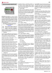
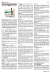
EDS
EDS ENERGY EFFICIENCY MANAGER
the user can use to know the physical address of the device.
To go the next setup screen, press the Scroll down key.
2.2.2.- DHCP assignment
After entering the setup menu, the device displays DHCP
(Dynamic Host Configuration Protocol), and shows the by
default NO option. To modify the option displayed on the
screen, press Scroll RIGHT until the YES option appears. Do this
twice and the device cyclically displays both options until one
of them is validated.
When the DHCP server is activated via the YES caption, press
the Scroll down key to go to the next option.
2.2.2.1.- Client ID - ( DHCP YES )
EDS (Efficiency Data Server) is an energy efficiency
manager. The device has an RS-485 communications bus, as
well as 8 digital inputs and 6 digital outputs via relay, which
allow it to communicate with external field devices,
representing and storing the information via its Ethernet
connection and integrated web server. EDS also has a
standard XML server, through which other external
applications can integrate information from the device easily
and intuitively.
This document represents the user and operation manual of the
EDS device. If misplaced, the manual may be downloaded from
CIRCUTOR's web site:
www.circutor.com
Disconnect the device from the power supply
source before undertaking any form of
maintenance, modification of connections,
repairs, etc. If you suspect any operational
faults in the device or in its protection system, remove the
device from service. The design of the device makes it
easy to replace in the event of a fault.
1.-
Buttons
The front panel of the EDS device has an alphanumeric LCD
display, along with four function buttons, allowing the user to
navigate through the setup screens of the device.
The buttons have two operating methods:
SHORT KEYSTROKE: when the user presses the function button for
less than two seconds.
LONG KEYSTROKE: when the user presses the function button for
more than two seconds.
The buttons have the following functions:
Scroll left: edit button, scroll the cursor to the left to modify
the numerical or alphanumeric digit.
Scroll RIGHT: edit button, scroll the cursor to the right to modify
the numerical or alphanumeric digit.
Scroll up: the function of this button is to modify the digit
where the edit cursor is located. If there is no cursor on the
screen, move up to the next step of the previous setup option.
Scroll down: the function of this button is to modify the digit
where the edit cursor is located. If there is no cursor on the
screen, move down to the next step of the previous setup
option.
2.-
Setup
The device has two clear setup routes: the first one is related
to the Ethernet integration start-up (IP addressing), and the
second one is related to the setup of the internal application
and possible association with other field devices via the
RS485 bus.
2.1.- Network addressing
EDS is a device with self-detecting Ethernet 10/100BaseTX
connectivity. This means that, in order to integrate the device
into a Local Area Network, it must be provided with a previous
IP addressing configuration.
The user can access the setup parameters via the display and
the function keys on the front panel of the device, or through
the internal setup web site, which is accessible via a
conventional Internet browser.
2.2.- Network parameter setup (Keyboard)
The configuration of the Ethernet network parameters can be
integrally carried out using the function buttons on the front
panel of the device.
To access the setup menu, simultaneously hold down the
keys Scroll RIGHT, Scroll up and Scroll down for more than two
seconds. The device shows the text hold on 2 seconds to enter
setup on screen and after 2 seconds the display shows
ENTERING SETUP RELEASE THE KEYS.
2.2.1.- MAC address
After entering the setup menu, the device displays MAC
(Media Access Control) physical address on screen, with a
00:26:45:XX:XX:XX type format. This is an information panel that
After activation of the DHCP authentication and the
subsequent validation, the device displays the Client ID
parameter setup on the screen, which makes reference to the
DHCP name of the device to be logged into the Ethernet
network.
The edit cursor in the first digit is activated via the Scroll RIGHT
key. This key and the Scroll up and down buttons can be used
to parameterise an alphanumeric data entry of up to 20 digits.
After the data is entered, press the Scroll RIGHT key twice until
the edit key disappears, and then validate the data with the
Scroll down key, by going to the next screen.
2.2.5.3.- Act. Mode Port - ( active mode yes )
The “Act. Mode port” option is the access port of the central
server, where the AMB connections software has been
installed. This computer must have an access port for
connecting all remote devices, in order to establish a
transparent communications tunnel.
In this case, access to the Internet connection from the central
location will require the use of a connection router, which will
establish a NAT access rule to activate a TCP connection port
in the connection server (connection path).
An access port must be activated in the Internet access
router, which will internally transfer the public communication
frames to the AMB internal connection server and to a port
specified by and known to the user.
The port activated in the communication router must be
configured in the "Port" section.
2.2.5.4.- Act. Mode Identifier - ( active mode yes )
Each element connected to the AMB system must have an
identifier or alias (“Act. Mode Id.”). This identifier is
alphanumeric and the user must record it in order to enable
the server connection.
An "Identifier" cannot be duplicated within the same
connection server.
2.2.2.2.- Assigned values - ( DHCP YES )
2.2.6.- Enable Security
After entering the Client ID name in the device for the first time,
the device displays the parameters assigned by the DHCP
server on the screen. Given that the parameters that are being
edited will not be fixed until the device is configured, it
displays the following fields on the screen, which cannot be
edited (asterisk in upper left hand corner):
A user and edition password can be activated in the device,
thus avoiding modification of the configuration parameters.
The device displays NO by default. It should be pointed out that
if the password is activated, it will be present in all the
device's setup and display accesses (keyboard, Web setup
and internal applications).
-
2.2.8.1.- IP
-
2.2.8.2.- Netmask
-
2.2.8.3.- Gateway
-
2.2.8.4.- Primary DNP
-
2.2.8.5.- Secondary DNS
Given that the DHCP server has not yet been assigned the
Ethernet addressing values (displaying 000.000.000.000), press
the Scroll down key twice to go the Primary NTP option.
2.2.3.- Primary NTP
The device can be synchronised with a time and date NTP
server (Network Time Protocol) server in the UTC time
system. The device does not display a value by default,
indicating that the synchronisation is completed via DHCP, if
the network server allows this to be done. In this case, it is the
main server.
To configure an NTP server that is different from the DHCP
(0.0.0.0), press the Scroll RIGHT key, enabling the edit cursor in
the first digit. Set parameters for an alphanumeric data entry
with the Scroll up and down buttons up to a maximum of 20
digits, indicating an http address or internal or external IP (if
the device has Internet access). After establishing the
parameters, press the Scroll RIGHT key twice until the edit key
disappears, and then validate the data with the Scroll down
key, by going to the next screen.
Servers available on the Internet:
-
es.pool.ntp.org
-
pool.ntp.org
2.2.3.1.- Secondary NTP
configuration of the secondary NTP server, carry out the same
procedure as with the Primary NTP.
2.2.4.- Time Zone
To configure the time zone, press the Scroll RIGHT key to
select the time zone where the EDS device is located.
After selecting the zone, press the Scroll down key, and go to
the next screen.
2.2.5.- AMB® - Active Mode Bridge
The AMB system reverses the connection process of remote
devices. In this case, it is the equipment that starts the
communication process with the connections server located in
a central computer, by creating a transparent communications
tunnel between the equipment and connection server.
Therefore, the user avoids having to set up and maintain a
fixed IP system or DynDNS in its remote control locations.
2.2.5.1.- Active mode
To configure an access route, press the Scroll RIGHT key, until
the YES option appears. When the Active mode is activated via
the YES caption, press the Scroll down key to go to the next
option.
2.2.5.2.- Act. Mode Host - ( active mode yes )
The “Act. Mode Host” option determines the IP destination
where the device is actively connected. This is an
alphanumerical field that can be configured with an IP address
or Web routing functions.
To modify the option displayed on screen, Scroll RIGHT until
the option YES appears. Do this twice and the device cyclically
displays both options until one of them is validated. Establish
the parameters for the alphanumeric data entry with the Scroll
up and down buttons, up to 20 digits corresponding to the user,
and when the data is validated, repeat the operation with the
password. Validate the data (Scroll right and scroll down).
2.2.7.- Confirm Changes - ( DHCP YES )
The information must be validated to save the setup. The
device displays yes by default. When the completed
configuration is validated, press the scroll down key and the
device saves the data and leaves configuration.
If the setup is not saved, Scroll RIGHT until the no option
appears. Do this twice and the device cyclically displays both
options until one of them is validated with the scroll down key
2.2.8.- Client ID - ( DHCP NO )*
If the DHCP server is not activated, shown in section 2.2.2.DHCP assignment, validate the NO option using the Scroll
down key and go to the next screen.
2.2.8.1.- IP - ( DHCP no )*
The user configures an IP address for the EDS device using
the configuration option. To do this, press the Scroll RIGHT key
to activate the edition cursor in the first digit. Press the Scroll
up and down buttons to establish the parameters of a
000.000.000.000 type numeric data entry. After establishing the
parameters, press the Scroll RIGHT key twice until the edition
key disappears, and then validate the data with the Scroll
down key, by going to the next screen.
2.2.8.2.- NetMask - ( DHCP no )*
To configure the (NetMask) setup, press the Scroll RIGHT key,
activating the edition cursor in the first digit. Press the Scroll
up and down buttons to establish the parameters of a
000.000.000.000 type numeric data entry. After establishing the
parameters, press the Scroll RIGHT key twice until the edition
key disappears, and then validate the data with the Scroll
down key, by going to the next screen.
2.2.8.3.- Gateway - ( DHCP no )*
To configure the Gateway setup, press the Scroll RIGHT key,
activating the edit cursor in the first digit. Press the Scroll up
and down buttons to parameterise a 000.000.000.000 type
numeric data entry. After establishing the parameters, press
the Scroll RIGHT key twice until the edition key disappears, and
then validate the data with the Scroll down key, by going to the
next screen.
2.2.8.4.- Primary DNS - ( DHCP no )*
To configure the Primary DNS configuration, press the Scroll
RIGHT key, activating the edition cursor in the first digit. Press
the Scroll up and down buttons to establish the parameters of
a 000.000.000.000 type numeric data entry. After establishing
the parameters, press the Scroll RIGHT key twice until the
edition key disappears, and then validate the data with the
Scroll down key, by going to the next screen.
M98237501-03-12A
EDS
2.2.8.5.- Secondary DNS - ( DHCP no )*
3.-
To configure the secondary DNS server, carry out the same
procedure as with the Primary DNS.
EDS is an energy efficiency manager with a Web server
display, from which the user can see the status of the device
inputs and outputs in real time, as well as any possible action
to be taken.
2.2.8.6.- Other setups - ( DHCP no )*
After configuring the secondary DNS, the other setup screens
correspond to the same ones as in the activated DHCP mode;
consequently the setup procedure will be the same as the one
for sections:
-
2.2.3.- Primary NTP
-
2.2.3.1.- Secondary NTP
-
2.2.4.- Time Zone
-
2.2.5.- AMB® - Active Mode Bridge
-
2.2.6.- Enable Security
-
2.2.7.- Confirm Changes - ( DHCP YES )
2.2.8.7.- Manual Date and Time setup
If there is no authentication configuration by the DHCP
system, and if there is no Primary and Secondary NTP server
available, EDS allows the time and date to be configured
manually when validating the changes by displaying the
caption adjust clock. The date and time are displayed on
screen with the following format: YYYY-MM-DD HH:MM. To
configure them, press the Scroll RIGHT key, activating the
edition cursor in the first digit. Use the Scroll up and Scroll
down buttons to establish the parameters of the numerical data
entry. After establishing the parameters, press the Scroll RIGHT
key twice until the edition key disappears, and then validate
the data with the Scroll down key, leaving setup and validating
the configuration.
As well as serving the data stored internally via the Web, the
device has an XML server, enabling the user to send GET and
PUT type requests.
3.1.- Web Server
In the Address field, enter the IP address being configured;
do the same with the (Netmask) and the (Gateway) port if
necessary. After entering the device setup, press “Setup” to
send the setup to the equipment.
2.3.2.- DHCP IP assignment
To assign the DHCP name, activate the option using the
upper right hand arrow and select On. Once the setup fields
have been enabled, enter the MAC address.
In the Address field, enter an unused, temporary IP address,
which is within the working range of your computer. In the
Host Name field, enter the DHCP name to be assigned to the
equipment. Optionally, the user can configure the parameters
of the ClientID field. The default VendorID of the device is
CIRCUTOR.
2.2.9.1.- Ping system
2.3.3.- Setup web site
Once connection to the Local Area Network (LAN) is
established and the IP address or DHCP name is configured,
the device has an internal web site where the user can
integrally modify all the parameters concerning network
configuration (2.2.10.- Internal setup web site), and even the
time and date data.
Where name_dhcp is the name assigned and authenticated
by the name server of the local area network (LAN).
3.2.- XML server
The XML server is an excellent integration tool for external
applications. EDS has a server available whose access
requests are identified in this manual (see XXX).
The electronic meters have an impulse output that is
proportional to the recorded power. With its inputs, EDS is a
centralising unit with 8 digital inputs (opto-coupled) for reading
impulses from electricity, water, gas, etc. meters. The value of
these impulses is associated to 8 memory records, stored in a
non-volatile memory.
Each registry is 32 bits (4 bytes), so it counts a maximum of
up to 4,294,967,295 impulses. When a memory record
reaches this value, the meter is reset back to zero.
3.3.2.- Input logical status function (0/1)
The 8 digital inputs in the device are voltage-free and have an
input logical status detection function. This means that when a
bridge is set up between the common and one of the digital
inputs, the device detects that the input has closed, and
displays the status via both communications servers.
3.4.- Digital outputs
The device has 4 relay digital outputs. The user can use
remote control to carry out actions on the outputs (open,
close, create an impulse).
When the data is validated, the screen displays the DOING PING
caption and will then show the results:
PING RESULT: time out - no response was obtained from
the host
http://dhcp_name
Where xxx.xxx.xxx.xxx is the IP address assigned by the user.
Its Web server and internal memory enable the user to extract
graphics and tables of impulses received during a certain
period (table and graphic function).
The device displays the physical address within the setup
menu, as shown in section 2.2.1.- MAC address. Press the
SCROLL RIGHT key to go to the on-screen caption HOST PING. To
enter the name or IP address to carry out the ping test, press
the Scroll RIGHT key to activate the edit cursor in the first digit.
Press this key and the Scroll up and down buttons to establish
the parameters of an alphanumeric data entry of up to 20
digits. After the data is entered, press the Scroll RIGHT key
twice until the edit key disappears, and then validate the data
with the Scroll down key, by going to the next screen.
PING RESULT: OK - a response was obtained from the host
http://xxx.xxx.xxx.xxx
-
The minimum duration of the impulse or status change of the
digital input must be 50 ms. The minimum time between two
successive impulses must also have a minimum duration of
50 ms. This represents a maximum sampling frequency of 10
Hz.
To do this, EDS has a PING section, from which the user can
carry out an IP connectivity test with an IP address or name,
emulating the ping command of a conventional operating
system.
-
-
3.3.1.- Impulse meter function
To confirm IP connectivity via a Local Area Network (LAN) or
the Internet using a DSL or 3G router, the user sometimes has
to know if the EDS device has this IP access or if the unit has
particular access to a certain host.
-
To see the Web display interface, the user must access it via
the http address below:
The device has a total of 8 digital inputs, whose function is to
count energy impulses coming from external sensors, or for
detection of the logical status of the input. The contacts
associated to the digital inputs of the device must be voltagefree dry contacts.
2.2.9.- Display of setup parameters
If a user and password are available even when the user does
not have one, all the setup parameters can be visualised
without being able to change them (asterisk in top left hand
corner).
Once the Ethernet addressing is configured and integrated
into the Ethernet network, the device variables are visible to
the user via a conventional Internet Explorer browser (with
Java
plug-in
installed
on
the
computer
http://www.java.com/es/download/). Another access interface
is the PowerStudio Scada Client.
3.3.- Digital inputs
When the setup is validated, the DONE caption appears,
returning to the main screen.
To display the setup parameters, the user must enter the
setup menu by simultaneously pressing the SCROLL RIGHT ,
SCROLL UP and Scroll down keys. The user must Press the Scroll
down key twice for complete visualisation of the device
configuration.
Operation
These actions can be manual, or via programming in the
events section of the device (see PowerStudio Scada
manual).
3.5.- RS-485 expansion bus
When a result is obtained by the device, press the Scroll down
key and the device goes back to the by default display
screens.
2.2.10.- Internal setup web site
The device has an RS-485 communications bus that allows it
to communicate with external peripherals, act as a
communications master and store data recorded in its 200Mb
cyclic memory.
After establishing the parameters with the keyboard and
connecting to the Ethernet, the device has a setup web site
where the user can integrally modify the data entered with the
keyboard. The setup web site is at the http address below:
Its Web accessibility and memory enable the user to view
data coming from devices connected to the bus in real time,
and easily and simply view graphics and tables of the
parameters registered by the device.
-
http://xxx.xxx.xxx.xxx/html/setup.html
-
http://dhcp_name/html/setup.html
Where xxx.xxx.xxx.xxx is the IP address assigned by the user.
Where name_dhcp is the name assigned and authenticated
by the name server of the local area network (LAN).
2.3.- Network parameters setup (Software)
Configuration of addressing can be done in the same way as
using the keyboard via the IPSetup.exe file, available on a
CD supplied with the device.
2.3.4.- Access via password
If an access user name and password have been
parameterised, the device requests these access parameters
when trying to access via the web site in the following pop up
screen:
As well as linking communications with devices connected to
its RS-485 communications bus, the device also has the
capacity to make connections via IP connectivity (local or
remote), either through an IP via addressing or DHCP name.
To add devices to the EDS energy device setup, the user
must install the PowerStudio or PowerStudio Scada
application, so as to export a new setup of the device, adding
new analyzers or slaves connected to the unit.
EDS allows configuration of up to 5 slave devices connected
to its network.
2.3.1.- Fixed IP assignment
3.6.- Additional PS/PSS features
To assign a fixed IP address, enter the MAC address
displayed on the device screen as shown in section 2.2.1.MAC address address, the format of which is 00:26:45:XX:XX:XX.
To configure the other system features, read the PowerStudio
/ Scada Editor manual. It has all the information the user
needs about:
M98237501-03-12A
EDS
-
Importing or exporting the setup of the EDS system
-
Setup of new devices or slaves
-
Tariff discriminators / calendars
-
Calculated variables
-
System events and alarms
-
Authentication setup
-
Web system security
-
Etc.
Without the PowerStudio Editor tool, the measurement
application cannot be configured to provide new features for
the EDS device. Consequently, the user must install the
software, thus making it possible to integrally configure the
display server and vary the settings of the display, connected
devices, alarms, etc.
4.-
-
devices: field identifying the XML as a response to the
device list request
-
id: name of each one of the devices
4.3.2.- Information about the device
4.3.4.2.- Instantaneous value of all variables
Request for detailed information about the devices. Each of
devices you want more information, should be include in the
XML sentence ?id=device1?id=device2?
Request for instantaneous values of all the variables of the
device (if information is needed about more devices, link the
other requests below with id=device?):
http://x.x.x.x/services/user/values.xml?id=device?
http://x.x.x.x/services/user/deviceInfo.xml?id=device?
http://dhcp_name/services/user/deviceInfo.xml?id=device
?
XML instructions
name.variable
This way the software knows which variable it is and what
device must be asked to find out the value of the variable.
When an incremental variable is discriminated (energy,
impulse meter or similar), the information about the
parameterised discriminator is added to the basic code:
-
name_discriminator@type_time:variable
The discriminable variables are shown in the list with an
asterisk.
4.2.- EDS variables list
If slave devices are provided, the frames sent to EDS are
identified in the same way by name and variable, as shown in
section 4.1.-.
The following table shows the definition of the variables
available in EDS.
Digital inputs
Digital Input 1
Digital input 2
Digital input 3
Digital input 4
Digital input 5
Digital input 6
Digital input 7
Digital input 8
Digital Output Status
Digital Output 1
Digital Output 2
Digital Output 3
Digital Output 4
Digital Output 5
Digital Output 6
Forced Outputs Impulse
Digital Output 1
Digital Output 2
Digital Output 3
Digital Output 3
Digital Output 5
Digital Output 6
Date and time
Date and Time
Device status
Device status
XML - Status Value
DI1
DI2
DI3
DI4
DI5
DI6
DI7
DI8
XML - Force Output
DO1
DO2
DO3
DO4
DO5
DO6
XML - Impulse
DOP1
DOP2
DOP3
DOP4
DOP5
DOP6
XML - Value
VDTTM
XML - Impulse
STATUS.
XML - Meter Value
C1
C2
C3
C4
C5
C6
C7
C8
Forced Open / Close
0/1
0/1
0/1
0/1
0/1
0/1
Forced Impulse
≠0
≠0
≠0
≠0
≠0
≠0
Values
Last Server communication
Values
1
Communication OK
4
Not initialized
18
Port incorrect
34
Comm Errors
66
Device incorrect
<var> ... </var>
...
</device>
...
<devices>
-
description: description of device
-
type: device type
-
typeDescription: detailed description of the device
-
var: name of each of the variables of the device; expressed
as name.variable
4.3.3.- Information about the variable
The user can request detailed information about one or more
variables from a device and even make one single request for
the information about all the variables available in the device.
4.3.3.1.- Information about one or more variables
Request for detailed information about one or more variables
of the device (if information is needed about more variables,
link the other requests below with var=device.variable?):
http://x.x.x.x/services/user/varInfo.xml?var=device.variable?
http://name_dhcp/services/user/varInfo.xml?var=device.variab
le?
4.3.3.2.- Information about all the variables
Request for detailed information about all the variables of the
device (if information is needed about more devices, link the
other requests below with id=device?):
http://x.x.x.x/services/user/varInfo.xml?id=device?
http://dhcp_name/services/user/varInfo.xml?id=device?
<varInfo>
<var>
<id> … </id>
<title> ... </title>
<hasValue> T </ hasValue>
<hasLogger> T </ hasLogger>
<sampleMode>… </ sampleMode>
<measureUnits>… </ measureUnits>
<unitsFactor>… </ unitsFactor>
<decimals>… </ decimals>
</ var>
…
<varInfo>
-
title: brief description of the variable
-
hasValue: indicates if it is possible to request the
instantaneous value of the variable (True / False)
4.3.- XML Services
-
The requests must follow the URI standard (RFC 2396), so
the user of these requests should take this detail into account
when making such calls (especially in cases where the name
of any device contains non-ASCII characters). Take into
account that the length of the request must not under any
circumstance exceed 4000 characters.
hasLogger: indicates if it is possible to request the log of
the variable (True / False)
-
sampleMode: type of variable and mode used to group
values
-
measureUnits: variable unit
-
unitsFactor: power of 10 indicating the multiplying factor in
the log file
-
decimals: decimals of the variable
<devices>
<id> ... </id>
<devices>
<value> ... </value>
</ variable>
...
<type> ... </type>
<typeDescription> ... </typeDescription>
id: variable name in device.variable format
With this request the XML service returns the list of connected
devices to the EDS energy efficiency manager.
http://x.x.x.x/services/user/devices.xml
http://name_dhcp/services/user/devices.xml
<id> … </id>
<description> ... </description>
-
4.3.1.- Configured devices request
<values>
<variable>
<id> ... <id>
4.1.- Type of variables
-
http://dhcp_name/services/user/values.xml?id=device?
<devices>
<device>
Not only does EDS function as an excellent energy efficiency
manager for local and multi-point networks, it also has a
default XML requests server that enables it to be easily and
intuitively integrated into a SCADA or remote monitoring
system. The device, via its IP address, attends to GET and
PUT requests that can carry out different functions on the
device.
The device has a list of available variables, in accordance
with the device features. The basic code is made up of the
device name and the variables separated by a dot:
http://dhcp_name/services/user/values.xml?var=device.variab
le?
4.3.4.- Instantaneous variable value
The user can request the instantaneous values of one or more
variables, and can even request the information about all the
instantaneous data with just one request.
4.3.4.1.- Instantaneous value of one or more variables
Request for the instantaneous value one or more variables of
the device (if information is needed about more variables, link
the other requests below with var=device.variable?):
http://x.x.x.x/services/user/values.xml?var=device.variable?
</values>
-
id: identifier of the variable
-
value: value of variable at the time of the request
4.3.5.- Historical data
Request for historical data registry of an incremental variable.
Returns information on one or more variables between the
“begin” and “end” dates. Each variable for which information is
required must be included in the request as
?var=device.variable
When only the date is required, the format is DDMMYYYY;
When the date and time are required, the format is
DDMMYYYYHHMMSS. Both the date and the time must be
expressed in UTC (Universal Coordinated Time).
The grouping period can be defined by different criteria:
-
value in seconds (for example 900): value in seconds in
which the data is grouped
-
ALL the data is grouped into a single value
-
AUTO: grouping is automatic with predefined intervals
according to “begin” and “end”
-
FILE: data not grouped. returns the information as
registered in the database
-
if the period parameter does not appear in the request, it is
considered as value 0 and the data is not grouped
http://x.x.x.x/services/user/records.xml?begin=010320110000
00?end=31032011000000?var=device.variable?period=900
http://dhcp_name/services/user/records.xml?begin=01032011
000000?end=31032011000000?var=device.variable?period=
900
<recordGroup>
<period>… </ period>
<record>
<dateTime> ... </ dateTime >
<field>
<id> … </id>
<value>… </value>
</field>
</record>
…
</recordGroup>
-
recordGroup: field identifying the XML as a response to
the variable register request
-
period: recording period; time between recordings
-
record: identifies each recording (dateTime: date and time
of the sample
-
field: standard recording value (for others consult PS
manual)
-
value: value of variable at the time of the request.
4.3.6.- Historical events file
As this user manual describes, the PowerStudio / Scada
Editor makes it possible to configure events or alarms within
the EDS device and record them in the internal memory.
With the following request, the user can request the historical
events file between the dates defined. Every event that is
requested with a historical events file is defined as
?id=name_event
When only the date is required, the format is DDMMYYYY;
when the date and time are required, the format is
DDMMYYYYHHMMSS. Both the date and the time must be
expressed in Universal Coordinated Time.
http://x.x.x.x/services/user/records.xml?begin=010320110000
00?end=31032011000000?id=event_name
M98237501-03-12A
EDS
http://dhcp_name/services/user/records.xml?begin=01032011
000000?end=31032011000000? id=event_name
<main>
<recordGroup>
<id> … </id>
<record>
<date>… </ date>
<eventId> … </eventId>
<annotation> … </annotation>
<value>… </ value>
</record>
...
</recordGroup>
…
<main>
4.3.8.1.- Test commands
Before initiating implementation of the active events system,
there are a number of PUT type test requests between the
listener and the producer (remote engine) and vice versa, the
aim of which is to test and ensure connectivity between both
systems.
http://ip_producer:port/services/user/testListener.xml
<listener>
<ip>ip_listener</ip>
<port>80</port>
</listener>
-
ip_listener defines the listener's IP, to which the producer
sends the response request
-
port: defines the listener's port, to which the producer
sends the response request
main: field identifying the XML as a request
-
recordGroup: field that groups all the recordings of an event
-
id: event identifier
-
record: identifies each record
-
date: event date and time
http://ip_listener:port/services/user/testProducer.xml
-
eventId: event identifier
request to which the listener must reply with "received" (200).
-
annotation: event annotation
-
value: event value
OFF: inactive event
ACK: event acknowledged
4.3.7.- Device events
Returns the information about recorded events of one or more
devices between the dates “begin” y “end”. Each device for
which information is required must be included as ?id=device
http://x.x.x.x/services/user/records.xml?begin=010320110000
00?end=31032011000000?id=event_name?
http://dhcp_name/services/user/records.xml?begin=01032011
000000?end=31032011000000?id=event_name?
When only the date is required, the format is DDMMYYYY;
when the date and time are required, the format is
DDMMYYYYHHMMSS. Both the date and the time must be
expressed in Universal Coordinated Time.
<main>
<recordGroup>
<device> ... </device>
<record>
<dateTime> … </dateTime>
<field>
<id> … </id>
<value>… </ value>
</field>
…
</record>
...
</recordGroup>
…
</main>
-
main: field identifying the XML as a request
-
recordGroup: field that groups all the recordings of an event.
-
device: device the records make reference to
-
record: identifies each recording
-
dateTime: event date and time
-
field: identifies each field
-
id: Identifier
-
value: event value
4.3.8.- Active Events
EDS has an XML active events service whose aim is to
enable an external agent or integration system to be
registered as a listener and record the events or alarms that
occur in the device.
The device keeps a distribution list of active users, to which it
sends events that take place locally via the creation of
incidents.
<all>F</all>
</listener>
-
The listener can send the request with the following message
body to check connectivity with the remote search engine
(producer):
-
ON: active event
<listener>
<ip>ip_listener</ip>
<port>80</port>
When the producer (remote search engine) receives the test
request from the listener, it returns the following request:
4.3.8.2.- Registration of a listener
Any agent or listener who wants to register in a remote search
engine, or producer who wants to receive the incidents
recorded by the search engine in real time, must carry out the
following PUT request to the producer with this format:
http://ip_producer:port/services/user/listener.xml
This request must contain the following body in the message,
in which the listener and the type of data to be received are
defined:
<listener>
<ip>ip_listener</ip>
<port>80</port>
<all>T</all>
<listener>
-
ip_listener the listener's IP is defined, to which the
producer sends the events that are created
-
port: defines the listener's port, to which the producer
sends the events that are created
The all section defines the type of information that is to be
accessed (True / False).
-
True:) indicates to the producer that all the active events
list available must be sent
-
False:) indicates to the producer that only the events that
took place since the last request must be sent
4.3.8.5.- Reception of events
When there is any change in the events, the request that the
producer creates against the listeners' distribution list giving
information about the events is PUT type with the following
Syntax:
http://ip_oyente:port/services/user/producer.xml
The request contains the following information in XML format
in the body of the message: information about the events
produced:
<producer>
<all>T/F</all>
<event>
<id>driverId.driverId.driverId…eventId</id>
<name>Event 1</name>
<description>Description 1</description>
<annotation>Annotation 1</annotation>
<dateTime>25112010201034</dateTime>
<whyFired>ACTIVATION</whyFired>
</event>
<event>
<id>driverId.driverId.driverId…eventId</id>
<name>Event 2</name>
<description>Description 2</description>
<annotation>Annotation 2</annotation>
<dateTime>25112010201034</dateTime>
<disabledDateTime>25112010201103</
disabledDateTime >
<whyFired>DEACTIVATION</whyFired>
</event>
…
</producer>
-
all: all the events (True) or changes(False)
-
event-id: producer and identifier of the event
-
whyFired: ACTIVATION, DEACTIVATION
Notes referring to the active events:
-
4.3.8.3.- Deletion or loss of the listeners' list
The producer can completely or partially lose or eliminate the
listeners' list for different reasons:
-
The listener does not answer: when new events or
changes in these events take place, the producer
instantaneously informs all listeners on the list. When the
producer is faced with a communication problem with a
listener, a total of fifty retries are made to send information.
If the listener does not respond to these requests, the
producer deregisters the listener from the distribution list.
-
The producer has rebooted or has temporarily stopped
operating: if the producer receives an update or generates
a reset for any reason, (firmware, update, loss of power
supply, etc), the entire listeners' list is lost and from then on
stops sending events to the previously associated listeners.
4.3.8.4.- Maintenance of the listeners' list (alive)
Given that there are several reasons why the listeners' list
might be totally or partially affected, the external integration
system needs to implement an (alive) test system against the
producer to ensure that the IP is kept active for a long period
in the distribution list.
It is recommended that the test system is automatic and with
a periodicity of no more than 10 minutes between each test
frame dispatch. The (alive) test system is based on the
updating of the listener IP, again against the producer,
although only the event changes are requested (False):
If the external integration application has remained inactive
for a long period of time, a request to the producer asking
for the entire list of active events is recommended using a
True request. This way the listener again has all the
information lost during the period of inactivity.
Note: if the producer has implemented http authentication
by user and password, it must be implemented in the
listener by the user.
4.3.9.- Forcing of variables
This request is used to send the variable forcing order (or
writing) to the system. The request should include the name of
the device that wants to make the request. It is important to
incorporate the authentication data when this is necessary.
<forceVariables>
<forceVar>
<forceName> ... </forceName>
<forceValue> ... </forceValue>
</record>
</ forceVar>
...
</forceVariables>
-
forceVariables: field identifying the XML as a request
-
forceVar: Information from each variable to be forced
-
forceName: variable name in device.variable format
-
field: identifies each field
http://ip_producer:port/services/user/listener.xml
This request must contain the following body in the message,
in which the listener and the type of data to be received are
again defined:
M98237501-03-12A
EDS
5.-
Technical specifications
Power circuit:
- Single-phase (phase – neutral) A1 – A2 :
- Frequency:
- Maximum consumption:
- Working temperature:
- Water content (non-condensing):
Mechanical features:
- Case material:
- Equipment protection degree:
- Dimensions (mm):
- Weight:
- Maximum operating height:
Inputs features:
- Type:
- Maximum activation current:
- Insulation:
Network interface:
- Type:
- Connector:
- Network protocols:
Serial interface:
- Type:
- Transmission speed (configurable):
- Data bits:
- Parity:
- Stop bit
6.-
Standard version
85…264 V ac / 120…300 V dc
47…63 Hz
5…8 VA
-10 …+ 60 ºC
5 … 95 %
UL94 - V0 self-extinguishing plastic
IP 20
105 x 70 x 90 mm (6 modules)
250 g
2,000 m
Voltage-free opto-insulated (dry contact)
50 mA
1500 V
Ethernet 10BaseT / 100BaseTX self-detectable
RJ45
HTTP / Modbus/RTU in RS-485 bus
Three-wire RS-485 (A/B/S)
4800, 9600, 19,200, 34,800, 57,600, 115,200 bps
8
No parity, odd, even
1/2
Relay
750 VA
250 V ac
5 A with resistive load
3 x 10⁴ operations
2 x 10⁷ operations
LED symbols:
- Power :
- Slaves:
- Left RJ45 led:
- Right RJ45 led:
Equipment power supply and CPU activity
Communicating slave devices shutdown
Green: Full duplex / Yellow: Half duplex / Activity
Green: 100 Mb/s / Yellow: 10 Mb/s / Link
Display:
- Type:
- Characters:
- Back lighting:
2 lines, alphanumeric
20
Yes
Safety:
Installation category Class III / EN61010 double-insulated electric shock protection class II.
Connect the device to a power circuit protected with gl fuses in compliance with IEC 269, or
M fuses, with values from 0.5 to 1A. It must be fitted with a circuit breaker switch or
equivalent device, in order to be able to disconnect the device from the power supply. The
power supply cable must have a cross-section of at least 1 mm2.
Standards:
EC, IEC 60664, VDE 0110, UL 94, EN61010-1, EN55011, EN 61000-4-2, EN 61000-4-3,
61000-4-11, EN 61000-6-4, EN 61000-6-2, EN 61000-6-1, EN 61000-6-3, EN 61000-4-5
Connections
DETAILS OF THE POWER SUPPLY AND RS-485 COMMUNICATION (SLAVE EQUIPMENT)
CONNECTIONS
7.-
Output Features:
- Type:
- Maximum switching power:
- Maximum switching voltage:
- Maximum switching intensity:
- Electrical life (250 Vac / 5 A):
- Mechanical working life:
DETAILS OF DIGITAL INPUT 4 ACTIVATION
Technical Service
If you have any doubts about the operation of the unit or suspect any malfunction, contact our service staff at CIRCUTOR, SA
CIRCUTOR, SA - Technical Assistance Service
Vial Sant Jordi, s/n
08232 – Viladecavalls (Barcelona), SPAIN
Tel.: 902 449 459 (Spain)
Tel.: +34 937 452 900 (outside Spain)
e-mail: [email protected]
M98237501-03-12A