1
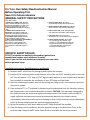
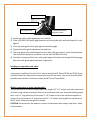
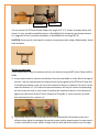
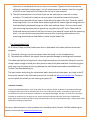
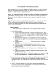
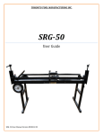
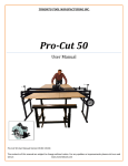
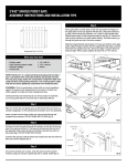
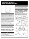
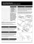
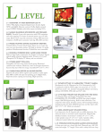
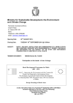
TORONTO TOOL MANUFACTURING INC.
BT‐24, BT‐36, BT‐50 User Manual The contents of this manual are subject to change without notice. For any updates or improvements please visit our web site at: www.torontotool.com BT‐50, BT‐36, BT‐24 Bench Top Clamp and Saw Guide USER GUIDE: Thank you for purchasing the BT series Clamp and Saw Guide. Below you will find the installation instructions to mount the BT series to your workbench. For portability, the BT series can also be mounted to a portable worktable. As an alternative, you can also construct a saw horse to mount your BT clamp and saw guide to as shown below. The BT Series Clamp Guide can be installed in a variety of ways: 1) To either the left or right ends of your workbench as shown. 2) To the front or back of your workbench. 3) For portability, the BT series Clamp Guides can be mounted to a portable worktable such as the contractor table offered by Toronto Tool. 4) The BT series Clamp and Saw Guides can also be mounted to 2” X 6” lumber and clamped in a portable table such as a WorkMate or can be mounted to a saw horse. Please refer to the “How To” section of our web site to see how to construct a mounting assembly for the BT Clamp and Saw Guide. www.torontotool.com For Your Own Safety Read Instruction Manual
Before Operating Tool
Save it for future reference
GENERAL SAFETY PRECAUTIONS
(For All Tools)
1. KNOW YOUR POWER TOOL. Read the
owner’s manual carefully. Learn the tool’s
applications and limitations, as well as the
specific potential hazards peculiar to it.
2. KEEP GUARDS IN PLACE and in working
order.
3. REMOVE ADJUSTING KEYS AND
WRENCHES. Form habit of checking to
see that keys and adjusting wrenches are
removed from tool before turning it on.
4. KEEP WORK AREA CLEAN. Cluttered
areas and benches invite accidents.
5. DON’T USE IN DANGEROUS ENVIRONMENT.
Don’t use power tools in damp or
wet locations, or expose them to rain.
Keep work area well lighted. Don’t use
tool in presence of flammable liquids or
gases.
6. KEEP CHILDREN AWAY. All visitors
should be kept safe distance from work area.
7. MAKE WORKSHOP KID PROOF with padlocks,
master switches, or by removing starter keys.
8. DON’T FORCE TOOL. It will do the job better
and safer at the rate for which it was designed.
9. USE RIGHT TOOL. Don’t force tool or
attachment to do a job for which it was not designed.
10. WEAR PROPER APPAREL. Do not wear
loose clothing, gloves, neckties, rings,
bracelets, or other jewellery which may get
caught in moving parts. Nonslip footwear
is recommended. Wear protective hair
covering to contain long hair.
SPECIFIC SAFETY RULES
DO NOT let comfort or familiarity with product (gained from
repeated use) replace strict adherence to safety
rules. If you use this tool unsafely or incorrectly, you can suffer
serious personal injury.
Installation Instructions: (Installing to your workbench) 1) Remove the BT series from the packaging and inspect the contents. 2) Find the 5/16” mounting holes on the bottom rail and the one 5/16” mounting hole on the side rail. You will require 1‐1/2” long by 5/16” lag bolts with washers or nuts and bolts with washers (not included) to complete the installation of your BT Clamp and Saw Guide. 3) Open the clamp approximately one inch by turning the clamp screws in the counter‐clock wise direction as shown. 4) Place a sheet of ½” or ¾” plywood in the opening of the clamp and close the clamp by rotating the clamp screws in the clockwise direction as shown. CAUTION: The top clamp is designed to flex under pressure but do not over‐tighten the clamp screws. The clamps screws are able to supply sufficient and excessive pressure to permanently warp the top clamp in certain circumstances when the product you are clamping is thick enough to allow excessive downward travel of the top clamp beyond the required clamping pressure. 5) Select the location on your bench where your BT Clamp Guide will be installed. 6) Place the clamp on the workbench with the plywood resting on the bench top. Check to be sure the lower clamp of the BT series Clamp Guide is level with the bench top surface. 7) Locate and mark the 5/16” mounting holes on your workbench of the bottom rail and the side rail of the BT clamp as shown. (Note) Be sure the clamp is sitting squarely on the workbench with the bottom rail resting firmly against the workbench side and the side rail resting firmly against the other side of the workbench. 8) Drill the mounting holes in the marked locations on your bench to accept the mounting hardware. For 5/16” lag bolts, the drilled hole size should be approximately 3/16”. For 5/16” nuts and bolts, the drilled hole size should be 5/16”. 9) Mount the BT series to your bench. 10) Install the toggle clamp to the 4 mounting holes as show below using the included hardware. The toggle clamp should have sufficient pressure to tightly hold the side fence against the squaring nut of the side rail. If more or less pressure is required, adjust the toggle clamp height adjust bolts. Toggle clamp height adjust__ 11) The side fence comes pre‐squared from the factory but you should check for square by holding a 2 foot square against the cut rail (top clamp) and the side fence. If squaring is required, loosen the jam nut on the squaring bolt and adjust the squaring bolt as necessary. Tighten the jam nut on the squaring bolt and re‐check for square. Squaring Bolt__ Adjusting roller guide clearance It may be necessary on occasion to adjust the inner clamp guide roller clearance for one of two reasons: a) the top clamp is difficult to open or close. b) there is too much play or movement horizontally from front to back Follow the procedure listed below: Inner guide roller
Roller guide adjustment bolt Outer guide roller Top clamp hold down adjustment bolts 1) Loosen the roller guide adjustment nut and bolt. 2) Place a 20/1000 inch feeler gage between the inner guide roller and the clamp rail it rolls against. 3) Press the inner guide roller tight against the feeler gauge. 4) Tighten the roller guide adjustment nut and bolt. 5) The inner guide roller should be able to turn when the top clamp is in the closed position. The horizontal movement should be no more than 20/1000 of an inch 6) Check the clearance of the inner roller guide against the clamp rail using the feeler gauge after the roller guide adjustment bolt is tightened. Installing on a portable work table: A contractor stand from Toronto Tool is ideal to accept the BT 50 and BT 36 and BT 24 Clamp and Saw Guides by simply constructing a bench top for the stand. You can also modify other portable work stands or benches to mount the BT Series Clamp Guide. Making a saw horse or using a workmate(s): You can mount the BT Series Clamp Guides to a length of 2” X 6” lumber and make saw horses as shown using saw horse brackets that can be purchased from your favourite building supply store. Cut a 5” long extension of the same 2” x 6” lumber to form the side frame support as shown. Glue and screw the 5” extension to the 2” x 6” lumber and leg bolt the side frame of the BT Series Clamp and saw guide as shown. CAUTION: there may be a tip hazard in certain circumstances when using a saw horse. Avoid such situations. 5” extension
Leg Bolts You can mount the BT Series Clamp Guides to a length of 2” X 6” lumber as shown above and clamp it in your portable worktable such as a WorkMate(s) for temporary work requirements. It is suggested to use 2 portable worktables or WorkMates for the larger BT‐50. CAUTION: there may be a tip hazard in certain circumstances when using a Workmate(s). Avoid such situations. Tips for accurate cuts: There are basically 3 ways to measure and cut your material using the BT series Clamp and Cut Guide. 1) Using a tape measure, measure the distance from the saw blade or router bit to the edge of the tool. Use this measurement to measure from the saw guide of the BT Series Clamp and Cut Guide (top clamp) to the cut line of the material to be cut or routered. For most circular saws this distance is 1‐1/2 inches but the measurement will vary for router bits depending on the bit you are using in your router. By placing the material to be cut in the clamp and against the side fence of the BT Series Clamp and Cut guide, it is only necessary to make one measurement for a square cut. 2) The second method is much the same as the first method with the exception you use a calliper (either digital or analogue) to provide a more precise measurement. In most cases it is easier and faster to use a calliper. Simply slide the end rod of the calliper from the edge of the tool to the blade of the saw or router bit as shown. Tighten the lock screw on the calliper to retain this measurement. Use this measurement to measure from the cut guide of the BT series Clamp and Cut Guide to the cut line on your material. 3) The third method saves a lot of time if you use the same saw or router bit on many occasions. This method is simply to use a cut piece of wood that measures the exact distance from the blade of your saw or router bit to the edge of the tool. These are called measuring blocks. You can make these measuring blocks by measuring and cutting pieces of wood (preferably hardwood) using one of the two methods above. Once you have made your measuring block you place it against the cut guide of your BT Series Clamp and Cut Guide and move your material until the cut line on your material is even with the measuring block. You can use the measuring block over and over by writing a description on the measuring block what tool and blade or router bit you made it for. Top Clamp Rubber Pad All BT Series Clamp and Saw Guides come with a replaceable soft rubber pad that serves two purposes. 1) To provide a firm grip on the work piece when the clamp is in the closed position. 2) To protect the surface of the project from any possible damage or marking while clamped. The rubber pad will last a long time if a few simple precautions are observed. Always be sure the clamp is open enough to allow your work piece to move freely back and forth. Avoid forcing your work piece into the clamp as this may damage the pad. Replacement pads are available from Toronto Tool Manufacturing Inc. The part number and pricing for replacement pads, along with all other parts, are listed in the BT Series parts manual in the information section of our web site www.torontotool.com. Please be sure to specify the model you are ordering any parts for. Limitation of Liability Toronto Tool Manufacturing Inc. shall not be liable for any indirect, special, incidental or consequential damage including personal injury but not limited to loss of use, loss of business or profits. Some states or provinces do not allow the exclusion or limitation of incidental or consequential damages, therefore, in some cases, the above limitation or exclusion may not apply to you. Please read and understand all safety instructions included with power tools used in conjunction with any tool manufactured by Toronto Tool Manufacturing Inc. Always wear safety equipment including eye protection. For up‐to‐ date information, other products and manufactured by Toronto Tool Manufacturing Inc. please visit our web site www.torontotool.com.