1
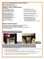
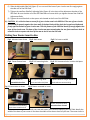
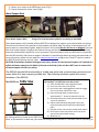
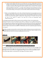
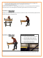
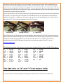
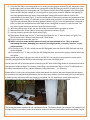
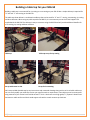
TORONTO TOOL MANUFACTURING INC. SRG-50 User Guide SRG -50 User Manual Version 09:08:12:05 User Guide SRG-50 (Portable Saw and Router Guide System) USER GUIDE: Thank you for purchasing the SRG-50 (Portable Saw and Router Guide System). Below you will find safety procedures, SRG-50 set-up procedures and operating instructions. There is also a section dedicated to available accessories for the SRG-50. For video demonstrations, be sure to visit the “How To” section of our web site www.torontotool.com for the SRG-50 Seminar “how to” video. The patent pending design of the SRG-50 is designed for the "woodworker on the go”. The SRG-50 is professionally designed for accurate cross cutting, rip cutting, miter cuts and routing all lumber up to full 4’ x 8’ sheets. The SRG-50 has the full functionality of a table saw, miter saw, crosscut saw, panel saw and “X”, “Y” router table all in one compact portable tool. You supply the quality circular saw or router and the SRG-50 system supplies the rest. The best part, the SRG-50 is completely portable with a fold up legs and wheels. Never before has there been such a practical woodworking tool that provides ease of use, accuracy, and multiple capabilities in one portable tool with the quality and rugged construction of the SRG-50. The SRG-50 will easily fit in a small mini-van or SUV. Not only is the SRG-50 easy to store and quick to set up, you can take it to the job site or cottage to complete all those jobs you have wanted to do. The SRG Sled, included with the SRG-50, slides effortlessly along the top clamp channel to any position and locks in place for rip cutting or routing any size panel or board up to a full 4’ x 8’ sheet. The accuracy of cut provided by the SRG-50 is equal to any high quality large table saw or CNC Router available in the market. Cross cutting panels provides greater accuracy on the SRG-50 than a standard table saw. The SRG-50 allows you to move the saw against a cut fence for cross cutting rather than struggling to move a panel into a blade as on a table saw. In addition, the SRG-50 comes with a remote power switch, SRG Sled, trigger lock, router insert, 2 router guide stops and 2 panel lock stops that are also used as an angle lock. The contents of this manual are subject to change without notice. For any updates or improvements please visit our web site at: www.torontotool.com 1|Page For Your Own Safety Read Instruction Manual Before Operating Tool Save it for future reference GENERAL SAFETY PRECAUTIONS (For All Tools) 1. KNOW YOUR POWER TOOL. Read the owner’s manual carefully. Learn the tool’s applications and limitations, as well as the specific potential hazards particular to it. 2. KEEP GUARDS IN PLACE and in working order. 3. REMOVE ADJUSTING KEYS AND WRENCHES. Form habit of checking to see that keys and adjusting wrenches are removed from tool before turning it on. 4. KEEP WORK AREA CLEAN. Cluttered areas and benches invite accidents. 5. DON’T USE IN DANGEROUS ENVIRONMENT. Don’t use power tools in damp or wet locations, or expose them to rain. Keep work area well lit. Don’t use tool in presence of flammable liquids or gases. 6. KEEP CHILDREN AWAY. All visitors should be kept safe distance from work area. 7. MAKE WORKSHOP KID PROOF with padlocks, master switches, or by removing starter keys. 8. DON’T FORCE TOOL. It will do the job better and safer at the rate for which it was designed. 9. USE RIGHT TOOL. Don’t force tool or attachment to do a job for which it was not designed. 10. WEAR PROPER APPAREL. Do not wear loose clothing, gloves, neckties, rings, bracelets, or other jewellery which may get caught in moving parts. Nonslip footwear is recommended. Wear protective hair covering to contain long hair. Always wear safety glasses. SPECIFIC SAFETY RULES DO NOT let comfort or familiarity with product (gained from repeated use) replace strict adherence to safety rules. If you use this tool unsafely or incorrectly, you can suffer serious personal injury. Setting up your SRG-50 for the first time: Figure 1a Figure 1b The following steps show how to set up and check the calibration of the SRG-50. 1) Unpack the SRG-50 and place it on the floor 2) Loosen the “T Lock” knob, located on the front rail between the folded legs of the SRG-50, and turn the t-lock to allow the legs to fold down. 3) Pull on the rings of the four folding leg lock pins so they are clear of the folding legs 4) Lift the machine on one end to allow the legs to fold down and rest against the leg stops (figure 1a) 5) Insert the Leg Lock Pins into the leg supports located on both sides of the legs (figure 1a) 6) Tighten the leg lock located on the side of the SRG-50 (figure 1a) 2|Page 7) Lift the machine on the opposite end to allow the legs to fold down and rest against the leg stops (Figure 1b) 8) Insert the Leg Lock Pins into the leg supports located on both sides of the legs (figure 1b) 9) Tighten the Leg Lock located on the side of the SRG-50 (figure 1b) 10) Install the wheels on the axles located on the left and right sides of the SRG-50. Place an inner ½” washer on the wheel axle, slide the wheel onto the wheel axle, place an outer ½” washer against the wheel and install the cotter pin in the 1/8” hole of the wheel axle. Using a pair of plyers, bend both sides of the cotter pin over the axle. Checking Calibration Your SRG-50 has been calibrated and tested at our facility but it is advisable to recheck calibration to be sure the calibration did not come out of adjustment during shipping. There are three calibration adjustment points on the SRG-50. a) The side fence squaring adjustment b) The side fence swivel bolt c) Roller guide adjustment Side Fence Squaring Adjustment: Figure 2 1) The side fence comes pre-squared from our facility but you should check for square by holding a 2 foot square against the cut rail (top clamp) and the side fence. If squaring is required, loosen the Jam Nut (figure 2) on the Side Fence Calibration Bolt (figure 2) and adjust the Calibration Bolt as necessary. Tighten the Jam Nut on the Calibration Bolt and re-check for square. 2) Side Fence Swivel bolt: The side fence has been adjusted at our facility but it is a good practice to check the adjustment from time to time. The side fence should have very little play in a rocking motion therefore some resistance in movement is normal when moving out of the 90 degree position. If there is excessive rocking back 3|Page and forth then, using an Allen wrench and a 9/16” wrench, tighten the lock nut on the underside of the swivel bolt. Do not over tighten the swivel bolt to the point it raises the side fence away from the frame of the SRG-50. A good rule of thumb: Adjust the side fence swivel bolt so you can just slide a piece of paper between the underside of the side fence and the frame of the SRG-50. Roller Guide Clearance Adjustment It may be necessary to adjust the clamp guide roller clearance for one of two reasons: a) the top clamp is difficult to open or close. b) too much play or movement horizontally from front to back Follow the procedure listed below to calibrate both the left and right sides of the clamp guide: ****Note>> Be sure not to adjust the guide rollers too tight. When the guide rollers are properly adjusted there should be almost no movement of the top clamp front to back however the clamp should pivot in an up and down motion to allow the SRG Sled to pivot in the clamp guide for rip cutting. The pivot action of the top clamp guide allows the SRG Sled to slide on the material to be rip cut. This in turn allows the SRG Sled to become a rolling clamp to hold your material down while rip cutting. This is an important feature of the SRG-50 as explained further in the section under Rip Cutting. Figure 3 1) Loosen the Clearance Adjustment Nut (figure 3). 2) Place a 0.020” feeler gauge between the Outer Guide Roller and the guide rail it rolls against. (Note: For reference, 0.020” is the thickness of a typical retractable blade in your utility knife) 3) Press the Outer Guide Roller (figure 3) tight against the feeler gauge while holding Inner Guide Roller (figure 3) tight against the guide rail. 4) Tighten the Clearance Adjustment Nuts (figure 3). 5) The Inner Guide Roller should be able to turn when the top clamp is in the closed position. The horizontal movement of the cut fence should be no more than 0.020 of an inch 6) IMPORTANT: After your adjustment, be sure there is next to no movement of the top clamp in a horizontal motion front to back but still allowing the top clamp to pivot in an up and down motion. This will allow the SRG Sled to rest firmly on the product for rip cutting. The SRG Sled is designed to be a “rolling clamp”. If the guide rollers are adjusted too tight, it will prevent the SRG Sled from making full contact with the material you are rip cutting. For more on this, please refer to the section for rip cutting. 4|Page Setting up the SRG Sled to fit your circular saw It is important to select the correct blade for rip cutting. Please refer to the section “Choosing a Cutting Blade for Your Saw”. Figure 4 Figure 5 1) Locate the SRG Sled included with the SRG-50 One saw we have found to perform well is the Makita model number 5007MGA and the router is a Makita model number RF1101. Another is the Hitachi C7BMR saw and Hitachi KM12VC Router. These pairs allow the router to be interchangeable with the saw without adjusting the SRG Sled. 2) It will be necessary to raise the height of the blade on your circular saw to clear the Rear Saw Lock of the SRG Sled. There are (2) rear lock screws of different lengths included with the SRG-50. Choose the lock screw length that best fits your circular saw. Check for fit of your circular saw in the SRG Sled. To load your circular saw into the SRG Sled, loosen the two Front Saw Locks (figure 5) and the Rear Saw Lock (figure 4) of the SRG Sled. Slide the front of your circular saw base under the two Front Saw Locks as shown in (figure 5). Be sure the base of your circular saw sits flat in the SRG Sled and the sides of the SRG Sled rest firmly against the side frame of the SRG Sled as shown. Slide your circular saw backwards and into the Rear Saw Lock of the SRG Sled (figure 4). Check to be sure the base of your circular saw is completely captured on the rear of the saw base and tighten the Rear Saw Lock (figure 4). The rear lock screw is designed to be hand tightened only. Tighten the two Front Saw Locks (figure 5). Check to be sure your circular saw is securely locked into the SRG Sled. There should be no play from side to side or back to front. 3) If the sides of your circular saw base do not fit perfectly and snugly against the side rails of the SRG Sled then adjustment is necessary by following the next few steps. Caution: It is critical to be sure the base of your circular saw is fully captured by the rails and locks of the SRG Sled. When properly adjusted there should be no movement from side to side or back to front of your circular saw in the SRG Sled. 4) To adjust the SRG Sled to your circular saw, loosen the two Rear Side Rail Adjusting Bolts (figure 4) located in the slot of the adjustment bracket. ONLY LOOSEN the two bolts in the slots and DO NOT loosen the two bolts in the opposite side rail. These two bolts have been set at our facility so the SRG Sled is square to the side fence. Only adjust these two bolts if it becomes necessary to square the side frame of the SRG Sled to the Side Fence of the SRG-50. 5) Loosen the Side Rail Front Adjusting Bolt (figure 5) located towards the front of the SRG Sled. 5|Page 6) Slide the Adjustable Side Rail (figure 5) in or out until the base of your circular saw fits snugly against the side rails of the SRG Sled. 7) Tighten the two Rear Side Rail Adjusting Bolts (figure 4) in the slots of the adjustment bracket of the SRG Sled. Be sure the side rail of the SRG Sled does not move while you tighten the two Rear Side Rail Adjustment Bolts. 8) Tighten the one Allen bolt on the spacer axle located at the front of the SRG Sled. 9) CAUTION: It is critical to have a secure fit of your circular saw in the SRG Sled. The rear of your circular saw should fit squarely against the inner wall of the back lock with the back lock screw hand tightened firmly against the base of your circular saw. The side frames of the SRG Sled should fit snugly against the base of the circular saw. The base of the circular saw must extend under the two front cantilever locks to allow the locks to capture the base of the saw to lock it into the SRG sled. Cutting Your Router Insert to Size Fig 1 Measure base of saw Fig 2 Mark Insert Fig 3 Cut insert to width Fig 4 Center Router base Fig 5 Drill mounting holes Fig 6 Drill clearance holes in white skid plate Mount Router on smooth black surface. Drill right through black insert and white skid plate Fig 7 Screw router to insert Spacers allow for longer standard bolts without countersinking Fig 8 Router mounted to insert Router mounted to shiny The head of the mounting smooth surface of insert bolt clears the white skid The SRG Sled is designed to fit both your saw and router insert without adjusting the SRG Sled. Ideally the plate width of the base of your router is less than the width of the shoe or base of your saw. The router insert is 6|Page manufactured to the correct length for the SRG Sled however the width of the router insert will be determined by the width of your saw base. ****Before you cut your router insert to size it is important to follow the steps below to determine if both your saw and router will be interchangeable. 1) With the SRG Sled adjusted to fit your saw exactly, place your router in the sled to be sure your router base will fit within the side frames of the SRG Sled. If this is the case, then follow the steps below. 2) Measure the exact width of the shoe (base) of your saw (Fig 1). This measurement will become the exact width of your router insert. 3) Measure TWICE and cut once. It is best to place a piece of masking tape on the router insert to give you a clear mark for cutting your router insert to size as shown in (Fig 2). The Router mounts to the shiny smooth surface of the router insert. The white skid plate is mounted to the yellow ring of the insert using 3 spacers. You can now use longer standard pan head bolts to mount your router without the need to countersink the router mounting bolts. If it is necessary to remove the white skid plate for cutting the black insert, be sure to re-install the white skid plate with the 3 spacers and in the same orientation. It is important to mount the router to the shiny smooth surface of the router insert to secure the yellow center ring in place. 4) It is important to have the center hole of the router insert an equal distance from both side frame rails of the SRG Sled. The center hole of the router insert must be centered in the SRG Sled therefore you will cut the router insert an equal amount on both sides. For example. If the base of your saw is 7” then your router insert will also be 7” and the center hole of the router insert will be exactly 3-1/2” on/center. After you have cut your router insert to the correct width, you can now mount your router to the router insert by following the instructions below. 1) Remove the base ring of your router to use as a template to drill the holes in the router insert (Fig 4). There are generally 3 screws that hold the base of your router to the router itself. The SRG Router Insert mounts directly to your router and replaces the plastic router base that you removed. NOTE: Before you drill the mounting holes in the router insert, be sure to orientate your router in such a way as to have the router handles facing in the direction that works for you (Fig 8). 2) Place the router base so the center hole of the router insert is exactly equal to the center hole of the router base (Fig 4). It is best to clamp your router base to the router insert before you drill the three mounting holes in the router insert (Fig 4). 3) Using a sharp drill bit the same size as the holes in your router base, drill the three mounting holes in the router insert and straight through the white skid plate (Fig 5). 4) Drill clearance holes in the white skid plate of the router insert so the router mounting screws are flush with the underside of the black router insert (Fig 6). If possible, it is best to replace the existing router mounting screws with longer screws to mount your router to the router insert. This allows you to avoid countersinking the mounting screws in the black router insert. If you use the existing screws that came with your router then it will be necessary to countersink the screw holes in the router insert to give you sufficient thread to mount your router (Fig 6). CAUTION must be taken here. DO NOT drill the counter sink holes any deeper than necessary. You want the screws just flush with the surface of the SRG Router Insert with sufficient thread on the screws to mount your router to the SRG Router Insert. Be careful not to allow the countersink holes to go all the way through the router insert. 7|Page 5) Mount your router to the SRG Router Insert (Fig 7). 6) Router mounted to router insert (Fig 8) Wood Support Rails Three Wood Support Rails Using rail as a measurement guide for rip cutting as described Three wood support rails (included with the SRG-50) are designed to support your material when rip cutting. The rails can be moved to any position to fully support your panel while rip cutting. A wood support rail can also be used as a measurement guide. Mount the saw in the rip sled (Be sure the saw is un-plugged), rest one side of the wood support rail against the blade of the saw and use the built-in measuring scale to accurately locate the measurement required to rip cut your panel. The wood support rail(s) are also used in conjunction with the SRG Auxiliary Side Fence to support a board as it is feed through when rip cutting narrow boards. For more information, please visit our web site www.torontotool.com and go to the “How To” section to watch the SRG-50 demonstration seminar video. CAUTION: A hazardous situation causing personal injury. Always be sure the wood support rail is placed at a sufficient distance away from the blade of the saw so the blade of the saw does NOT come in contact with the wood support rail when rip cutting. The SRG-50 has the full functionality of a table saw, miter saw, crosscut saw, panel saw and router table all in one compact portable tool. The following sections explain the various functions of the SRG-50. The SRG-50 is a Table Saw Accurately rip cut large panels. Rip cutting 4’ x 8’ sheets has never been easier. 1) Place the SRG Sled in the top guide channel 2) Insert a circular saw in the rip sled 3) Be sure the saw is unplugged and install the trigger lock on the power switch of the saw 4) Raise the clamp height on both sides to approximately ¼” above the material to be cut 5) All measurements are made from the blade of the saw to the side fence 6) Slide the SRG Sled along the guide track to the required measurement and lock the SRG Sled in place 7) Plug the circular saw into the remote power switch 8) Be sure the circular saw power cord is out of the way of the material when cutting 9) Make the cut. Rip cutting panels or boards on the SRG-50 performs the same way as a table saw. Instead of moving the side fence, as you would on a table saw, you move the cutting tool on the SRG-50. The same rules for rip cutting on 8|Page a table saw apply to rip cutting on the SRG-50. Such as with a table saw, it is important to keep your product firmly against the side fence when pushing material through the blade. Choosing a Cutting Blade for Your Saw: The most important aspects in choosing a rip cutting blade for the SRG-50 and Pro-Cut 50 is the number of teeth on the blade and the amount of flex in the blade. In addition to using a quality circular saw, the blade selection is equally important and some may argue more important than the saw itself. It is recommended to use a blade with 40 teeth for rip cutting with a minimum amount of blade flex. Be sure to set the depth of cut to no more than 1/4" below the material to be cut. The blade determines the quality and ease of cut. A 40 tooth carbide tipped blade with a minimum amount of blade flex will provide smooth cuts and is considered a good general purpose blade for both cross cutting and rip cutting. The amount of flex in the blade along with the blade depth will determine the accuracy of cut. There should be a minimum amount of blade flex to prevent the blade from flexing or wandering during the rip cut. Excessive blade flex will result in binding and most likely produce a wavy cut. The same rules for rip cutting on a table saw hold true for rip cutting on the SRG-50 and the Pro-Cut 50 and therefore you will want to choose a blade with a minimum amount of flex. To determine the amount of flex in a blade you simply press both thumbs to the center hole of the blade while flexing the blade on the outer edges. If the blade is easy to flex then you should avoid using this blade and select a blade that is more rigid. It is also important to set the depth of cut to not more than ¼" below the material you are cutting to avoid blade binding. This is a standard practice with any cut on any tool such as a table saw, the SRG-50 and Pro-Cut 50. To adjust the depth of cut, simply adjust the depth of cut on the circular saw. Tip: If material requires excessive pushing force to feed while rip cutting, binds and/or burns the material, it is likely due to a dull blade, excessive blade flex or the blade depth is set to low. A saw blade that flexes while rip cutting will result in the blade wandering, binding and possibly burning of the material. The most visible result of excessive blade flex is a wavy rip cut even though the material was held tight against the side fence and fed squarely through the tool. To avoid this situation use a sharp blade with a recommended 40 tooth configuration. It is also recommended to select a blade with a minimum amount of blade flex. Be sure the blade depth is set to no more than ¼" below the material you are cutting. To set the depth, adjust the depth of cut on the circular saw. Avoid using rough cut blades such as 18 tooth blades with excessive blade flex. This will result in poor cut quality, excessive tear-out, wavy cuts and excessive binding that makes it very difficult to push material through the tool while rip cutting. For rip cutting veneered plywood such as oak or melamine you will want to use at least a 40 tooth blade with minimal amount of blade flex. A 50 to 60 tooth blade will provide an even cleaner cross cut on grained wood, veneer plywood and melamine to further minimize tear-out. Always make sure your blade is sharp as a dull blade will burn the wood and cause poor, uneven cuts. Below are step by step instructions for rip cutting: 1) Adjust the top clamp so it is approximately ¼” higher than the material to be cut. In some cases, such as with warped construction grade plywood, it may be necessary to raise the clamp to approximately ½” above the thickness of the material to be rip cut. The important point is to be sure the clamp opening is the same height on both the left and right side of the SRG-50 clamp. 2) Position the 3 wood support rails in any position but making sure a wood support rail will not come in contact with the cutting blade of the saw. Before you place the SRG Sled on the guide, ensure the 9|Page product to be rip cut is able to move freely through the tool. You should have any accessories such as feather boards in place when testing the movement of the panel. As with any tool, it is important to use in-feed and out-feed supports when rip cutting large panels. The SRG Roller Stands are perfect for this application and were designed specifically for the SRG-50 and Pro-Cut 50 but they can be also used for many different applications. We consider the SRG Roller Stands to be among the best roller stands available on the market. 3) Place the SRG Sled on the guide channel and install the circular saw, be sure the saw is un-plugged and install the trigger lock to lock the switch of the saw to the “ON” position. Plug the saw into the remote power switch box of the SRG-50. Be sure the power cord of the saw will not interfere with the panel as it is moved through the SRG-50. The power for the saw will be turned on and off using the power switch mounted on the SRG-50. 4) If you want to rip cut a panel at an angle simply set the blade to the desired angle on the saw. 5) There are a variety of ways to set the rip sled for the width of the material you want to rip cut. a) You can use the built-in scale of the SRG-50 by placing one of the wood support rails squarely against the blade of the saw, move the SRG Sled back and forth to line the wood support rail up with the exact measurement as read from the built-in scale of the SRG-50. When you have desired measurement, lock the SRG Sled to the guide channel using the two lock knobs. b) Be sure the saw is unplugged. Measure and make a mark on the end of the panel or board for the width you want to cut. Slide the panel or board under the SRG Sled skid rails and up to the blade. Line your mark up with the blade of the saw and then lock the SRG Sled to the clamp guide channel using the two lock knobs. Be sure to back up your panel so the blade of the saw is not in contact with the panel to be rip cut when you turn the remote power switch to the “on” position. c) Using a tape measure, measure directly from the blade of the saw to the side fence. Slide the SRG Sled along the clamp guide channel to the desired location and lock the SRG Sled in place. An advantage of the SRG-50 is that the SRG Sled becomes a “rolling clamp” to prevent your product from lifting such as can be frequently experienced on a table saw. Most people refer to this as “riding the blade” which can result in kick back. This is especially true when rip cutting thinner panels such as ¼” plywood. With the “rolling clamp” of the SRG-50 taking care of this issue you only have to concentrate on pushing the panel squarely through when rip cutting. There are a variety of ways to ensure the material is held firmly against the side fence when rip cutting. Always use the included wood support rails to support a board or panel when rip cutting. Select the correct blade for rip cutting. Please refer to the section “Choosing a Cutting Blade for Your Saw”. a) Developing a technique is important for pushing the panel forward through the blade while also pushing the material against the side fence. Generally you would use the right hand for pushing the material forward through the blade while using the left hand, placed on the side of the material, to push the material against the side fence. Be sure the panel is kept against the side fence by only using enough side-ways pressure to keep the panel against the side fence. Too much side-ways pressure may result in the panel moving away from the side fence on the blade end. 10 | P a g e b) You can use the Auxiliary Side Fence in one of two ways to act like a feather board. 1) Rest the auxiliary side fence against the side of the panel to be rip cut and clamp the Auxiliary Side Fence to the back rail. Use your right hand to feed the panel through the SRG-50 while using your left hand to push the auxiliary side fence against the side of the panel to be rip cut which in turn holds the panel firmly against the side fence. 2) In some cases the panel you are rip cutting may not have a square edge in which case you may not be able to clamp the Auxiliary Side Fence to the back rail as this may cause binding. In this case you can use the same method as above without clamping it. 6) When you have decided which of the above methods will work best for the material you are rip cutting, you simply slide the material up to and just under the skid rails of the SRG Sled but short of the saw blade, turn the power on using the remote power switch of the SRG-50 and make the cut. Like any new tool it may take a little practice to perfect your cutting techniques. For further information you can refer to the “HOW TO” section of our web site to view the informational videos. www.torontotool.com For rip cutting narrower boards it will be necessary to use an auxiliary cut fence. You can purchase the optional SRG Auxiliary Cut Fence by visiting your local retailer or ordering it on-line at www.torontotool.com. The auxiliary cut fence is a spacer to take up the distance from the side fence of the SRG-50 to the blade of the saw. The SRG-50 Auxiliary Cut Fence is 36” long with aluminum side rails and has a heavy duty toggle clamp to lock the auxiliary cut fence in place. The toggle clamp is secured to the underside of the auxiliary side fence and locks in place to the back rail of the SRG-50. The SRG Auxiliary Cut Fence is explained in greater detail later in this manual. TIP: When you require a next to perfect cut and to further minimise chipping or tear out on material such as veneered plywood and melamine you can use a sharp utility knife to pre-score the material along the cut line. To further reduce tear-out you can also place masking tape over the cut line. Trigger Lock Caution: Always be sure the saw is unplugged before installing the saw trigger lock To install the saw trigger lock, open the screw knob of the lock to allow it to fit over the trigger of the saw with the hook of the trigger lock capturing the trigger of the saw. Tighten the trigger lock screw knob against the handle of the saw to engaged power. Plug the saw into the remote power switch. The remote power switch is now used to turn the power for the saw on and off. 11 | P a g e CAUTION: Never place your fingers under the base of the circular saw or in close proximity to the blade in any circumstance when rip cutting or performing any other application. This may result in serious injury. When rip cutting, always use a push stick to complete the rip cut of all material. The SRG-50 is a Cross-Cut Saw Cross-cut single or multiple panels up to 49” wide at the same time The SRG-50 is a perfect tool for cross cutting full 4’ x 8’ sheets Measure, clamp and cut........ it’s that simple. The SRG-50 is the best and most accurate portable tool on the market for cross cutting large panels. Measure where you want to cut the panel(s) or board(s), slide the panel or board through the clamp, measure from your cut line to the cut fence, close the clamps and make the cut. CAUTION: The top clamp is designed to flex under pressure but do not over-tighten the clamp screws. The clamp screws are able to supply sufficient and excessive pressure to permanently warp the top clamp when the product you are clamping is thick enough to allow excessive downward travel of the top clamp and well beyond the required clamping pressure. You will find that a small amount of pressure is all that is required to tightly hold the product you are clamping. The clamp is manufactured with structural steel and, in the event the top clamp does become warped, you can remove the top clamp to straighten it. TIP: The panel lock (supplied with the SRG-50) can also be used to hold the material to be cross cut to prevent any possible movement of the product when cross cutting single or multiple boards or panels. To use the angle lock for this application, place your material to be cross cut squarely against the side fence of the SRG-50 and slide the panel lock along the back rail of the SRG-50 until it just contacts the side of the material to be cross cut. Secure the panel lock in place by tightening the panel lock screw knob against the back rail. The panel lock now captures the material to be cross cut against the side fence and ensures the material will not pivot when cutting. For further information, please visit our web site www.torontotool.com and go to the “How To” section to watch the SRG-50 demonstration seminar video. There are various ways to measure from the cut line to the cut fence but the fastest and easiest way is to make a measuring block. The measuring block is cut to the exact distance from the blade of the saw to the edge of the base or shoe of the saw. You would use the same method to make a measuring block(s) for your router. Using a measuring block: 1) Measure where you want to cut your panel or board 2) Slide the panel or board through the clamp and against the side fence 12 | P a g e 3) Place the measuring block against the cut fence and slide the panel or board to the edge of the measuring block making sure the material is tight against the side fence. 4) Close the clamp and make the cut. Because the material to be cut is squared against the side fence, it is only necessary to mark one location on your panel to be cut. The measuring block is discussed in greater detail at the end of this user guide. The SRG-50 is a Panel Saw By design, the SRG-50 allows one to rip cut and cross cut full 4’ x 8’ sheets. This functionality replicates all the features and benefits of a large panel saw. The SRG-50 is a Miter Saw To set the side fence to any desired angle 1) Find the measurement that corresponds to the desired angle using the angle chart. 2) Move the side fence to the measurement ( use the top of the 1/16” scale as shown) 3) Lock the side fence to the desired measurement using the panel lock Using the chart, the side fence is locked at 16” = 50o 13 | P a g e The side fence of the SRG-50 pivots to any miter angle. The most common miters used in woodworking are 45o and 22-1/2o. The SRG-50 has position pin locks for both of these miter angles. For all other miter angles, refer to the miter angle chart attached to the SRG-50. The chart shows an angle on one side and an exact scale measurement for that angle on the other side. Simply move the side fence to the scale measurement and lock the side fence in place using the panel lock. To lock the side fence at 45o, unlock the side fence from the 90o position and move the side fence towards the 45o position. Line up the 45o hole in the back rail of the SRG-50 with the 45o hole position on the side fence and insert the lock pin. In addition to the lock pin, you can also use the included panel lock to firmly lock the side fence at 45o. Follow the same procedure for the 22.5o location. Lock pin at 45o Lock pin at 22-1/2o Fig.7 panel Lock For all other miters, set the side fence to the desired angle, place the panel lock (Fig.7) on the back rail of the SRG-50 with the screw knob facing down. Lock the side fence at the desired angle by capturing the side fence rail against the back rail and tighten the screw knob of the panel lock. For a complete video seminar demonstration of the SRG-50 operation, please refer to our web site under the “How To” section. www.torontotool.com The following conversion chart converts a measurement (using the build-in scale of the SRG-50) to degrees. 5o 7.5o 10o 12.5o 15o 17.5o 20o 22.5o = = = = = = = = 1-3/16” 1-3/4” 2-5/16” 2-7/8” 3-1/2” 4-1/8” 4-3/4” 5-7/16” 25o 27.50 30o 32.5o 35o 37.5o 40o 42.5o = = = = = = = = 6-1/8” 6-7/8” 7-5/8” 8-3/8” 9-1/4” 10-1/8” 11-1/8” 12-1/8” 45o 47.5o 50o 52.5o 55o 57.5o 60o = = = = = = = 13-3/8” 14-5/8” 16” 18-1/2” 19-1/8” 21-1/8” 23” The SRG-50 is an “X” and “Y” Axis Router Table It is easy to perform many routing tasks including some tasks that can’t be done on any other tool. 14 | P a g e (Fig 1) (Fig 2) (Fig 3) You can perform countless router applications using the “X” and “Y” capabilities of the SRG-50. As an example, the SRG-50 is set up to router cabinet doors as shown in (Fig 1) and, as shown in (Fig 2), set up to router shelf dados in both sides of a cabinet. The following are easy basic set-ups for routing on the “X” and “Y” axis. Most every set-up is generally the same as shown below. Basic Set-Up for Routing on the “X” and “Y” Axis Table Top Clamps Clamps (Fig 4) (Fig 6) Guides (Fig 5) (Fig 7) Clamp Screw Place spacer block here clamp opening is the same on both sides 15 | P a g e Clamps Layout Marks Layout Mark (Fig 8) (Fig 9) (Fig 10) In the set up shown above, we have clamped a table top to the SRG-50 using standard “C” clamps. 1) The table top is squared against the SRG-50 side fence and clamped to the opposite end of the SRG-50 frame using a 2” “C” clamp (Fig 7). The table top shown here is 30” x 48” x 5/8” thick. We selected a table top material that allows for low resistance for sliding project material back and forth. 2) You can use any material for the 2 guides but we purchased a couple of 8” shelves with finished edges to allow for easy sliding of project material. Note: The guides you use should be twice the length of the project material length. For example: if you are routing cabinet doors that are 2’ in length, then the guides should be at least 4’ in length as shown above. 3) Place one of the guides squarely against the side fence and clamp it in place using 2 “C” clamps (Fig 4, Fig 5). We used a 2” “C” clamp on one end and clamped it to the table top. We used a 4” “C” clamp to clamp both the guide and the table top on the other end of the guide over the side fence and to the frame of the SRG-50 as shown above (Fig 4, Fig 5). 4) Place your project material squarely against the guide (Fig 4). 5) Place the second guide against your project material and clamp the guide in place (Fig 5). Be sure you can slide your project material back and forth within the guides but that the guide is tight enough to prevent any rocking motion of your project material when you slide it within the guides. 16 | P a g e 6) Place the SRG Sled in the clamp guide so it is resting on your project material (Fig 10). Adjust the clamp guide height evenly on both sides of the clamp guide so the SRG Sled just starts to lift away from your project material on the clamp guide side. This ensures the SRG Sled is fully engaged in the clamp guide. Lower the SRG Sled just enough so it is resting flat on your project material. Measure the opening of the clamp guide between the lower clamp and upper clamp guide on both sides to confirm the measurement is the same (Fig 6). To lock the clamp guide in place and to prevent any movement of the clamp guide while routing, it is advisable to cut a spacer block and lock it in place with the clamp screw (Fig 6) on the indicated end of the clamp guide as shown in (Fig 6). Once the spacer block is clamped in place, re-check the measurement on both sides of the clamp guide to ensure it is still the same. You can use the spacer block over and over again for future set-ups. 7) With the guide system set up, you are now ready to measure where you want to router. 8) Measure and mark all four sides of your project material as shown in (Fig 8) 9) Line the router bit up with the layout marks (Fig 9) 10) Place Router Guide Stops for the “X” Axis and Panel Stops for the “Y” Axis as shown in (Fig 10). The SRG-50 comes with 2 Router Guide Stops and 2 Panel Stops. 11) Turn on the router and make your cut. 12) NOTE: It is best to make multiple passes to reach your desired depth of cut. This is to prevent overloading the router, damaging your router bit, burning the wood, or causing “chip-out” in your project material. 13) For routing on the “X” Axis, unlock the two SRG Sled guide locks and slide the SRG Sled back and forth within the guide. 14) For routing on the “Y” Axis, lock the two SRG Sled guide locks and move the project material within the two guides. Making raised panel doors is also an easy task on the SRG-50. You can glue a second panel to a door panel, raise the clamp guide of the SRG50 to the new height and router the raised panel. You can also end mill or decorate panels or boards up to 49” wide. End milling allows for a professional look to inset panels to hide the edges. For example, end milling is the professional way to inset a ¼” back panel into the sides, top and bottom of any cabinet. Measure, clamp and router......it’s that easy. Shown below is a set up for routing dados in both side panels of a cabinet. We have clamped the two panels on the end so they stay perfectly positioned. You can also router dados in just one sheet and rip cut the panel to make the two side panels after the routing is completed. For this application, router guide stops are positioned on the clamp guide rail of the SRG-50 to stop the router at the desired locations. This set-up guarantees a perfect fit and a professional look. This feature allows, for example, the installation of multiple shelves or any other project that requires material to be inset into another panel using dados. To give 17 | P a g e a professional look to all your projects such as bookcases, custom kitchen cabinets or display cabinets, it is always recommended to inset shelves using dados. You can also make unlimited lengths of custom moldings by using the same basic guide system as show above. Calibration of the SRG Sled It may be necessary to re-calibrate the SRG Sled on occasion. To do this you will need two 9/16” wrenches. 1) Set up the SRG Sled following the instructions in step (6) above so the SRG Sled is resting flat on project material with the SRG Sled fully engaged in the clamp guide. This step is important because the rail of the clamp guide is slightly tapered to allow for easy removal and placement of the SRG Sled. 2) Place a 9/16” wrench on the lower nut of the SRG Sled roller bearing assembly and loosen the top nut using a second 9/16” wrench. 3) Loosen the roller assembly on the other side of the SRG Sled using the same method. 4) Place a 1/1000” feeler gauge between the roller bearings and the clamp guide on both sides of the SRG Sled. (Note: a piece of 20 pound bond paper is approximately 1/1000”) 5) With a 9/16” wrench placed on the bottom nut of the roller assembly, gently push the assembly against the feeler gauge and tighten the top nut of the roller assembly using the second 9/16” wrench. 6) Perform the same operation for the roller bearing assembly on the other side of the SRG Sled. 7) Remove the 2 feeler gauges. 8) Check to be sure the SRG Sled slides smoothly along the clamp guide with no rocking movement. (Note: the tighter you make the tolerance, the more resistance there will be in moving the SRG Sled back and forth on the clamp guide). If there is excessive resistance when moving the SRG Sled back and forth then it may be necessary to re-calibrate the roller bearing assemblies. Optional SRG Auxiliary Side Fence Fig.6 Used for rip cutting narrow boards on the SRG-50. The SRG Auxiliary Side Fence is a spacer to take up the distance from the blade of the saw to the side fence of the SRG-50. The auxiliary side fence is placed against the side fence of the SRG-50 and clamped to the back rail of the SRG-50 with the toggle clamp of the Auxiliary Side fence as shown in Fig. 6 It is always recommended to use the Wood Support Rail (included with the SRG50) when rip cutting boards. The Wood Support Rail will support the board as you feed the board when rip cutting. Refer to the section on Rip Cutting of this user manual for further instruction for rip cutting. You can also view the “How to” section of our web site www.torontotool.com for instructional videos. 18 | P a g e Building a table top for your SRG-50 Building a table top is not essential for rip cutting or cross cutting on your SRG-50 but a simple table top is required for “X” axis and “Y” axis routing on the SRG-50. The table top shown below is a combination table top that can be used for “X” and “Y” routing, crosscutting, rip cutting and dust collection. When using any table top with the SRG-50, it is not necessary to use the 3 steel support rails supplied with the SRG-50. The table top is easy to construct using the SRG-50 and will provide additional benefits for cross cutting, rip cutting and dust collection. Table top Table top set up for rip cutting Set up with router in sled Set up for Crosscutting We have provided detailed step by step instructions and measured drawings along with a cut list to build a table top. You can easily modify your table top to suite your specific needs or requirements. Your table top can be constructed using material of your choice but should be at least ¾” thick. We chose to use high grade, ¾” plywood. We will later laminate our table surface and the 4 wood support rails with a smooth counter top laminate. 19 | P a g e SRG50 Table Underside 20 | P a g e Build List Table top 48” (L) x 36”(W) x ¾” thick Positioning Rail 39” (L) x 2” (W) x ¾” thick Spacer Rails 38” (L) x 2” (W) x ¾” thick (2 required) Bottom plate 38” (L) x 10-1/2” (W) x ¾” thick Wood support rails 7-1/4”(L) x 2” (W) x ¾” thick (4 required) Note: Use the same ¾” material that you made the table top from so the height of the 4 rails are exactly even with the table top. The wood support rails allow material to easily slide across the table top without catching on the lip of the cut-out. Heavy duty toggle clamps (2 required) Counter top laminate 48” x 36” 1 liter, contact cement. Below are step by step instructions for cutting the parts required to make your new table top using the SRG-50. Since this may be your first project using the SRG-50, we have provided additional instructions pertaining to the use of the SRG-50. Note: Most saws measure 1-1/2” from the blade to the side frame of the saw. You will use this measurement for cross cutting until you have the kerf line on your new table top. This is a great project to get you comfortable with the SRG-50. Practice makes perfect and like any new tool it takes a while to become an expert. Measure twice and cut once! Step 1 1) Table Top Using your SRG-50 in the cross cut mode, measure, place, clamp and cut 36” from a 4’ x 8’ sheet of plywood (or material of your choice). NOTE: The 4’ x 8’ sheet should be properly supported on both the in-feed and outfeed. Be sure the material is placed tight against the side fence and allow for the offset of the saw blade when cross cutting. (After completion, your new table top will have a kerf line that allows for fast and easy measurement for cross cutting). NOTE: The SRG-50 has 500 pounds of clamping pressure and has sufficient pressure to damage the wood and even bend the guide rail. Only use sufficient clamp pressure required to securely hold the wood. Generally, one finger will supply 100lbs. of pressure which is generally more than enough to securely hold your wood for cutting. The guide rail is designed to flex up to ½” under pressure which is normal operation. Past that amount of flex, it could damage the guide rail. 2) Positioning Rail, Spacer Strips Wood Support Rails Loosen the clamp screws of the SRG-50 and advance the sheet to cut a 2” strip. Tighten the clamp screws and make the cut. You will need a total of four… 2” strips. We will cut the strips to length later. 3) Bottom Plate Loosen the clamp screws, advance the sheet and cut a 10-1/2” bottom plate. 4) Measure and mark the first 2” strip at 39”. Lock the strip in the clamp and cut to length. 21 | P a g e 5) To cut the (4) 7-1/4” wood support rails to length, you can use the same method as above or your miter saw. 6) Measure the two remaining 2” strips and the 10-1/2” wide bottom plate at 38” long. 7) To show how to cut multiple boards or panels to length with one cut………Place the two 2” strips and the 10-1/2” bottom plate in the clamp and tight against the side fence at 38”. (The ends of the strips and panel should all be even) Close the clamp screws. Only tighten the clamp screws enough to hold the wood. You may see slight flexing of the guide rail, this is normal but DO NOT OVERTIGHTEN THE CLAMP SCREWS. Position the angle lock on the back rail of the SRG against the strips of wood and lock it in place. Make the cut. The additional lock will prevent any possible movement of the multiple boards when cutting. 8) 9) 10) 11) 12) 13) 14) 15) This method of cutting multiple boards is used by many as a huge time saver. You can even double stack ¾” and 1” boards to cut up to 20 boards to length at one time. One generally uses a carpenter square or makes up a squaring jig to quickly even all the ends of the boards before cutting. This method is excellent for cutting multiple boards or studs to length at the same time. This cutting method decreases your cut time by about 2/3 when building a fence, decking, siding, wall studs or any other project that requires multiple pieces. Now that all your pieces are cut it is time to make the cut out in the table top. We will use the router with a ¼” straight bit and the “X” and “Y” functionality of the SRG-50 to make this cut out. Install a ¼” straight cut bit in the router. Be sure the bit extends long enough to cut completely through your ¾” thick table top. Place and clamp a temporary table top in the SRG-50 as shown in the SRG-50 calibration video and the SRG-50 demonstration video. Place and clamp a side guide tight against the SRG-50 side fence. Note: be sure the side guide is long enough to allow the placement of the panel stops as shown in the videos. Place the panel to be routed against the side guide you just installed. Place and clamp a second side guide against the opposite side of the panel to be routed. Note: the panel to be routed should move freely (with slight resistance) back and forth but tight enough to prevent any rocking movement. Measure the four sides of the cut-out on the panel to be routed. (you can refer to the SRG-50 calibration video to view the method of measuring for “X” and “Y” Routing). Make the cut. Because of the excellent precision of the “X” and “Y” router set up on the SRG-50, all four sides of your cut out will be exactly parallel to each other. ASSEMBLY 1) Place the table top in the SRG-50 with the side of the table top squarely against the side fence of the SRG50. 2) Place the saw in the SRG sled and place on the SRG-50 guide rail. Lower the blade of the saw to be sure the blade will extend into the cut out evenly on both sides of the cut-out without obstruction by the cut out. If adjustment is required, move the table top until the blade of the saw slides back and forth on the guide rail of the SRG-50 without obstruction. Tighten the Clamp screws to lock the table top in place. Note: When cutting material, the blade depth of the saw should be set to approximately ¼” below the material you are cutting and therefore in most situations the blade will only extend into the table top cut out by approximately ¼”. Setting the blade depth to approximately ¼” below the material you are cutting is a standard practice in woodworking and ensures a good quality cut, reduces blade binding, reduces heat build-up and extends the life of the blade. Be sure to refer the user manual “selecting the correct blade for your saw”. Use at least a 40 tooth blade that is ridged with virtually no flex like you would use on a table 22 | P a g e 3) 4) 5) 6) 7) 8) 9) 10) 11) 12) 23 | P a g e saw. Thin kerf blades are flexible and tend to follow the grains of the wood resulting in wavy cuts, especially noticeable on long rip cuts. Lower the clamp screws to lock the table top in place so it cannot move. On the underside of the table top, you will see where the table top is resting on the back frame of the SRG50 (opposite side from the clamp screw guide). With a dark pencil, mark the entire length of the frame rail onto the table top. This is where you will glue and screw the positioning rail to the table top. It is advisable to mark some x’s on the side of the line where you will attach the positioning rail. Remove the table top and glue and screw the positioning rail to the table top. Be sure the screws you use to do not go through the table top surface. It is also important to ensure the positioning rail is installed exactly on the line you mark on the table top because the positioning rail determines where the table top will be locked in place when removing and installing the table top. The positioning rail is placed exactly on the line you marked and 61/4” from the SRG-50 side fence side and 2-3/4” from the opposite side of the table top. This spacing will allow room for the toggle clamps. Glue and screw the two 2” x 38” spacer strips to the underside of the table top ensuring there is ¼” lip on both sides of the cut out for the wood support rails. Glue and screw the 10-1/2” bottom plate to the space strips At this point you can cut out a hole in the center of the bottom plate for your dust collection. The center position for your cut out hole is 5-1/4” from the sides and 19” from the ends. Place the table top back in the SRG-50 ensuring the positioning rail is tight against the back frame of the SRG-50 and the side of the table top is tight against the side fence of the SRG-50. Tighten the clamp screws of the SRG-50 to lock the table top in place. Place a toggle clamp as shown in the drawing so it is able to clamp to the frame of the SRG-50. Mark the 4 hole positions on the table top. Repeat this step for the opposite side. Drill the holes (a total of 8 holes for the two toggle clamps). After the holes are drilled, it will be necessary to counter sink the holes on the table surface so the heads of the bolts are below the table top surface. Install the two toggle clamps using nuts and bolts. Note: If you are going to laminate the table top, it is advisable to secure the bolts to the table top with nuts before you install the laminate. Once laminated, you will no longer be able to tighten the nuts and bolts because the laminate will cover the bolt heads. Place the table top back in the SRG-50 ensuring the positioning rail is tight against the back frame of the SRG-50 and the side of the table top is tight against the side fence of the SRG-50. Lock the toggle clamps and tighten the clamp screws of the SRG-50 to lock the table top in place. You will now make your kerf cut. Take your time and care to ensure you make a perfect cut since all future cuts are measured and cut to the kerf cut you will be making. Set the saw depth to ¼”. With the SRG-50 guide rail in the clamped position using the clamp screws, run the saw against the guide rail of the SRG-50 the entire length of the table top to create a kerf cut in the table top. Every time you remove the table top and re-install it, the kerf will fall in exactly the right position. Now you simply mark the material to be cut, line up your measurement to the kerf and make the cut. When you cross cut any material on the SRG-50, follow the rule of setting the saw only ¼” below the thickness of the material to be cut. This will ensure you do not cut your kerf too deep. You can add an additional 3” x ¾” strip to the underside of the kerf if you accidently cut the kerf too deep during subsequent cuts. Optional SRG Roller stands The SRG Roller Stands are ideal when used in conjunction with the SRG-50 as in-feed and out-feed rollers for smooth rip cutting of large panels without assistance. They are also perfect for supporting long boards and planks for cross cutting. The SRG Roller Stands are easy to transport, easy to store and easy to set up. The heavy duty, sturdy construction of the SRG Roller Stands make them ideal for the "woodworker on the go” with their light weight (34lbs.) and compact size of only 4 inches deep when folded. The Roller Stands are fully adjustable in height from 23-1/4” to 37” and can be used for a wide variety of applications. Each roller independently adjusts for height, allowing you an offset from one roller to the next for out-feed applications. A complete SRG System, comprised of the SRG-50 and 2 SRG Roller Stands, is designed for portability and will easily fit in a small mini-van or SUV. The SRG System can easily be stored against a wall in your garage when not in use and quickly sets up into a complete woodworking station for all your woodworking needs. Top Clamp Rubber Pad The SRG-50 comes with a replaceable soft rubber pad that serves two purposes. 1) To provide a firm grip on the work piece when the clamp is in the closed position. 2) To protect the surface of the project from any possible damage or marking while clamped. The rubber pad will last a long time if a few simple precautions are observed. Always be sure the clamp is open enough to allow your work piece to move freely back and forth. Avoid forcing your work piece into the clamp as this may damage the pad. Replacement pads are available from Toronto Tool Manufacturing Inc. The part number and pricing for replacement pads, along with all other parts, are listed in the SRG-50 parts manual in the information section of our web site www.torontotool.com. Please be sure to specify the model you are ordering any parts for. 24 | P a g e Tips for accurate cross cutting: There are basically 3 ways to measure and cut your material on the SRG-50. 1) Using a tape measure, measure the distance from the saw blade or router bit to the edge of the tool. Use this measurement to measure from the saw guide of the SRG-50 (top clamp) to the cut line of the material to be cut or routered. For most circular saws this distance is 1-1/2 inches but the measurement will vary for router bits depending on the bit you are using in your router. By placing the material to be cut in the clamp and against the side fence of the SRG-50, it is only necessary to make one measurement for a square cut. 2) The second method is much the same as the first method with the exception that you use a calliper (either digital or analogue) to provide a more precise measurement. In most cases it is easier and faster to use a calliper. Simply slide the end rod of the calliper from the edge of the tool to the blade of the saw or router bit as shown. Tighten the lock screw on the calliper to retain this measurement. Use this measurement to measure from the cut guide of the SRG-50 to the cut line on your material. 3) The third method saves a lot of time if you use the same saw or router bit on many occasions. This method is simply to use a block of hardwood that measures the exact distance from the blade of your saw or router bit to the edge of the tool. These are called measuring blocks. You can make these measuring blocks by measuring and cutting pieces of hardwood using one of the two methods above. Once you have made your measuring block you place it against the cut guide of your SRG-50 and move your material until the cut line on your material is even with the measuring block. You can use the measuring block over and over by writing a description on the measuring block what tool and blade or router bit you made it for. Lubrication The clamp screws should be lubricated from time to time using synthetic oil. EZoil is the best we have found however you can use any light weight oil. To apply the oil, screw the clamp screws all the way to the top position and apply a few drops of oil around the clamp support where the thread enters the support. As you screw the clamp screws down, the thread will be lubricated . SRG-50 Clamp Width Overall Width Overall Depth Overall Height (legs folded) Overall Height (legs down) Clamp Height (legs down) Clamp Opening Travel Side Fence Adj. Roller Guides Squaring Calibration 8” Wheels Built-in measure scale 50” 56” 24” 17” 37-1/2” 27-1/2” 3-1/2” 36” yes yes yes yes Total shipping Weight 130 Lbs. 25 | P a g e Included Wood Support Rails (3) Angle Lock Saw Trigger Lock Remote Power Switch Box SRG Sled Router Insert Router Guide Stops (2) Panel Stops (2) Included Included Included Included Included Included Included Included Toronto Tool Manufacturing Inc. WARRANTYY (One Year Warranty Applies only to Canada & the United States) Toronto Tool Manufacturing Inc. Warrants Toronto Tool Products- Pro Series®-BT Series and SRG-50 and accessories against any defects in material or workmanship for a period of ONE(1) year from date of original purchase. The original sales receipt is required as proof of purchase for all warranty claims. Providing the product was properly assembled and operated in accordance with the machine operating instructions and further provided the product was not misused or abused. In case of claim, do not return the product to store of original purchase. Call, email or write customer service at Toronto Tool Manufacturing Inc. to describe the nature of the problem. Toronto Tool Manufacturing Inc., at its sole discretion, will evaluate the claim and, where acceptable, provide replacement parts or product. Any replacement parts or machines will be guaranteed only to the extent of the original warranty period. We shall in no event be liable for injuries, accidental or otherwise, death to person or damage to property or for incidental, and contingent, special or consequential damages arising from the use of our products. Not Covered Under Terms of Warranty: Damage due to fire, theft, floods, and/or acts of God, misuse, abuse, negligence or accidents, product has been modified in any way, product used for other than the intended use, improper assembly or operation. Normal wear and tear. Shipping damage and handling costs associated with replacement of parts, accessories or product. Consequential or accidental damage. (However, some provinces or states do not allow this exclusion or limitation of consequential or incidental damages so this limitation may not apply to you.) This warranty gives you specific legal rights and you may also have other rights that vary from state to state or province to province. 26 | P a g e Limitation of Liability Toronto Tool Manufacturing Inc. shall not be liable for any indirect, special, incidental or consequential damage including personal injury but not limited to loss of use, loss of business or profits. Some states or provinces do not allow the exclusion or limitation of incidental or consequential damages, therefore, in some cases, the above limitation or exclusion may not apply to you. Please read and understand all safety instructions included with power tools used in conjunction with any tool manufactured by Toronto Tool Manufacturing Inc. Always wear safety equipment including eye protection. For up-to-date information and other products manufactured by Toronto Tool Manufacturing Inc. please visit our web site www.torontotool.com. We would be pleased to answer any questions you may have. You can email your enquiry to us at [email protected] or contact technical support 416-250-6728. Be sure to visit our web site to view our growing list of “how to” videos and our workshop tips and tricks. You can also visit the dealer location section of our web site to find a retailer near you. The contents of this manual are subject to change without notice. For any updates or improvements please visit our web site at: www.torontotool.com 27 | P a g e


![4403002491_712_716 menu_EN_A [s]](http://vs1.manualzilla.com/store/data/005650300_1-96030b29e24dd373b0bced3bef593dda-150x150.png)