1
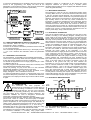
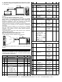
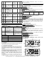
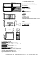
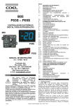
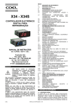
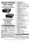
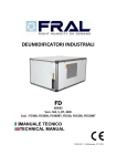
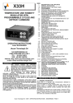
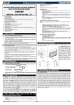
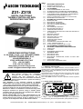
Z31- Z31S
DIGITAL ELECTRONIC
THERMO-CONTROLLER WITH
DEFROSTING FUNCTION
OPERATING INSTRUCTIONS
Vr. 02 (ENG) - 03/12 - cod.: ISTR-MZ31-ENG02
ASCON TECNOLOGIC S.r.l.
VIA INDIPENDENZA 56
27029 VIGEVANO (PV) ITALY
TEL.: +39 0381 69871
FAX: +39 0381 698730
http:\\www.ascontecnologic.com
e-mail: [email protected]
FOREWORD
INDEX
1
1.1
1.2
2
2.1
2.2
2.3
2.4
2.5
2.6
3
3.1
3.2
3.3
3.4
4
4.1
4.2
4.3
4.4
4.5
4.5.1
4.5.2
4.6
4.6.1
4.7
4.7.1
4.7.2
4.7.3
5
6
6.1
6.2
6.3
7
7.1
7.2
7.3
7.4
7.5
INSTRUMENT DESCRIPTION
GENERAL DESCRIPTION
FRONT PANEL DESCRIPTION
PROGRAMMING
FAST PROGRAMMING OF SET POINT
STANDARD MODE PARAMETERS PROGRAMMING
PARAMETER PROTECTION USING THE PASSWORD
CUSTOMIZED MODE PARAMETER PROGRAMMING
(PARAMETERS PROGRAMMING LEVEL)
RESET PARAMETERS TO DEFAULT VALUE/LEVEL
KEYBOARD LOCK FUNCTION
INFORMATION ON INSTALLATION AND USE
PERMITTED USE
MECHANICAL MOUNTING
ELECTRICAL CONNECTIONS
ELECTRICAL WIRING DIAGRAM
FUNCTIONS
ON / STAND-BY FUNCTION
MEASURING AND DISPLAY
TEMPERATURE CONTROL
COMPRESSOR PROTECTION FUNCTION AND DELAY
AT POWER-ON
DEFROST CONTROL
MANUAL DEFROST
DEFROST DISPLAY LOCK
ALARM FUNCTIONS
TEMPERATURE ALARMS
ACCESSORIES
PARAMETERS CONFIGURATION BY “A01”
“TVR Y” REMOTE DISPLAY
RS 485 SERIAL INTERFACE BY “TLCNV”
PROGRAMMABLE PARAMETERS TABLE
PROBLEMS , MAINTENANCE AND GUARANTEE
SIGNALLING
CLEANING
GUARANTEE AND REPAIRS
TECHNICAL DATA
ELECTRICAL DATA
MECHANICAL DATA
MECHANICAL DIMENSIONS, PANEL CUT-OUT AND
MOUNTING
FUNCTIONAL DATA
INSTRUMENT ORDERING CODE
1 - INSTRUMENT DESCRIPTION
1.1 - GENERAL DESCRIPTION
The model Z31 is a digital electronic thermocontroller that is
typically used in cooling applications that have temperature control
with ON/OFF mode and defrosting control with intervals time by
stopping compressor.
The instrument has one relay output and one input for PTC or NTC
temperature probes, in addition can be equipped with an internal
buzzer that is the sound system for alarms.
The model Z31S have the “S-touch” capacitive sensor keyboard
system.
This
manual
contains
the
information
necessary for the product to be installed
correctly and also instructions for its
maintenance and use; we therefore recommend
that the utmost attention is paid to the following
instructions and to save it.
1.2 - FRONT PANEL DESCRIPTION
This document is the exclusive property of ASCON
TECNOLOGIC which forbids any reproduction and divulgation
8
4
, even in part, of the document, unless expressly authorized.
ASCONT ECNOLOGIC reserves the right to make any formal or
6
3
functional changes at any moment and without any notice.
Whenever a failure or a malfunction of the device may cause
2
9
dangerous situations for persons, thing or animals, please
1
7
remember that the plant has to be equipped with additional
devices which will guarantee safety.
5
10
ASCON TECNOLOGIC and its legal representatives do not
assume any responsibility for any damage to people, things or
animals deriving from violation, wrong or improper use or in 1 - Key P : Used for setting the Set point (press and release) and
for programming the function parameters (hold pressed for 5 sec.)
any case not in compliance with the instrument’s features.
ASCON TECNOLOGIC - Z31- -OPERATING INSTRUCTIONS- Vr. 02 - 03/12 - ISTR-MZ31-ENG02 - PAG. 1
In programming mode is used to enter in parameters edit mode
and confirm the values.
In programming mode it can be used together with the UP key to
change the programming level of the parameters.
When the keyboard is locked it can be used together with the UP
(hold pressed for 5 sec.) key to unlock the keyboard.
2 - Key DOWN : In programming mode is used for decreasing the
values to be set and for selecting the parameters.
3 - Key UP/DEFROST : In normal mode can be used to start/stop
manual defrosting (hold pressed for 5 sec.).
In programming mode is used for increasing the values to be set
and for selecting the parameters.
In programming mode can be used togetherwith key P to change
parameters level.
Pressed together with the key P for 5 sec. allow the keyboard
unlock
4 - Key U : Used (press and release) for visualising the instrument
variables (measured temperatures etc.) .
In programming mode can be used to come back in normal mode
(hold for 2 sec.).
It can also be programmed via the parameter “t.UF”
In normal mode and if par. “t.UF” = 4 it can be used to turning on
and off (stand-by) the device (hold pressed for 1 sec.)
5 - Led SET : In normal mode it serves to indicate when a key is
pressed.
In programming mode indicates the programming level of the
parameters.
6 - Led OUT - COOL : Indicates the output status (compressor or
temperature control device) when the istrument is programmed for
cooling operation; on (on), off (off) or inhibited (flashing).
7 - Led OUT - HEAT : Indicates the output status (compressor or
temperature control device) when the istrument is programmed for
heating operation; on (on), off (off) or inhibited (flashing).
8 - Led DEFROST : Indicates defrosting in progress (on)
9 - Led ALARM : Indicates the alarm status (on), off (off) and
silenced (flashing)
10 - Led Stand-By: Indicate the Stand-by status.
To exit the programming mode, do not press any key for about 30
seconds, or keep the U key pressed for 2 sec. until it exits the
programming mode.
H o ld f o r
5 sec.
H o ld f o r
2 sec.
2.3 - PARAMETER PROTECTION USING THE PASSWORD
The instrument has a parameter protection function using a
password that can be personalised, through the “t.PP” parameter.
If one wishes to have this protection, set the password number
desired in the parameter “t.PP”.
When the protection is activate, press the P key to access the
parameters and keep it press for about 5 seconds, after which the
display will show “r.P” .
At this point press P, the display show “0”, using the UP and
DOWN keys, set the password number programmed and press
the key P.
If the password is correct, the display will visualise the code that
identifies the first parameter and it will be possible to program the
instrument in the same ways described in the previous section.
Protection using a password can be disabled by setting the
parameter “t.PP” = oF.
Hold for
5 sec.
2 - PROGRAMMING
.1 - FAST PROGRAMMING OF SET POINT
Press the key P then release it and the display will show “SP”
alternating with the set value.
To change it press the UP key to increase the value or DOWN to
decrease it.
These keys increase or decrease the value one digit at a time, but
if the button is pressed for more than one second the value
increase or decreases rapidly, and after two seconds pressed, the
speed increases even more to all the desired valued to be reached
rapidly.
When the desired value is set press the key P to exit from Set
Point programming mode.
Exiting the Set mode is achieved by pressing the P key or
automatically if no key is pressed for 10 seconds. After that time
the display returns to the normal function mode.
2.2 - STANDARD MODE PARAMETERS PROGRAMMING
To access the instrument’s function parameters when password
protection is disable, press the key P and keep it pressed for about
5 seconds, after which the display will visualised the code that
identifies the first parameter.
Using the UP and DOWN keys, the desired parameter can be
selected and pressing the P key, the display will alternately show
the parameter code and its setting that can be changed with the UP
and DOWN keys.
Once the desired value has been set, press the key P again: the
new value will be memorised and the display will show only the
code of the selected parameter.
Pressing the UP and DOWN keys, it is possible to select another
parameter and change it as described.
Hold for
2 sec.
Note: If the Password gets lost, just swith off and on the instrument
supply, push P key during the initial test and keeping the key
pressed for 5 seconds.
In this way it’s possible to have access to all the parameters, verify
and modify the par. “t.PP”.
2.4 - CUSTOMIZED MODE PARAMETER PROGRAMMING
(PARAMETERS PROGRAMMING LEVEL)
The password protection hides all the configuration parameters
behind a factory set password to avoid unwanted changes being
made to the programming of the controller.
To make a parameter accessible without having to enter the
password when “t.PP” password protection is activate follows this
procedure.
Enter the programming using the Password “t.PP” and select the
parameter which is desired to be accessible with no password
protection.
Once the parameter has been selected, if the SET led is blinking,
this means that the parameter is programmable by entering the
password (it’s then “protected”) if it’s instead on, this means the
parameter is programmable without password (not protected).
If you want to change the accessibility of the parameter push P
key, keep it pressed and press together also the key UP.
The led SET will change its state indicating the new access level of
the parameter (on = not protected; blinking = protected by
password).
ASCON TECNOLOGIC - Z31- -OPERATING INSTRUCTIONS- Vr. 02 - 03/12 - ISTR-MZ31-ENG02 - PAG. 2
In case some parameters are not protected, when one tries to have
access at the programming, the display will show all the
parameters not protected and the par. “r.P” (through which will be
possible to have access to the “protected” parameters.)
Hold for
5 sec.
Hold for
2 sec.
2.5 - RESET PARAMETERS TO DEFAULT VALUE/LEVEL
The instrument allows the reset of the parameters to values
programmed in factory as default.
To restore to the values of default the parameters set the value -48
to “r.P” password request.
Once confirmed the password with the key P the display it shows
"---" for 2 sec. therefore the instrument effects the parameters
reset..
Whenever a failure or a malfunction of the device may cause
dangerous situations for persons, thing or animals, please
remember that the plant has to be equipped with additional devices
which will guarantee safety.
3.2 - MECHANICAL MOUNTING
The instrument, in case 78 x 35 mm, is designed for flush-in panel
mounting. Make a hole 71 x 29 mm and insert the instrument, fixing
it with the provided special brackets. We recommend that the
gasket is mounted in order to obtain the front protection degree as
declared. Avoid placing the instrument in environments with very
high humidity levels or dirt that may create condensation or
introduction of conductive substances into the instrument. Ensure
adequate ventilation to the instrument and avoid installation in
containers that house devices which may overheat or which may
cause the instrument to function at a higher temperature than the
one permitted and declared. Connect the instrument as far away as
possible from sources of electromagnetic disturbances such as
motors, power relays, relays, solenoid valves, etc.
3.3 - ELECTRICAL CONNECTION
Carry out the electrical wiring by connecting only one wire to each
terminal, according to the following diagram, checking that the
power supply is the same as that indicated on the instrument and
that the load current absorption is no higher than the maximum
electricity current permitted. As the instrument is built-in equipment
with permanent connection inside housing, it is not equipped with
either switches or internal devices to protect against overload of
current: the installation will include an overload protection and a
two-phase circuit-breaker, placed as near as possible to the
instrument, and located in a position that can easily be reached by
the user and marked as instrument disconnecting device which
interrupts the power supply to the equipment. It is also
recommended that the supply of all the electrical circuits connected
to the instrument must be protect properly, using devices (ex.
fuses) proportionate to the circulating currents. It is strongly
recommended that cables with proper insulation, according to the
working voltages and temperatures, be used. Furthermore, the
input cable of the probe has to be kept separate from line voltage
wiring. If the input cable of the probe is screened, it has to be
connected to the ground with only one side. Whether the
instrument is F o G (12 / 24 V) supply version it’s recommended to
use an external transformer TCTR, or with equivalent features
(Class II insulation) , and to use only one transformer for each
instrument because there is no insulation between supply and
input. We recommend that a check should be made that the
parameters are those desired and that the application functions
correctly before connecting the outputs to the actuators so as to
avoid malfunctioning that may cause irregularities in the plant that
could cause damage to people, things or animals.
2.6 - KEYBOARD LOCK FUNCTION
On the instrument it’s possibile to lock completely the keyboard.
This function is particularly useful when the regulator is reachable
by the users and it’s desired to avoid any modification.
To activate the keyboard lock it’s enough program the par. “t.Lo”
to a different value to oF.
The value program to this parameter it is the time of inactivity of the
keys afterwhich the keyboard will be locked.
Insofar not pressing any key for the time "t.Lo" the instrument
automatically disable the normal functions of the keys.
When the keyboard is lock, if any of the key is pushed, on the
display will appear “Ln” to indicate the active lock.
To unlock the keyboard it’s enough to contemporarily push key P
and UP and keep them pushed for 5 sec., afterwhich the label “LF”
will appear on the display and all the keys functions will be availab3.4 - ELECTRICAL WIRING DIAGRAM
le again .
SPST-NO
3 - INFORMATION ON INSTALLATION AND USE
NO
C
INTERNAL
BUZZER
3.1 - PERMITTED USE
SPDT
The
instrument
has been
projected
and
NO NC C
INPUT
manufactured as a measuring and control device to
be used according to EN60730-1 for the altitudes
operation until 2000 ms. The use of the instrument
for applications not expressly permitted by the above mentioned
OUT
rule must adopt all the necessary protective measures. The
SUPPLY
61810
60730
instrument CANNOT be used in dangerous environments
EN
UL
EN
Out: 16 (9) A 10 (4) A 12 A Res.
(flammable or explosive) without adequate protection.
30 LRA
The instrument used with NTC 103AT11 probe (identifiable by the
5 FLA
PROBE
printed code “103AT-11” visible on the sensor part) is compliant
(12 A MAX for extr. conn. model)
with standard EN 13485 ("Thermometers for measuring the air and
product temperature for the transport,storage and distribution of
4 - FUNCTIONS
chilled, frozen, deep-frozen/quick-frozen food and ice cream”) with
the following classification: [EN13485 air, S, A, 2,- 50°C +90°C]
Remember that the end user must periodically checks and verify 4.1 - ON / STAND-BY FUNCTION
the thermometers in compliance with standard EN 13486.
The instrument, once powered up, can assume 2 different
The installer must ensure that EMC rules are respected, also after conditions:
the instrument installation, if necessary using proper filters.
Z31
1 2 3 4 5 6 7 8 9 10 11 12
ASCON TECNOLOGIC - Z31- -OPERATING INSTRUCTIONS- Vr. 02 - 03/12 - ISTR-MZ31-ENG02 - PAG. 3
- ON : means that the controller uses the control functions.
- STAND-BY : means that the controller does not use any control
function and the display is turned off except for the led Stand-by.
If there is no power, and then power returns, the system always
sets itself in the condition it was in before the black-out.
The ON/Stand-by function can be selected using the key U if the
parameter "t.UF" = 4.
Pressing the key U for at least 1 sec., it is possible to switch the
instrument from the ON status to Stand-by status and vice versa.
Programming instead “r.t1” to any value and “r.t2” = oF the output
in probe error condition will remain switched on.
Remember that the temperature regulation function can be
conditioned by the “Compressor Protections”, “Delay at power on”
and “Desfrost” functions.
4.4 - COMPRESSOR PROTECTION FUNCTION AND DELAY AT
POWER-ON
The function “Compressor Protection” aims to avoid close start ups
of the compressor controlled by the instrument in cooling
applications.
This function foresees 3 time controls on the switching on of the
output associated with the temperature regulation request.
The protection consists of preventing the output being switched on
during the times set in the parameters “P.P1”, “P.P2” and “P.P3”
and therefore that any activation occurs only after all the times has
finished.
First control (par. “P.P1” ) foresees a delay to the output activation
(switching-on delay).
4.2 - MEASURING AND DISPLAY
Via the parameter “i.SE” it is possible to select the type of probes
that one wishes to use and which can be: thermistores PTC
KTY81-121 (Pt) or NTC 103AT-2 (nt).
Via the parameter “i.uP”, it is possible to select the temperature
unit of measurement the desired measurement resolution (C0=°C /
1° ; C1=°C / 0.1° ; F0= °F / 1°; F1= °F / 0.1°).
The instrument allows the measuring to be calibrated, that can be
used for re-calibrating the instrument according to application
needs, through the parameters “i.C1”.
Using the parameter “i.Ft”, it is possible to set the time constant Temp.
for the software filter for measuring the input values to be able to
reduce the sensitivity to measurement disturbances (increasing the
r.d
SP
time).
The normal visualisation on the display is the measured
temperature but it is possible to visualise the highest and lowest
ON
ON
ON
time
peak measurement values; by quickly pressing and releasing key
Out off
U.
off
off
off
The display will alternately show:
“Lt” and the lowest peak temperature
“Ht” and the highest peak temperature
Second control (par. “P.P2” ) foresees an inhibition to the
“Pr1” and the instant measured temperature
activation of the output by a time delay that starts when the output
When the instrument is switched off, such values are always re-set. is turning off (delay after switching-off).
However, it is also possible to reset these values if the instrument
is switched on by using the DOWN key hold for 3 sec. during peak
Temp.
visualization.
The display will show “---” and peaks memory will be reset.
r.d
The exit of this visualisation mode occurs automatically 15 seconds
SP
after the last pressing on the key U.
Please remember that visualisation of the probe can be changed
ON
ON
ON
by the defrosting display lock function, by using the parameter
time
“d.dL” (see defrost function).
Out
off
off
off
4.3 - TEMPERATURE CONTROL
P.P2
P.P2
P.P2
The regulation of the instrument is ON/OFF and acts on the output
depending on the measuring of probe, of the Set Point “SP”, the Third control (par. “P.P3” ) foresees an inhibition to the activation
of the output "Out" by a time delay that starts when the output was
intervention differential “r.d” and the function mode “r.HC” .
Depending on the function mode programmed on the parameter turning on last time (delay between switching-on).
“r.HC” the differential is automatically considered by the regulator
with positive values for a Refrigeration control (“r.HC”=C) or with Temp.
negative values for a heating control (“r.HC”=H).
Temp.
Temp.
SP
r.d
r.d
SP
time
ON
ON
ON
r.d
SP
time
ON
ON
ON
ON
Out
ON
off
P.P3
ON
off
P.P3
time
off
P.P3
During the output inhibition the led OUT (Cool o Heat) blinking.
Out
Out
off
off
off
off
It is also possible to prevent activation of the output after the
instrument is turned on, for the time set in the parameter “P.od”.
r.HC=C
r.HC=H
During the power on delay phase, the display shows the indication
In the event of probe error, it is possible to set the instrument so od, alternating with the normal visualisation.
that that the output continues to work in cycles according to the All the functions are disabled by relative parameters = oF.
times programmed in the parameter “r.t1” (activation time) and
“r.t2” (deactivation time).
4.5 - DEFROST CONTROL
If an error occurs on the probe the instrument activates the output The automatic control of defrost, that is by stopping compressor,
for the time “r.t1”, then deactivates it for the time “r.t2” and so on occours by interval times
whilst the error remains.
The automatic defrost function is activate when at the parameter
Programming “r.t1” = oF the output in probe error condition will “d.di” is set the defrost interval time.
remain switched off.
The first defrost after swiching on can be set by par. “d.Sd”
ASCON TECNOLOGIC - Z31- -OPERATING INSTRUCTIONS- Vr. 02 - 03/12 - ISTR-MZ31-ENG02 - PAG. 4
This allows to perform the first defrost to a different interval from
"d.di." time.
If it is desired that to every instrument power on a defrost cycle is
realized program the par. "d.Sd" = oF.
Instead if is desired all defrost to the same interval program "d.Sd"
= "d.di."
Automatic defrost function is disable when “d.di” = oF.
The instrument provides to switch off the output for the time
“d.dE” each “d.di” time (of “d.Sd” in case of first defrost after
power on)
4.5.1 - MANUAL DEFROST
To start up a manual defrosting cycle, press the key UP/DEFROST
when it is not in programming mode and keep it pressed for about
5 seconds after which, if the conditions are correct, the led Defrost
will light up and the instrument will carry out a defrosting cycle.
To stop a defrosting cycle, press the key UP/DEFROST during the
defrost and keep it pressed for about 5 seconds.
4.5.2 - DEFROST DISPLAY LOCK
Through par. “d.dL” and “A.dA” it’s possible to define the display
behaviour during defrost.
The “d.dL” parameter pemits the display visualization lock on the
last temperature reading (“d.dL” = on) during all the defrost cycle
until, at the end of defrost, the temperature has not reached the
lock value or the value [”SP” + “r.d”] or is elapsed the time setted
on par. "A.dA".
Or it permits only the visualization of label “dEF” (“d.dL” = Lb)
during the defrost cycle and, after the defrost, of label “PdF” until,
at the end of defrost, the temperature has not reached the lock
value or the value [”SP” + “r.d”] or is elapsed the time setted on
par. "A.dA".
The display will otherwise (“d.dL”= oF) continue to visualize the
temperature measured by the probe during the defrost cycle.
the probe exceeds or goes below the respective maximum and
minimum alarm thresholds.
The alarm thresholds will be the same as those set on the
parameters “A.HA” and A.LA” if the alarms are absolute (“A.Ay”=1)
4.6 - ALARM FUNCTIONS
The alarm conditions of the instrument are:
- Probe errors “E1” , “-E1”
- temperature alarms “Hi” and “Lo”
The alarm functions of the instrument work on the led ALARM and
on the internal buzzer, if present and configured via the parameter
“o.bu”,
The possible selections of the parameter “o.bu” are:
= oF - Buzzer always disable
= 1 - Buzzer signal active alarms only
= 2 - Buzzer signal key pressed only (no alarm)
= 3 - Buzzer signal active alarms and key pressed
Any active alarm is shown on the instrument display with the
lighting up of the ALARM led, the silenced alarm status is shown by
the ALARM led flashing .
The buzzer (if “o.bu” = 1 or 3) is activated in alarm and can be
disabled (alarm silencing) manually by pressing any key of the
instrument .
4.6.1 - TEMPERATURE ALARMS
The temperature alarms work according to the probe
measurement, the type of alarm set in the parameter “A.Ay” the
alarm thresholds set in parameters “A.HA” (maximum alarm) and
“A.LA” (minimum alarm) and the relative differential “A.Ad”.
Through the parameter “A.Ay” it is possible to set the alarm
thresholds “A.HA” and “A.LA” which must be considered as
absolute (“A.Ay”=1) or relative to the Set Point (“A.Ay”=2).
Using some
parameters
it is also possible to delay the
enablement and the intervention of these alarms.
These parameters are:
“A.PA” - is the temperature alarm exclusion time on switching on
the instrument if the instrument is in alarm status when it is
switched on.
If the instrument is not in alarm status when it is switched on the
time "A.PA" it is not considered.
“A.dA” - is the temperature alarm exclusion time at the end of
defrosting
“A.At” - is the temperature alarm delay activation time
The temperature alarm is enabled at the end of exclusion time and
is enabled after the “A.At” time when the temperature measured by
4.7 - ACCESSORIES
The instrument is equipped with a connector that allows the
connection of some accessories described as follow.
4.7.1 - PARAMETERS CONFIGURATION BY “A01”
It is possible the transfer from and toward the instrument of the
functioning parameters through the device A01 with 5 poles
connector.
This device A01 it’s mainly useable for the serial programming of
the instruments which need to have the same parameters
configuration or to keep a copy of the programming of an
instrument and allow its rapid retransmission.
The same device can connect the instrument via USB to a PC and
through the proper configuration software tools "TECNOLOGIC
UniversalConf”, it’s possible to configure the operating parameters.
To use the device A01 it’s necessary that the device or instrument
are being supplied.
Tem p.
A .H A
A .A d
A .A d
A .L A
AL
o ff
ON
ON
Hi
Lo
o ff
tim e
o ff
oppure saranno i valori [”SP”+”A.HA”] e [”SP”+”A.LA”] se gli allarmi
sono relativi (“A.Ay”=2).
Tem p.
A .A d
A .H A
SP
A .L A
AL
A .A d
o ff
ON
ON
Hi
Lo
o ff
tim e
o ff
Gli allarmi di temperatura di massima e di minima possono essere
disabilitati impostando i relativi parametri "A.HA" e "A.LA" = oF.
SUPPLY
USB
USB
SUPPLY ADAPTER
12 VDC
AC SUPPLY
For additional info, please have a look at the A01 instruction
manual.
4.7.2 - “TVRY” REMOTE DISPLAY
To the instrument it is possible to connect the remote display TVR
Y through the special cable that can have a maximum length of 10
ASCON TECNOLOGIC - Z31- -OPERATING INSTRUCTIONS- Vr. 02 - 03/12 - ISTR-MZ31-ENG02 - PAG. 5
m. The device TVR Y, directly supplied by the instrument, it allows
to visualize the temperature measured by the probe Pr1 through a
2 ½ digit display.
SUPPLY
cable 10 m MAX.
TVR Y
For additional info, please have a look at the TVR Y instruction
manual.
4.7.3 - RS 485 SERIAL INTERFACE BY “TLCNV”
The instrument can be connected by a special cable to the TLCNV
device (mod. C - TTL/RS485 interface), by means of which it is
possible to connect the regulator with a net to which other
instruments (regulators of PLC) are connected, all depending
typically on a personal computer used as plant supervisor.
Using a personal computer it is possible to acquire all the function
information and to program all the instrument’s configuration
parameters.
The software protocol adopted for the instrument is a MODBUS
RTU type, widely used in several PLC and supervision programs
available on the market (Y and Z series protocol manual is
available on request).
If the instrument is used with TLCNV program by the parameter
"t.Ad" the station Address.
Set a different number for each station, from 1 to 255.
Note: The baud-rate are fixed at 9600 baud.
TLCNV interface is directly supplied by the instrument.
1
2
3
SUPPLY
cable
TLCNV
TTL
TLCNV
TX/RX
ON
7
8
9
4
5
6
GND B
A
RS 485
For additional info, please have a look at the TLCNV instruction
manual.
5 - PROGRAMMABLE PARAMETERS TABLE
Here below is a description of all the parameters available on the
instrument. Some of them may not be present because depend
on the model/type of instrument.
Par.
1
Description
Range
Def.
S. - parameters relative to Set Point
-99.9 ÷ HS
-50.0
S.LS Minimum Set Point
2
S.HS Maximum Set Point
99.9
LS ÷ HS
0.0
3
SP
4
i. -parameters relative to inputs
Pt / nt
i.SE Probes Type
5
6
7
Set Point
LS ÷ 999
i.uP Unit of measurement C0 / F0 / C1 /
and
resolution
F1
(decimal point)
C0 = °C with 1° res.
F0 = °F with 1° res.
C1 =°C with 0,1° res.
F1 = °F with 0,1° res.
oF ÷ 20.0
i.Ft Measurement filter
sec
-30.0 ÷ 30.0
i.C1 Probe Calibration
nt
C1
2.0
Note
°C/°F
r. - parameters relative to temperature control
Differential
0.0 ÷ 30.0
2.0
(Hysteresis)
°C/°F
9 r.t1 Output activation time oF/ 0.01 ÷ 9.59 oF
for probe error
(min.sec ) ÷
99.5
(min.sec.x10)
10 r.t2 Output
deactivation oF/ 0.01 ÷ 9.59 oF
time for probe error
(min.sec ) ÷
99.5
(min.sec.x10)
11 r.HC Output operating mode
H-C
C
H= Heating
C= Cooling
d. - parameters relative to defrosting control
12 d.di Defrosting interval
oF/ 0.01 ÷ 9.59 oF
(hrs.min. ) ÷
99.5
(hrs.min.x10)
13 d.Sd Delay first defrost after oF/ 0.01 ÷ 9.59 oF
power-on
(min.sec ) ÷
(oF = Defrost at
99.5
power-on)
(min.sec.x10)
14 d.dE Lenght of defrost cycle oF/ 0.01 ÷ 9.59 oF
(min.sec ) ÷
99.5
(min.sec.x10)
15 d.dL Defrost display Lock
oF - on - Lb
oF
oF= display free
on=
Lock
on
temperature
Pr1
before defrost
Lb= Lock on label
“dEF”
(during
defrosting) and “PdF”
(during
post-defrosting)
P. parameters relative to compressor protection and power
on delay
16 P.P1 Out delay at switch on oF/ 0.01 ÷ 9.59 oF
(min.sec ) ÷
99.5
(min.sec.x10)
17 P.P2 Out delay after switch oF/ 0.01 ÷ 9.59 oF
off
(min.sec ) ÷
99.5
(min.sec.x10)
18 P.P3 Out delay between oF/ 0.01 ÷ 9.59 oF
switching-on
(min.sec ) ÷
99.5
(min.sec.x10)
19 P.od Delay at power on
oF/ 0.01 ÷ 9.59 oF
(min.sec ) ÷
99.5
(min.sec.x10)
A. - parameters relative to alarms
20 A.Ay Temperature
alarms
1/2
1
Type:
(/ 3 / 4 / 5 / 6 /
1 = Absolute
7 / 8 = don’t
2 =Relative to Set
use)
21 A.HA High
temperature oF / -99.9 ÷
oF
Alarm threshold
999 °C/°F
22 A.LA Low
temperature oF / -99.9 ÷
oF
Alarm threshold
999 °C/°F
23 A.Ad Temperature
Alarms
0.0 ÷ 30.0
1.0
Differential
°C/°F
24 A.At Temperature Alarms
oF/ 0.01 ÷ 9.59 oF
delay
(min.sec ) ÷
99.5
(min.sec.x10)
8
r.d
0.0
ASCON TECNOLOGIC - Z31- -OPERATING INSTRUCTIONS- Vr. 02 - 03/12 - ISTR-MZ31-ENG02 - PAG. 6
6.1 - SIGNALLING
Error
Reason
The probe may be
E1
interrupted (E) or in
-E1
short circuit (-E), or may
measure a value outside
the range allowed
Internal
EEPROM
EPr
memory error
Fatal memory error
Err
Other Signalling:
Message
od
Ln
dEF
PdF
Hi
Lo
Action
Check
the
correct
connection of the probe
with the instrument and
check the probe works
correctly
Press key P
Replace the instrument
or ship to factory for
repair
Reason
Delay at power-on in progress
Keyboard lock
Defrosting in progress with “d.dL”=Lb
Post-defrosting in progress with “d.dL”=Lb
Maximum temperature alarm in progress
Minimum temperature alarm in progress
6.2 - CLEANING
We recommend cleaning of the instrument only with a slightly wet
cloth using water and not abrasive cleaners or solvents.
6.3 - GUARANTEE AND REPAIRS
The instrument is under warranty against manufacturing flaws or
faulty material, that are found within 12 months from delivery date.
The guarantee is limited to repairs or to the replacement of the
instrument.
The eventual opening of the housing, the violation of the instrument
or the improper use and installation of the product will bring about
the immediate withdrawal of the warranty’s effects.
In the event of a faulty instrument, either within the period of
warranty, or further to its expiry, please contact our sales
department to obtain authorisation for sending the instrument to
our company.
The faulty product must be shipped to ASCON TECNOLOGIC with
a detailed description of the faults found, without any fees or
7 - TECHNICAL DATA
7.1 - ELECTRICAL DATA
Power supply: 12 VAC/VDC, 12...24 VAC/VDC, 100...240 VAC +/10%
Frequency AC: 50/60 Hz
Power consumption: 3 VA approx.
Input/s: 1 input for temperature probes: PTC (KTY 81-121, 990 Ω
@ 25 °C) or NTC (103AT-2, 10KΩ @ 25 °C).
Output/s: 1 relay output SPST-NO or SPDT
EN 61810
EN 60730
UL 60730
Out - 16A - 1HP 16 (9) A
10 (4) A
12 A Res.,
250V, 1/2HP 125
30 LRA,
VAC
5 FLA
12 A Max. for extractable terminal block model
Electrical life for relay outputs: 100000 op. (EN60730)
Action type: type 1.B (EN 60730-1)
Overvoltage category: II
Protection class : Class II
Insulation: Reinforced insulation between the low voltage part
(supply H type and relay output) and front panel; Reinforced
insulation between the low voltage section (supply H type and relay
output) and the extra low voltage section (inputs); Reinforced
between supply and relay output; No insulation between supply F
or G type and inputs.
7.2 - MECHANICAL DATA
Housing: Self-extinguishing plastic, UL 94 V0
Heat and fire resistance category : D
Ball Pressure Test secondo EN60730: acessible parts 75 °C;
support live parts 125 °C
Dimensions: 78 x 35 mm, depth 64 mm
Weight: 120 g approx.
Mounting: Incorporated Flush in panel (thickness max. 12 mm) in
71 x 29 mm hole
Connections:
2,5 mm2 screw terminals block or 2,5 mm2
extractable screw terminals block for 0,2...2,5 mm2 / AWG 24...14
cables.
Degree of front panel protection : IP 65 (NEMA 3S) mounted in
panel with gasket
Pollution situation: 2
Operating temperature: 0 T 50 °C
Operating humidity: < 95 RH% without condensation
Storage temperature: -25 T +60 °C
7.3 - MECHANICAL DIMENSIONS, PANEL CUT-OUT AND
MOUNTING [mm]
78
35
6 - PROBLEMS, MAINTENANCE AND GUARANTEE
charge for ASCON TECNOLOGIC, except in the event of
alternative agreements.
78
35
25 A.PA Temperature
Alarms oF/ 0.01 ÷ 9.59 2.00
delay at power on
(hrs.min. ) ÷
99.5
(hrs.min.x10)
26 A.dA Temperature
Alarms oF/ 0.01 ÷ 9.59 1.00
delay
and
unlock (hrs.min. ) ÷
display delay after
99.5
defrost
(hrs.min.x10)
o. -parameters relative to buzzer
27 o.bu Buzzer function mode
oF / 1 / 2 / 3
3
oF = disable
1 = active alarms only
2 = key pressed only
3 = active alarms and
key pressed
t. - parameters relative to configuration of the keyboard
28 t.UF Function mode key U
oF / 4
oF
oF= No function
(1 / 2 / 3 =
4= Switch on/Switch
don’t use)
off (Stand-by)
29 t.Lo Keyboard lock function oF/ 0.01 ÷ 9.59 oF
delay
(min.sec ) ÷
30.0
(min.sec.x10)
30 t.PP Access Password to
oF ÷ 999
oF
parameter functions
31 t.AS MODBUS
Station
0 ÷ 255
1
address (for serial
communication)
ASCON TECNOLOGIC - Z31- -OPERATING INSTRUCTIONS- Vr. 02 - 03/12 - ISTR-MZ31-ENG02 - PAG. 7
7.5 - INSTRUMENT ORDERING CODE
min. 15 mm
Z31- (instrument with mechanical keyboard )
Z31S (instrument with Sensitive Touch keyboard )
29
71
min. 12 mm
a b c d e f g h ii jj
RECOMMENDED
PANEL CUTOUT
a : POWER SUPPLY
H = Supply 100..240 VAC
G = Supply 12..24 VAC/VDC
F = Supply 12 VAC/VDC
b : OUT
R = Out Relay SPST-NO 16A
S = Out Relay SPDT 16A
6
28
c : BUZZER
- = (No)
B = Buzzer
64
e : DISPLAY
- = Red
B = Blue
12,2
f, g, h : INTERNAL CODES
28
6
d : TERMINAL BLOCK
- = (Standard)
E = Extractable screw terminal block complete
N = Extractable terminal block without removable connectors
ii, jj : SPECIAL CODES
64
BRACKETS
MAX 12 mm
PANEL + GASKET
34
7.4 - FUNCTIONAL FEATURES
Temperature Control: ON/OFF mode
Defrost control: interval cycles by stopping compressor
Measurement range: NTC: -50...109 °C / -58...228 °F; PTC:
-50...150 °C / -58 ... 302 °F
Display resolution: 1 ° or 0,1° (range -99.9 ...99.9 °)
Overall accuracy: +/- (0,5 % fs + 1 digit)
Sampling rate: 130 ms.
Display: 3 Digit Red (or Blue as option) h 15,5 mm
Software class and structure : Class A
Compliance: Directive 2004/108/CE (EN55022: class B; EN610004-2: 8KV air, 4KV cont.; EN61000-4-3: 10V/m; EN61000-4-4: 2KV
supply and relay outputs, 1KV inputs; EN61000-4-5: supply 2KV
com. mode, 1 KV\ diff. mode; EN61000-4-6: 3V);
Directive 2006/95/CE (EN 60730-1, EN 60730-2-9).
Regulation 37/2005/CE (EN13485 air, S, A, 2,- 50°C +90°C with
probe NTC 103AT11).
ASCON TECNOLOGIC - Z31- -OPERATING INSTRUCTIONS- Vr. 02 - 03/12 - ISTR-MZ31-ENG02 - PAG. 8