1
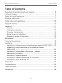
OWNER´S MANUAL
US
Permolock C
Locking System for
Power Wheelchair in Vehicle
How to contact Permobil
Head Office of the Permobil group
Permolock C
Locking System for
Power Wheelchair in Vehicle
Produced and published by Permobil AB, Sweden
Edition: 6, 2011-01
Order no.: 205014-US-0
4
Owner´s Manual Permolock C
Table of Contents
Table of Contents
Important information about user manual................................................... 6
Technical Support............................................................................................ 7
Spare Parts and Accessories........................................................................... 7
Warranty and Service....................................................................................... 7
Safety rules and regulations...................................................................... 8-9
Design & Function.......................................................................................... 10
Operation........................................................................................................
General .....................................................................................................
Locking the wheelchair .............................................................................
Releasing the wheelchair ..........................................................................
Manual release of wheelchair ...................................................................
Emergency release of wheelchair . ...........................................................
11
11
12
14
15
16
Maintenance . ................................................................................................ 17
Technical Specifications . .............................................................................. 18
Installation ...................................................................................................... 19
Installation of locking device on the wheelchair chassis (C400, C500)..... 20
Installation of control electronics on the wheelchair chassis
(C400, C500) ............................................................................................. 22
Installation of locking plate in the vehicle - General.................................. 24
Adjustment of lock plate . .......................................................................... 25
Installation of standard bracket ................................................................. 26
Installation of manual release lever in the vehicle .................................... 28
Installation of quick anchoring set . ........................................................... 30
Spare Parts .................................................................................................... 33
Troubleshooting ............................................................................................. 42
Crash test report ............................................................................................ 44
Accessories ................................................................................................... 48
5
Important Information about this Owner’s Manual
Owner´s Manual Permolock C
Important information about owner´s manual
Congratulations on choosing Permolock. Our goal is for you to continue to feel
satisfied with your choice of supplier and product.
Before you begin using your Permolock, it is important to read and understand the contents of these operating instructions and in particular the Safety
Instructions.
These operating instructions are primarily intended to acquaint you with the
Permolock’s functions and capabilities and to advise you how you can use them
in the best manner possible. They also contain important safety information and
describe some of the problems which might arise in use.
Always keep the safety manual in your vehicle as you may need to consult its
important information on use, safety and maintenance.
It is also possible to obtain information concerning our products from our home
page on the Internet. You can find us at www.permobil.com.
All information, pictures, illustrations and specifications are based upon the
product information that was available at the time that these operating instructions were printed. Pictures and illustrations that are found in these operating
instructions are representative examples and not intended to be exact depictions
of the various parts of the product.
We reserve the right to make changes to the product without prior notification.
Ordering of Documentation
If you are in need of another copy of the Owner’s Manual, it can be ordered
from Permobil, ask for item No. 205014-US-0.
6
Owner´s Manual Permolock C
Technical support, warranty, etc.
TECHNICAL SUPPORT
In the event of technical problems, you should contact your dealer or Permobil
Inc USA at 1-800-736-0925.
Always state the serial number when contacting Permobil to ensure that the
correct information is provided.
SPARE PARTS & ACCESSORIES
Spare parts and accessories must be ordered through your dealer.
SCRAPPING THE WHEELCHAIR
Contact Permobil Inc. for information about scrapping agreements in force.
WARRANTY
A warranty registration card is attached to each new Permolock C.
The Permobil Inc. Product Warranty Information sets forth the conditions of
the warranty.
Contact your dealer or Permobil Inc USA for information about the warranty
period for this product.
7
Safety rules and regulations
Owner´s Manual Permolock C
Safety rules and regulations
General
Permolock C is a locking device for fixing Permobil power wheelchairs in place
and is designed for use in vehicles.
It is important to read and follow the instructions and safety guidelines given in
this owner´s manual before starting to use your Permolock, as mistakes in use
could lead to risk of injury to user or passengers, or damage to the wheelchair,
the Permolock and the vehicle.
Any unauthorized alterations to Permolock C could lead to increased risk of
accident. Follow closely the recommendations in the section on Operation, in
order to avoid risk of accident during use.
Warning labels
Throughout this manual the following symbol will be used to note items that have
significant importance to safety concerns.
m CAUTION
Please use caution where this symbol appears.
m
WARNING
Please use extreme caution where this warning symbol appears.Failure to observe warnings can
lead to personal injury and property damage, including damage to the wheelchair.
m
WARNING
If the Permolock is involved in an accident of any kind, the locking base, plunger and manual
release mechanism must be replaced. An accident can cause damage to the Permolock that
you cannot see.
m
WARNING
Do not modify the Permolock or use any accessories or parts not specified by Permobil.
8
Safety rules and regulations
Owner´s Manual Permolock C
m NOTE
Permobil is not responsible for personal injuries or property damage resulting from any person’s
failure to follow the warnings and instructions in this manual. Permobil is not responsible for injuries
or damage resulting from failure to exercise good judgment.
Once the Permolock C has been installed by a National Mobility Equipment Dealers Association
(NMEDA) Certified Dealer; any Permobil, Inc. Certified Dealer can service the Permolock C, as
long as the part that is being serviced does not involve removing or replacing the locking base
plate. If the locking base plate must be removed or replaced, a NMEDA Certified dealer should
perform the service/repair.
m
WARNING
To be checked before first use
Before using your wheelchair with Permolock C, you must check that the chair has been suitably
adjusted. Contact your supplier for information. Failure to properly install and use the Permolock
increases the risk of serious injury or death in a sudden stop or crash.
To be checked before setting off
Check that the lamp on the control button in the vehicle is shining green after locking has been
activated. If the light is not shining green, the wheelchair is not secure in the lock.
Maintenance and service
Carry out only the service and maintenance activities noted in this user manual. All other servicing,
alterations and changes to the vital systems of Permolock C and its accessories must be carried
out by a NMEDA certified Technician or person with sufficient knowledge to give a competent
result. In case of doubt always contact a competent servicing engineer or Permobil.
Use only spare parts or accessories approved or recommended by Permobil. All other use could
lead to changes which might impair the function and safety of the lock. It could also lead to the
guarantee on your Permolock C becoming invalid.
m
CAUTION
Recycling of electronic parts
Obsolete electronics should be disposed of responsibly in accordance with local recycling regulations.
EMC requirements
The electronics in the vehicle locking system may be affected by external electromagnetic fields
(e.g. from cellphones). Likewise the electronics in the locking system themselves may emit electromagnetic fields which could affect the surrounding area.
The threshold values for Electro-Magnetic Compatibility (EMC) relating to electric wheelchairs and
their accessories are laid down in harmonized standards under EC Directive 93/42/EEC Medical
Devices.
Permolock C meets these threshold values.
9
Owner´s Manual Permolock C
Design and function
Design & Function
General
Permolock C consist of two elements. One is a locking device mounted to the
wheelchair chassis and operated by a control button on the front edge of the
armrest. The second element, a locking plate, is mounted in the vehicle. This is
operated by a control button mounted in the vehicle.
1
2
3
4
1.
2.
3.
4.
5.
Locking device
Locking mechanism
Locking plate
Handle for emergency release
Handle for manual release
10
5
Owner´s Manual Permolock C
Operation
Operation
General
Permolock C is designed to secure an occupied wheelchair in a moving vehicle
and is suitable for either the driver or passengers.
Permolock C must only be used together with Permobil electric wheelchairs
approved for this purpose and with the chair base available as an accessory.
It may be necessary to have your wheelchair adjusted to work with Permolock.
A test locking must always be performed in the presence of the person fitting
the lock.
The installation of the Permolock C must be performed by a National Mobility
Equipment Dealers Association (NMEDA) Certified Dealer.
11
Owner´s Manual Permolock C
Operation
Operation
Locking the wheelchair
Permolock C consists of two elements.
One is a locking device mounted on the
wheelchair chassis and operated by a
control button on the front edge of the
armrest, see photo.
The second element, a locking plate,
is mounted in the vehicle. This is operated by a similar control button mounted in the vehicle. The position of the
control button may vary depending on
the vehicle and the user’s needs. The
photo on page 13 shows an example
of a commonly used position.
1. To prepare the wheelchair for locking, keep the button on the front
edge of the armrest pressed in for
three seconds - the locking device
underneath the wheelchair will
extend.
The locking device will remain in
extended position for 40 seconds.
During this period the control button lamp will show an orange color,
indicating that the wheelchair is
ready for locking in the locking
plate. If you do not manage to lock
the wheelchair during this time,
repeat the above procedure.
The locking device’s control button is
mounted on the wheelchair armrest.
Control button lamp.
12
Owner´s Manual Permolock C
Operation
Locking the wheelchair
2. Move the wheelchair straight in
over the locking plate so the locking device on the chair engages
with the locking plate mechanism
and comes to a mechanical stop.
The locking plate control button,
which is mounted in the vehicle,
will shine green. This indicates that
the wheelchair has been correctly
locked.
m
Example of position of control button
in the vehicle.
WARNING
Make sure the lamp on the control button at the front edge of the armrest lights up orange as you
drive in over the locking plate.
Check that the lamp on the control button in the vehicle is shining green after locking has been
activated. If the lamp is not green, your wheelchair is not secured in the locking plate and could come
loose in the event of a collision.
3. After you are correctly locked in the Permolock, fasten your vehicle mounted
seat belt.
Move the wheelchair in over Permolock C.
13
Owner´s Manual Permolock C
Operation
Releasing the wheelchair
Wheelchair release is performed electrically and is activated with the control
button mounted in the vehicle. The
position of the control button may
vary, depending on the vehicle and the
user’s needs. The photo to the right is
an example of a commonly used position.
1. To open the locking mechanism on the locking plate, keep the locking plate control button pressed in for three seconds if the vehicle is turned on at the ignition, otherwise for one second. The locking plate mecha- nism will open and the wheelchair can now be backed out of the lock.
Example of position of
control button in the vehicle.
When the wheelchair is being
backed out of the locking plate, the control button’s green lamp will go out.
After 15 seconds, the lock will return
to its original position and is then
ready for relocking again.
Backing the wheelchair out of Permolock C.
14
Owner´s Manual Permolock C
Operation
Manual release of wheelchair
If the vehicle battery is discharged,
it will still be possible to release the
wheelchair manually. This is done with
a manual release lever, the position of
which in the vehicle may vary depending on type of vehicle and the user’s
needs.
Locked position
1. To open the locking plate
mechanism manually, move the lever to
its open position, see photo. The
locking plate mechanism will open
and the wheelchair can now be
backed out of the lock.
m NOTE
In the event of manual release on a steep
upwards gradient, the wheelchair may simultaneously be “driven” forward to ease release.
Open position
2. As the wheelchair is being backed
out of the locking plate, reset the
locking mechanism to locked position by moving the lever back to
its original position.The lock is then
ready for relocking again.
m
Manual release of wheelchair
CAUTION
Always reset the locking mechanism to the
locked position after backing the wheelchair off
the locking plate. If you do not reset the lock, it
will not be ready for relocking.
Backing the wheelchair out of Permolock C.
15
Owner´s Manual Permolock C
Operation
Emergency release of wheelchair
In an emergency, the locking mechanism can be opened manually with the
emergency handle on the front edge of
the locking plate.
1. Remove the emergency handle from
its bracket, see photo.
2. Mount the emergency handle on the
locking mechanism, see photo.
Handle for manual
release in emergency situation.
3. Slide the emergency handle sideways while backing the wheelchair
out of the lock, see photo.
m
WARNING
The user will need assistance in operating the
manual emergency release, because in most
cases the user will not be able to reach it.
Mount the handle and
press to the left.
Backing the wheelchair out of Permolock C.
16
Owner´s Manual Permolock C
Maintenance & Technical specifications
Maintenance
Cleaning
The following is general advice recommended by Permobil. For severe soiling or
damage to surface finish, contact Permobil for information.
For normal cleaning proceed carefully with a soft cloth/sponge, hot water and a
mild detergent. Wipe down carefully with a cloth and water, and dry off.
m
VARNING
Never hose the lock down as the electronics may be damaged.
Check the diameter of the locking device regularly using the accompanying inspection wrench.
If the locking device fits within the wrench opening, then the locking device is worn and therefore
must be replaced.
Regular maintenance
- Sparingly grease the contact surfaces of
the locking
mechanism
Redguard,
remove any
device and the locking plate
on a regular basis (Lubetec
Art.no.1190). Use a file to
sharp edges.
- Check the diameter of the locking device
regularly using the accompanying inspection wrench. If the locking device fits within
the wrench opening, then the locking device
is worn and therefore must be replaced.
17
Important!
Check the diameter of the
locking device regularly.
Owner´s Manual Permolock C
Technical specification
Technical specifications
DATA
General
Name................................................................................
Dimensions and weight
Length..............................................................................
Width................................................................................
Height...............................................................................
Weight..............................................................................
Permolock C
20” (500 mm.)
17” (425 mm.)
3 1/4 (83 mm.)
29 Ibs.
Electrical system
Voltage Permolock........................................................... 12V / Car
Voltage Locking device.................................................... 24V / Wheelchair
18
INSTALLATION
Permolock C
Locking System for
Power Wheelchair in Vehicle
Owner´s Manual Permolock C
Installation
Installation
Installation of locking device on the wheelchair chassis
(C400, C500)
Read through the instructions before starting installation.
1. Remove the wheelchair chassis
cover, the right-hand battery and, on
Pilot+ models, the main fuse. For a
detailed description, see the appropriate chassis service manual.
2. Lift/angle the wheelchair so that the
underside of the chassis can be
accessed.
m
WARNING
The wheelchair is heavy, therefore ensure it
remains stable after the chassis has been lifted/
angled or it could fall and cause personal injury
or property damage.
Tap loose the plate covering the channel.
3. Using a hammer and tool, tap loose
the plate covering the channel intended for the locking device, see photo.
With a long tool or similar through
the chassis channel, the plate can be
tapped loose from the inside of the
chassis and in this way there is no risk
of the plate jamming in the channel.
Use a file to remove any sharp
edges around the channel opening.
m CAUTION
Grease the sliding surfaces of the locking
device (Mobil 1 Synthetic grease, Product
Code: 53201-0), before mounting.
Check before installation that the channel in the
chassis is free of electroplating residue and dirt
that could cause the locking device to become
stiff and difficult to operate. The lock pin could
get stuck up or down.
20
Installation of locking device.
Owner´s Manual Permolock C
Installation
4. Install the locking device from underneath the chassis. Use the accompanying tool to keep the locking
device in place, see photo.
5. Install spring, washer and screw
from the upper side of the chassis.
A long screwdriver or similar can be
used to guide the parts into place.
Tighten the screw, applying pressure to the underside of the chassis
using the accompanying tool.
Tightening torque: 43 ft-Ibs (59Nm).
m
Fit the solenoid in the chassis with the flat
surface of the upper part facing backwards.
CAUTION
Make sure the locking device fits easily into the
chassis channel, otherwise it will not install
properly.
6. Set the wheelchair back on all four
wheels.
7. Install the solenoid in the chassis.
Fit the solenoid in the chassis with
the flat surface of the upper part
facing backwards, see photo.
8. Chassis with Pilot+
Fit the washer supplied.
Installation of solenoid
on chassis with Pilot+.
Install the main fuse along with the
plate supplied. Fit using the longer
screws supplied (M5x40) - see photo.
m
CAUTION
Note the direction in which the fuse is installed.
The ON/OFF position must match the sticker
supplied for the chassis cover.
Chassis with VSI
Fit the washer supplied.
Fit the washer using the shorter screws supplied (M5x10), see
photo.
Installation of solenoid
on chassis with VSI.
21
Owner´s Manual Permolock C
Installation
Installation of control electronics on the wheelchair chassis
(C400, C500)
Read through the instructions before starting installation.
1. Install the control electronics for the
locking device in the wheelchair
chassis. Guide the electronics box
down on the right side of the locking device, see photo.
2. Screw down the box with the two
M4 screws supplied, see photo.
3. Using the control button bracket,
mark out attachment holes for the
bracket at the front edge of the armrest. Drill Ø 3mm holes. Drill also a
Ø 6mm hole for the cable ties for
the cabling inside the armrest, see
photo.
Install the control electronics box using
the M4 screws supplied.
4. Fit the locking device control button
at the front edge of the armrest using
the M3 screws supplied, see photo.
Drill holes for the cable button
bracket and the cable ties.
5. Fit the cabling for the control button
using cable ties inside the armrest,
see photo.
22
Fit the control button cabling and
connection contact
with the cable ties in the armrest.
Owner´s Manual Permolock C
Installation
6. Chassis with Pilot+
Connect the control electronics to the +24V outlet on the SLS card. If the wheelchair seat is equipped with an electric actuator, remove the contact for this
from the SLS card and instead connect it to the +24V outlet on the
cabling for the control electronics, see photo. For more information on the SLS
card, see the current chassis service manual.
Pilot+
Connect to
+24V outlet.
SLS card.
Locking device
control electronics
+24V outlet.
To seat actuator.
VSI
Connect to
the cabling
below.
Pilot+
Connect the control electronics to the +24V outlet on the SLS card. If the wheelchair seat is equipped with an electric actuator, connect this to the new +24V
outlet.
VSI: Connect the control electronics cables to the cables below.
Chassis with VSI
Using the cabling supplied, connect the control electronics direct to the wheelchair batteries.
Fuse
10A.
Connect to
cabling
above.
+24V battery.
Red
GND. Battery.
Black
Cabling for connection to VSI in chassis.
23
Owner´s Manual Permolock C
Installation
Installation of locking plate in the vehicle - General
Read through the instructions before starting installation.
m CAUTION
To ensure that the wheelchair locking device ends in the correct position for locking, it is important
that the locking plate is mounted correctly in relation to the wheelchair wheels. When mounting on a
sloping surface, the locking plate may be raised using spacers to ensure satisfactory engagement
and locking. See the examples below. Spacers for use when installing on a sloping surface are
available as accessories, see page 17.
When installing the locking plate on a sloping surface, alternative mounting of the rubber rollers on
the plate may be necessary, see page 25.
The chair lock must be anchored in a manner that is safe for the type of vehicle involved and which
conforms to the relevant countryís regulations.
The chair lock must be anchored in such a way that no other components are damaged and the
strength of the vehicle floor is not impaired.
Vehicle floor
Locking plate
Spacer
m CAUTION
Installation with sloping surface
In order to ensure proper installation:
1. Check after installation that the chair lock is not warped and that the lock functions correctly.
2. The lock must be tested with the user sitting in the wheelchair.
3. Check that the wheelchair shock absorbers are set for the right user weight, see the relevant
chassis service manual.
4. Also check that the air pressure in the wheelchair tires is correct, see the relevant chassis
user manual.
24
Owner´s Manual Permolock C
Installation
Adjustment of locking plate
Rubber rollers
The rubber rollers on the rear edge of
the locking plate can be installed in two
different positions, see photo.
1
Position 1: Standard, rubber rollers
mounted in the rear holes (1), see
photo.
Position 2: Alternative mounting where
the plate is fitted on a sloping surface,
and the rubber rollers are mounted in
the front holes (2), see photo.
2
The position of the rear rubber rollers must be altered where the plate is
installed on a sloping surface.
Rubber stops
The rubber stops at the front edge of
the locking plate can be fitted with or
without spacers, depending on the specific wheelchair chassis.
1
2
Permobil C400: Fit the rubber stop
(1) with a spacer (2), screw it firmly in
place using a nut (4) and washer (3),
see photo.
3
4
Permobil C500: Fit the rubber stop
(1) without a spacer, screw it firmly in
place using a nut (4) and washer (3),
see photo.
The fitting of the rubber stops should be
adjusted to suit the specific wheelchair.
25
Owner´s Manual Permolock C
Installation
Installation of locking plate
with standard bracket
Read through the instructions before
starting installation.
1. Install the four brackets in the
standard position (the central hole
configuration) on the lock plate, see photo.
2. Position the lock plate correctly in the vehicle.
m
One of the lock plates four brackets
installed in the standard position.
WARNING
The locking plate must always be installed with
its front edge facing the direction of travel, see
photo on page 27.
3. Using the hole between the bracket
bolts as a guide, drill 4 x Ø10 mm
holes through the vehicle floor, see
photo.
4. Remove the locking plate and dismount the four brackets.
5. Install the four brackets in the
vehicle
using
countersunk
screws of min. M10 8.8 through the
holes previously drilled.
Use the hole between the
bolts of the brackets as a guide.
The screws must go right through
and have a suitable body washer
and nut on the underside.
m
WARNING
These screws are not supplied with Permolock
C. Screws must be M10 8.8 grade and of a suitable length for the floor thickness of the vehicle.
Incorrect fastener use could cause the Permolock
to break free in a collision and cause serious personal injury or property damage.
Install the four brackets in the vehicle.
26
Owner´s Manual Permolock C
Installation
6. Position the locking plate correctly
on top of the mounting plates. It
can be installed in three different
positions, ”Standard” or + or - 30
mm. The front hole is not used with
the standard bracket.
7. Mount the plate in the desired position with the supplied screws and
washers.
Tightening torque:18 ft-Ibs (24,5Nm)
8. Connect the cabling from the locking plate to the vehicle’s electrical
system. Connect the red cable to the
fused +12V (10A).
Red cable
Black cable
Locking plate mounted in standard position. The hole indicated is not used when
installing with the standard bracket.
- +12V. (10A)
- Earth
Orange cable - 12V switched power, key on engine running.
FORWARD
Direction of
travel
Direction of
travel
BACK
The lock plate must always be fitted with its front edge in the vehicle´s direction of travel.
27
Owner´s Manual Permolock C
Installation
Installation of manual release lever in a vehicle
Read through the instructions before starting installation.
The manual release lever must be
installed so that the user can easily
operate it when necessary. The lever
is intended for cases where the vehicle
electrical system is not functioning
optimally.
Remove the plastic cover from the
lever by manually unclipping the sides
of the cover at the bottom edge,see
photo.
Preliminary adjustment
The release mechanism can be turned
to suit installation on either the right or
left side.
m
The plastic cover can be unclipped
by hand.
WARNING
The handle must always be mounted so that the
stop screw (7) is in front of the release handle
(1), see page 29. This will prevent the release
control from inadvertently releasing.
1
1. Move the stop screws between positions 2 and 7, see photo.
2. Remove the cable bracket (5) from
the release arm (10) see photo.
3. Turn the release arm (10) and move
it between fixing points 4 and 9.
4. Remove the cable bracket (5) from
the release arm (10) see photo.
Installation
1. Install the release controls using
three M4 screws with countersunk
heads through holes 3, 6 and 8, see
photo.
2
7
3
8
4
9
5
10
6
Manual release handle.
2. Refit the plastic cover.
28
Owner´s Manual Permolock C
Installation
= Position of the stop screws
x
Ma
45°
ax
M
90
°
Correct
installation
Direction of travel
Prohibited
installation
Installation of release lever.
29
Owner´s Manual Permolock C
Installation
Installation of quick anchoring set Order no:1820549
List of parts that should be in the set
1.
2.
3.
4.
4
4
4
4
pcs.
pcs.
pcs.
pcs.
Lock nuts M10 fzb
Washer BRB 10.5x20x2 fzb
Keyhole bolt
Keyhole plates
5. 1 pc.
6. 1 pc.
7. 2 pcs.
Tool clamp
Allen key 8 mm
Installation spacers
Read through the instructions before starting installation.
7
1
2
3
4
5
6
Quick anchoring set.
30
Owner´s Manual Permolock C
Installation
1. Check that the cc distance between
the keyholes is L= 350 mm. and
B= 368 mm. Mark the hole configuration of the plates on the vehicle
floor, see photo.
350 mm.
FORWARDS
m WARNING
The locking plate must always be installed with
its front edge facing the direction of travel, see
photo on page 27.
368 mm.
Mark the hole configuration
of the plates on the vehicle floor.
The plates must be fitted with the narrow end
of the hole in the direction of travel or the
Permolock could come loose in a collision.
mm.
Ø60
mm.
Ø6.5
2. Drill a Ø6.5mm. hole through the
inner and outer floor of the vehicle,
using the keyhole plate as a template.
3. Mark the centre of the keyhole’s
large radius. Using a hole-making
tool, drill a Ø60mm hole through
the inner floor of the vehicle, see
photo.
oor
r fl
Oute
4. Screw the keyhole plates firmly in
place using ISO 10642 M6 10.9
Fe/Zn 5 C1 screws of an appropriate length for the thickness of the
floor.
or
r flo
Inne
The large Ø60 mm hole should be
drilled in the inner floor of the vehicle
only.
The screws must go right through
and have a suitable body washer
and nut on the underside.
5. Fix
the
self-adhesive
tool
clamp to the locking plate, see
photo.
Fix the self-adhesive
tool clamp.
31
Owner´s Manual Permolock C
Installation
6. Screw the keyhole bolts in place
in the hole configuration that best
suits the user (choice of 4).
Use the supplied 10.5x20x2 shim
and locknut M10.
m CAUTION
It is important that the lock plate be fitted in
a straight line in relation to the wheelchair
wheels. If necessary, fit spacers between the
keyhole bolts and the lock plate, see page 24.
Screw the keyhole bolts in place using
the hole configuration that best suits the
user (choice of 4).
The chair lock must be anchored in a manner
that is safe for the type of vehicle involved
and which conforms to the relevant country´s
regulations or the Permolock might not perform as certified in the crash tests.
Locking screw
Hole configuration. 1
Hole configuration. 2
Hole configuration. 3
Hole configuration. 4
Fit the keyhole bolts in any of the four hole
configurations. Lock using the locking
screws after installation in the vehicle.
7. Secure the screws ISO 4762
M10x35 12.9 Fe/Zn 8 C4 in the
threaded holes immediately in
front of the rear keyhole bolts, see
photo.
8. Push the lock plate into the keyhole plates and lock by screwing
the two lock screws firmly in place,
see photo.
Permolock C installed with
quick anchoring set.
32
SPARE PARTS
Permolock C
Locking System for
Power Wheelchair in Vehicle
Owner´s Manual Permolock C
Spare Parts
4
1
3
2 - 17
10
15
8
13
9
7
5
14
13
6
11
12
16
17
2
14
13
12
34
Owner´s Manual Permolock C
POS QTY
PART NO.
Spare Parts
DESCRIPTION
01
02
03
1
314036-99-0
1
1
MAN.CONTROL
HOLDER
HANDLE
04
05
06
1
612837-02-0
1
602367-99-0
1
PLASTIC KNOB 4x13
SCREW ISO 7380 M6x25 10.9 Fe/Zn 5 C1
BUSH
07
08
09
1
1
1
600238-99-0
600227-99-0
601296-99-0
WASHER ISO 7089 6 200 HV Fe/Zn 5 C1
LOCKINGNUT ISO 7040 M6 Fe/Zn 5 C1
WASHER ISO 7089 4 200 HV Fe/Zn 5 C1
10
11
12
1
601282-99-0
1
3
SCREW ISO 4762 M4x5 8.8 Fe/Zn 5 C1
HOOK
COTTER
13
14
15
6
600842-99-0
WASHER 5 Fe/Zn 5 C1 (SRB 5.3x12x1)
3
1
603083-99-0
313997-00-0
SHACKLE
COVER
16
17
1
1
314526-99-0
612885-99-0
WIRE
SPRING DF 0,5x8x60
35
Owner´s Manual Permolock C
Spare Parts
10
9
1
2 - 21
8
14
2
13
17
7
12
11
6
19
5
20
3
4-7
15
18
16 - 17
21
4
36
16
Owner´s Manual Permolock C
POS QTY
PART NO.
DESCRIPTION
01
02
03
1
1
1
04
05
06
1
1
1
VEHICLE LOCK
SPRING TF 1,6x20x77,1
WASHER
07
08
09
1
612360-99-0
1
2
612882-99-0
SCREW ISO 10642 M10x25 10.9 Fe/Zn 8 C1 SPACER
SCREW ISO 4017 M5x40 8.8 Fe/Zn 5 C1
10
11
12
2
1
1
601161-99-0
313631-99-0
306971-99-0
SCREW ISO 4017 M5x10 8.8 Fe/Zn 5 C1
PCB PERMOLOCK C
STICKER
13
14
15
2
1
1
601381-99-0
1820542
311365-00-0
SCREW ISO 7380 M4x8 10.9 Fe/Zn 5 C1
CABLE KIT 24V P+/VSI
CABLE KIT Release button
1
1
1
1820526
1
CABLE
CABLE
STICKER KIT
BRACKET
2
1
SCREW ISO 7045 M3x6 4.8 Z Fe/Zn 5 C1
TOOL
16
17
18
19
20
21
313344-99-0
612875-99-0
1820529
Spare Parts
602065-99-0
314541-99-0
LOCK
SOLENOID RE-5 24V 29,5
PLUNGE KIT
37
L.C DIN 267-28
Owner´s Manual Permolock C
Spare Parts
15
13
1
14 - 15
2 - 53
17
14
50
26
10
9
18 - 21
11 12
16 21
19
20
23
18
22
25
4
24
8
5
7
35
3
29
36
34
28
6
27
2
31
30
33
37
32
40
41
49
38
39
52
53
51
43
47
48 - 53
46
48
42
38
42 - 46
44 45
Owner´s Manual Permolock C
POS QTY
PART NO.
Spare Parts
DESCRIPTION
01
313072-28-0
02
1
03
2
313047-00-0
VEHICLE LOCK
PLATE
SLIDE BAR
04
05
06
10
8
4
600208-99-0
612913-99-0
612840-99-0
SCREW DIN 7991 M4x10 10.9 Fe/Zn 5 C1
WHEEL Ø50x19
CYLINDRIC BOLT ISO 2341B 6x60 Fe/Zn
07
08
09
4
4
2
600238-99-0
612839-99-0
612721-99-0
WASHER ISO 7089 6 200 HV Fe/Zn 5 C1 (6,4x12x1,6)
HITCH PIN CLIP Ø1,2 Stright
RUBBER BLOCK Ø30x15 M8x20 type D Nr 60SH
10
C-400
11
12
2
SPACER
2
2
WASHER ISO 7089 8 200 HV Fe/Zn 5 C1 (8,4x16x1,6)
LOCKING NUT ISO 7040 M8 6 Fe/Zn 5 C1
13
14
15
1
1820526
1
2
STICKER KIT
STICKER GUIDE LINE
STICKER EMERGENCY RELEASE
16
17
18
1
1
1820527
1
STICKER CHASSIS NO
EMERGENCY HANDLE KIT
SPRING CLIP Ø3,2 (13-15) fzb
19
20
21
1
600772-99-0
1
1
SCREW ISO 7049 ST 2,9x9,5 C Z Fe/Zn 5 C1
EMERGENCY HANDLE
RUBBER RING Ø11,1x1,6 NBR70
22
23
24
1
2
600772-99-0
4
PLATE BRACKET
SCREW ISO 7049 ST 2,9x9,5 C Z Fe/Zn 5 C1
PLATE
25
26
27
8
612888-99-0
8
600203-99-0
1
LOCK WASHER 8,7x13,5x2,5 NORDLOCK
SCREW ISO 4762 M8x20 8.8 Fe/Zn 5 C1
RUBBER BLOCK Ø20x12 M6x10 type D NBR60SH
28
29
30
1
600227-99-0
1
1
LOCKING NUT ISO 7040 M6 6 Fe/Zn 5 C1
WASHER LOW FRICTION
HOOK
31
32
33
1
1
1
612831-99-0
WASHER LOW FRICTION
WASHER
LOCKING NUT DIN 6925 M10 6 Fe/Zn 8 C1
34
35
1
1
612692-99-0
612898-99-0
SPRING DF 1,5x15x60
SCREW ISO 4017 M5x10 Fe/Zn 5 C1 36
1
601935-99-0
WASHER SRKB5,5x22x1,5 fzb
37
38
39
1
2
600239-99-0
2
600228-99-0
267-28
600239-99-0
600228-99-0
Only
SHAFT
WASHER ISO 7089 8 200 HV Fe/Zn 5 C1 (8,4x16x1,6)
LOCKING NUT ISO 7040 M8 6 Fe/Zn 5 C1
39
L.C. DIN
Owner´s Manual Permolock C
Spare Parts
15
13
1
14 - 15
2 - 53
17
14
50
26
10
9
18 - 21
11 12
16 21
19
20
23
18
22
25
4
24
8
5
7
35
3
29
36
34
28
6
27
2
31
30
33
37
32
40
41
49
38
39
52
53
51
43
47
48 - 53
46
48
42
40
42 - 46
44 45
Owner´s Manual Permolock C
POS QTY
PART NO.
Spare Parts
DESCRIPTION
40
41
42
1
612722-99-0
1
313631-99-0
1
ACTUATOR LAS-1 25mm
ELECTRONICS
PCB ACTU
43
44
45
4
1
1
CIRCUIT BOARD SUPPORT Ø4x4/Ø3
CONSOLE
STICKER SERIAL NO
46
47
48
2
601381-99-0
1
1820545
1
SCREW ISO 7380 M4x8 10.9 Fe/Zn 5 C1
CABLE KIT lock indicator
CABLE
49
50
51
1
2
1
CABLE
SCREW M2,3x14 4.8 H Fe/Zn 3 C1
MICROSWITCH WASHER 52
53
2
2
WASHER DIN 6798A 2,5x5x0,4 Fe/Zn 5 C1
NUT DIN 934 M2,3 8 Fe/Zn 3 C1
41
Owner´s Manual Permolock C
Troubleshooting
Troubleshooting guide
The following troubleshooting guide describes a number of errors and events
which could occur when using your Permolock together with suggested remedies. Note that this guide cannot describe all the problems and events which
could occur and you should always contact your service contact or Permobil in
case of doubt.
EVENT
POSSIBLE CAUSE
REMEDY
The lamp on the locking
device control button flashes red.
Electronics error
Reset system by pressing the
control button for 10 seconds.
The locking device is unable
to achieve locking position
when its control button is
activated.
Foreign body in locking
device channel.
Remove the foreign body.
Batteries discharged.
Charge the batteries.
Error on locking device
solenoid.
Contact service
The lamp on the locking
plate control button flashes
red.
Electronics error
Reset system by pressing the
control button for 10 seconds.
The lamp on the locking
plate control button shines
red and a five-second
acoustic signal sounds during manual release.
The release arm is not in
locked position (Open).
Make sure the release arm is
in locked position and that the
wheelchair is definitely in or out
of the lock.
The locking plate will not
open when its control button
is pressed. (The locking plate
Electronics error
Reset system by pressing the
control button for 10 seconds.
The lamp on the locking
plate control button flashes
irregularly.
The return spring is broken.
Contact service
The locking mechanism
locking arm is loose.
Contact service
Contact service
Contact service
Contact service
can always be opened using the
manual release handle).
42
Owner´s Manual Permolock C
Troubleshooting
Troubleshooting guide
EVENT
The wheelchair is not
locked in position in
Permolock.
POSSIBLE CAUSE
You have forgotten to press
the locking device control
button before moving the
wheelchair over the locking
plate.
It is more than 40 seconds
since the locking device
control button was pressed.
REMEDY
Reverse the wheelchair off the
locking plate. Press the locking
device control button so the
locking device extends, before
moving in over the locking
plate again.
The wheelchair is not
locked in position in
Permolock.
The manual release handle
is in open position.
Move the manual release
handle to locked position.
The locking mechanism’s
setting tool is broken.
Contact service
The wheelchair is not
adapted to Permolock C
when driven in over the
lock.
Air pressure in wheelchair
tires is too low.
Adjust tire pressure, see
wheelchair user manual.
Permolock’s rubber stops
are wrongly adjusted.
Adjust the rubber stops as
instructed on page 25.
The wheelchair’s shock
absorbers are wrongly
adjusted.
Adjust the shock absorbers,
see wheelchair service
manual.
43
Owner´s Manual Permolock C
Crash test report
44
Owner´s Manual Permolock C
Crash test report
45
Owner´s Manual Permolock C
Crash test report
46
Owner´s Manual Permolock C
Crash test report
47
Owner´s Manual Permolock C
Accessories
Accessories
Chair base
Permits use of original car seat in
Permolock C.
Order no:1820550
Quick anchoring set
Used to anchor the Permolock C in a
vehicle and permits easy transfer of the
lock between different positions in the
vehicle.
The set also includes two installation spacers for installing of the quick
anchoring set on a sloping surface.
Order no:1820549
Quick anchoring set for manual
relase lever.
Used to anchor the manual release
lever in a vehicle and pemits easy
fitting and removal.
Order no:1820548
Installation spacer
Used for installing Permolock C with
standard brakets on a sloping surface.
Order no:1820547
Control button, advanced design.
Order no:1824735
48
Owner´s Manual Permolock C
Notes
49
Owner´s Manual Permolock C
Notes
50
US
Art.no: 205014-US-0