1
Pastry & Ice Cream
COLIBRI
Minimarket
Catering Equipment
Beverage Ice & Storage
Wine
Restaurants
Der Link zur KBS Salatbar Colibri bei Kälte-Berlin
Accessorio
OPTIONAL
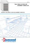
Watt 600
42
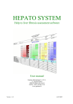
h. max. 150 mm. Gastronorm
2/1 - 1/1 - 2/3 - 1/2 - 1/3
°C +4/+10
Dati di collaudo • Test details • Détails d’essai • Prüfungsergebnisse • Datos de ensayo
230V/1/50Hz
MAX = (25°C - % U.R. 60)
R 404a
Kg. 95
Pastry & Ice Cream
Colibri
Restaurants
Accessorio
OPTIONAL
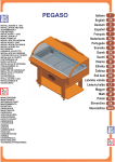
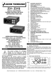
Apertura MANUALE delle cupole • MANUAL opening of the domes • Ouverture MANUEL des coupoles • MANUELLES öffnung der Kuppeln • Apertura MANUAL de las cúpulas
Vassoio unico per piatti pronti e pasticceria (fornito a richiesta) • For ready-to-serve dishes or pastry (supplied on request) • Plateau pour plats cuisines ou patisserie (fourni sur demande)
Ein Einziges Tablett für Patisserie oder Fertige Speisen (Lieferbar auf Anfrage) • Bandeja para platos listos o para pastelerias para llevar (bajo demanda)
Wine
Le vaschette GN sono fornite a richiesta • GN basins are available on request
• Les bacs sont fournis su demande • Die Schalen werden auf wunsch geliefert
• Las cubetera se entregan bajo pedido
Pegaso
Catering Equipment
Accessorio
OPTIONAL
Beverage Ice & Storage
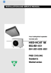
LxPxH: 1270x505x90 mm
Vassoio unico per piatti pronti e pasticceria (fornito a richiesta) • For ready-to-serve dishes or pastry (supplied on request) • Plateau pour plats cuisines ou patisserie (fourni sur demande)
Ein Einziges Tablett für Patisserie oder Fertige Speisen (Lieferbar auf Anfrage) • Bandeja para platos listos o para pastelerias para llevar (bajo demanda)
LxPxH: 1270x505x90 mm
57
Minimarket
Le vaschette GN sono fornite a richiesta • GN basins are available on request
• Les bacs sont fournis su demande • Die Schalen werden auf wunsch geliefert
• Las cubetera se entregan bajo pedido
COLIBRI
INSTALLAZIONE E USO
INSTALLATION AND USE
ZUSAMMENBAU
UND BETRIEB
INSTALACIÓN Y USO
INSTALLATION ET
MODE D'EMPLOI
INSTALLATIE EN GEBRUIK
INSTALAÇÃO E USO
INSTALLATION OCH BRUK
INSTALLATIONS OG
BETJENINGS
ASENNUS JA KÄYTTÖ
INSTALLATIE EN GEBRUIK
ÔÏÐÏÈÅÔÇÓÇ ÊÁÉ ×ÑÇÓÇ
INSTALACE A POUŽITÍ
UZSTĀDĪŠANA UN
EKSPLUATĀCIJA
INSTALACIJA IN UPORABA
PAIGALDAMINE JA
KASUTAMINE
BEÉPÍTÉS ÉS HASZNÁLAT
INŠTALÁCIA A POUŽITIE
INSTALACJA I
UZYTKOWANIE
ISTALLAZJONI U UżU
INSTALIAVIMAS IR
NAUDOJIMAS
MANUTENZIONE
MAINTENANCE
INSTANDHALTUNG
MANTENIMIENTO
ENTRETIEN
ONDERHOUD
MANUTENÇÃO
UNDERHÅLL
VEDLIGEHOLDELSESANVISNING
HUOLTO-OHJEET
ONDERHOUD
ÓÕÍÔÇÑÇÓÇ
ÚDRŽBA
APKOPE
VZDRŽEVANJE
HOOLDUS
KARBANTARTÁS
ÚDRŽBA
KONSERWACJA
MANUTENZJONI
TECHNINIS APTARNAVIMAS
I
UK
D
E
F
NL
P
S
DK
FIN
B
GR
CZ
EE
LV
LT
H
M
PL
SK
Slovenščina SLO
Italiano
English
Deutsch
Español
Français
Nederlands
Português
Svenska
Dansk
Suomi
Vlaams
Ellinika
Čeština
Esti keel
Latviešu valoda
Lietuvių kalba
Magyar
Malti
Polski
Slovenčina
Fig.1
I
UK
D
E
F
NL
P
S
DK
FIN
B
GR
CZ
EE
LV
LT
H
M
PL
SK
SLO
Fig.3
2
3
3
2
4
5
5
A
Fig.2
Fig.4
B
A
2
Fig.5
1
5
A
Fig.6
T
12.5
1
2
P
4
12.5
P
3
5
3
I
UK
D
E
F
NL
P
S
DK
FIN
B
GR
CZ
EE
LV
LT
H
M
PL
SK
SLO
6
11
M
~
10
12
M
~
2
7
55
9
I
UK
D
E
F
NL
P
S
DK
FIN
B
GR
CZ
EE
LV
LT
H
M
PL
SK
SLO
4
I
UK
D
E
F
NL
P
S
DK
FIN
B
GR
CZ
EE
LV
LT
H
M
PL
SK
SLO
1
8
56
12
3
5
I
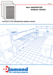
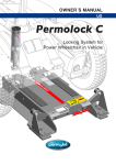
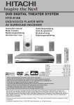
1)Bacinella 2)Compressore 3)Condensatore 4)Evaporatore 5)Filtro 6)Interruttore 7)Morsettiera
8)Motocompressore 9)Sonda 10)Spina 11)Termostato 12)Ventola condensatore
UK
1)Tray 2)Compressor 3)Condenser 4)Evaporator 5)Filter 6)Switch 7)Terminal board 8)Motor compressor
9)Probe 10)Plug 11)Thermostat 12)Condenser fan
D
1)Wanne 2)Kompressor 3)Verflüssiger 4)Verdampfer 5)Filter 6)Schalter 7)Klemmleiste
8)Motorkompressor 9)Sensor 10)Netzsteckdose 11)Thermostat 12)Gebläse Verflüssiger
E
1)Bandeja 2)Compresor 3)Condensador 4)Evaporador 5)Filtro 6)Interruptor 7)Caja de bornes
8)Motocompresor 9)Sonda 10)Enchufe 11)Termostato 12)Ventilador condensador
F
1)Bassine 2)Compresseur 3)Condenseur 4)Évaporateur 5)Filtre 6)Interrupteur 7)Bornier
8)Motocompresseur 9)Sonde 10)Prise de courant 11)Thermostat 12)Ventilateur condenseur
NL
1)Teiltje 2)Compressor 3)Koelinstallatie 4)Verdamper 5)Filter 6)Schakelaar 7)Klemmenbord
8)Motorcompressor 9)Sonde 10)Stekker 11)Thermostaat 12)Ventilator koelinstallatie
P
1)Cuba 2)Compressor 3)Condensador 4)Evaporador 5)Filtro 6)Interruptor 7)Terminal de bornes
8)Compressor motorizado 9)Sonda 10)Placa de união 11)Termostato 12)Ventilador condensador
57
I
UK
D
E
F
NL
P
S
DK
FIN
B
GR
CZ
EE
LV
LT
H
M
PL
SK
SLO
I
UK
D
E
F
NL
P
S
DK
FIN
B
GR
CZ
EE
LV
LT
H
M
PL
SK
SLO
I
UK
D
E
F
NL
P
S
DK
FIN
B
GR
CZ
EE
LV
LT
H
M
PL
SK
SLO
Manuale del manutentore
Maintenance manual
Wartungshandbuch
Manual de mantenimiento
Manuel du préposé à l'entretien
Onderhoudshandleiding
Manual do ténico de manutenção
Manual för underhållspersonalen
Vejledning til vedligeholdelsespersonale
Huolto-opas
Handleiding van de persoon belast met het onderhoud
Εγχειρίδιο συντηρητή
Pokyny pro údržbu
Hooldusjuhend
Instrukcija tehniskās apkopes darbiniekam
Techninio aptarnavimo darbuotojo vadovas
Karbantartási kézikönyv
Manwal għall-manutenzjoni
Podrecznik obslugi konserwacyjnej
Príručka pre údržbára
Priročnik za vzdrževalno osebje
46
Fig.1
I
UK
D
E
F
NL
P
S
DK
FIN
B
GR
CZ
EE
LV
LT
H
M
PL
SK
SLO
2
47
I
I
UK
D
E
F
NL
P
S
DK
FIN
B
GR
CZ
EE
LV
LT
H
M
PL
SK
SLO
1. PULIZIA DEL CONDENSATORE
1. Togliere l'alimentazione elettrica, agendo sull'interruttore a protezione della presa e sfilando poi la spina
dalla presa stessa. 2. Abbassatevi e nella parte sottostante la vasca vedrete il condensatore. 3. Con un
pennello eliminare lo strato di pulviscolo dalle alette del condensatore. 4. Con l'aspirapolvere togliere la
polvere residua. 5. Ripristinare l'alimentazione elettrica (Vedi Fig 1)
2. PULIZIA INTERNA e DEGLI EVAPORATORI
1. Togliere l'alimentazione.2. Operare uno sbrinamento totale. Rimuovere la merce ponendola in altro
luogo adeguatamente refrigerato alla stessa temperatura 3. Togliere il tappo dal centro del fondo vasca
(come illustrato in Capitolo 4). 4. Lasciare sbrinare gli evaporatori, evitando l'uso di corpi metallici taglienti
o appuntiti nel tentativo di rimuovere il ghiaccio. 5. Pulire le pareti e gli accessori, facendo attenzione alle
alette dell’evaporatore in quanto taglienti, con una spugna umida d'acqua e di un po' di bicarbonato di
sodio ed asciugare accuratamente.
UK
1. CLEANING THE CONDENSER
1. Use the power socket protection switch to switch off the power supply and then remove the plug from
the socket. 2. On the bottom, under the tank you will see the condenser. 3. Use a paintbrush to remove
the dust from the condenser's fins. 4. Use a vacuum cleaner to remove any remaining dust. 5. Switch the
power back on (see figure 1).
2. INTERNAL CLEANING AND EVAPORATOR CLEANING
1. Switch off the appliance. 2. Defrost the appliance. Remove goods and store them in another suitable
appliance running at the same temperature. 3. Remove the plug from the centre of the tank (as shown in
Chapter 4). 4. Allow the evaporators to defrost. Do not use sharp or pointed metal tools to remove the ice.
5. Clean sides and accessories with a sponge dipped in water and a little sodium bicarbonte and dry with
care.
D
1. KONDENSATORREINIGUNG
1. Schalten Sie den Strom ab, indem Sie den Schutzschalter der Steckdose betätigen und dann den
Stecker aus eben der Steckdose ziehen. 2. Wenn Sie sich bücken, können Sie im Bereich unter der
Wanne den Kondensator sehen. 3. Mit einem Pinsel den Staub von den Lamellen des Kondensators
entfernen. 4. Mit einem Staubsauger den restlichen Staub beseitigen.
5. Stromversorgung wieder herstellen (siehe Abb. 1)
2. REINIGUNG DES INNENBEREICHS und DER VERDAMPFER
1. Strom wie abschalten. 2. Vollkommmen abtauen lassen. Die Ware entfernen und an einem anderen,
ausreichend gekühlten Ort mit gleicher Temperatur unterbringen. 3. Verschluss im Zentrum des
Wannenbodens entfernen (wie im Kapitel 4 gezeigt). 4. Verdampfer abtauen lassen, wobei die
Verwendung von scharfen oder spitzen Metallgegenständen zum Entfernen des Eises vermieden werden
sollte. 5. Reinigen Sie die Wände und die Zubehörteile mit einem mit Wasser befeuchteten Schwamm
und etwas Natron und achten Sie darauf, sich nicht an den scharfen Lamellen des Verdampfers zu
schneiden. Sorgfältig abtrocknen.
48
Bedienungshandbuch
I
UK
D
E
F
NL
P
S
DK
FIN
B
GR
CZ
EE
LV
LT
H
M
PL
SK
SLO
Bedienungshandbuch:
1)Verpackungsöffnung.
2)Haubenöffnung
3)Reinigung der innenwanne
4)Aussenreinigung
5)Stützende abstandshalter der schalen und
gebäckablagen
6)Ablageflächen
7)Verbindung mit dem stromnetz
8)Einstellung
9)Betriebskontrolle
!
Wartungshandbuch (S. 48):
1)Kondensatorreinigung
2)Reinigung des innenbereichs und der verdampfer
3)Elektroschema, kühlanlageschema
SICHERHEITSHINWEISE
Wichtig! Aus Sicherheitsgründen muß man die Betriebsanleitung ständig am Einsatzort der Vitrine
griffbereit aufbewahren. 1. Arbeiten mit der Maschine dürfen nur von zuverlässigen Erwachsenen
durchgeführt werden. Kinder dürfen keinesfalls die Vitrine berühren, in der Nähe der Vitrine spielen oder
an den Regelschaltern spielen. 2. Es dürfen aus Sicherheitsgründen keine Modifikationen an der Vitrine
vorgenommen werden. 3. Arbeiten an elektrischen Teilen für die Montage der Vitrine dürfen nur von einer
Elektrofachkraft oder unter Aufsicht von Fachleuten durchgeführt werden. 4. Die Vitrine niemals
selbstständig reparieren. Die durch unqualifiziertes Personal durchgeführten Reparaturen können
Schäden und Funktionsstörungen verursachen. 5. Der technische Kundendienst dieser Vitrine darf nur
von einem Vertragshändler - Kundendienstservicestelle durchgeführt werden. Nur Originalersatzteile
verwenden! 6. Das Gerät ist nur für Lebensmittel geeignet! 7. Eine Haftung und Gewährleistung ist bei
Nichtbeachtung dieser Unfallverhütungshinweise ausgeschlossen. Änderungen und Verbesserungen
ohne vorherige Benachrictigung vorbehalten. 8. Aufstellung der vitrine bei direkter sonneneinstrahlung
vermeiden.9. Gerät nich in der Nähe von Wärmequellen wie Öfen, Heizkörper usw. nicht Aufstellen.
10. Sicherstellen, daß der abstand der Lüftungsgitter am Aggregat von der Wand mindestens 30cm
beträgt. 11. Denken Sie daran, dass die ausgestellten Produkte nicht über die Ablagen oder Gitter
hinnausstrecken dürfen.12. Sollte es durch die Luftfeuchtigkeit oder die zu kühlenden Produkte zu
außergewöhnlicher Bildung von Eis auf dem Verdampfer kommen, empfehlen wir, den Kompressor
auszuschalten und die Ware während des Abtauens bei gleicher Temperatur in dem vorgesehenen
Behälter aufzubewahren; andernfalls arbeitet der Kompressor ununterbrochen und verursacht einen
unnötigen Energieverbrauch sowie niedrige Leistung. 13. Die Tür für mindestens 10 cm. unbedingt offen
lassen, falls die Vitrine stillstehend und unbenützt bleiben sollte.
1. VERPACKUNGSÖFFNUNG
KARTONVERPACKUNG 1a. Das Band durchschneiden und den Karton nach oben herausziehen.
HOLZKISTENVERPACKUNG 1b. Vorsichtig die Nägel aus den Holzbrettern ziehen. 2. Die Gabeln des
Gabelstaplers zwischen Gerät und Palette oder Kiste schieben. 3. Gerät anheben. 4. Palette oder Kiste
entfernen. 5. Gerät auf eine ebene Abstellfläche setzen. 6. Es ist möglich, die Räder des Geräts mit der
Bremse zu blockieren. 7. Achten Sie darauf, dass sich nichts mehr in der Verpackung befindet, bevor Sie
sie fortwerfen. 8. Trennen Sie die Verpackung nach Materialien, um die Entsorgung zu erleichtern (siehe
Abbildung 1).
2. HAUBENÖFFNUNG
Fassen Sie den Handgriff und heben Sie die Haube an, bis sie blockiert (A) (siehe Abb. 2)
3. REINIGUNG DER INNENWANNE
1. Entfernen Sie die Schutzfolie vom Boden und von den Rändern. 2. Säubern Sie den Innenbereich und
die Scheiben mit einem weichen Schwamm und neutralen Reinigungsmitteln.
4. AUSSENREINIGUNG
1. Vermeiden Sie es unbedingt, abrasive Produkte oder Schleifschwämme zu verwenden. 2. Benutzen
Sie nur einen weichen, befeuchteten Schwamm. 3. Holzflächen mit im Handel erhältlichem
Spezialreiniger reinigen. Es handelt sich um lösungsmittelfreie Wasseremulsionen. 4. Mit einem
sauberen Tuch abtrocknen.
5. STÜTZENDE ABSTANDSHALTER DER SCHALEN UND GEBÄCKABLAGEN
1. Entfernen Sie die Schutzfolie von den Abstandshaltern. 2. Die längeren Abstandhalter an den Rändern
der Wanne anbringen. 3. Befestigen Sie die Schalen nach Belieben auf den dafür vorgesehenen
Abstandshaltern. 4. Für die Konditoreimodelle nur die Montage der Gebäckablage aus rostfreiem Stahl
ausführen, indem Sie sie auf den Rändern auflegen (die Schalen und die Gebäckablagen aus rostfreiem
Stahl werden auf Anfrage geliefert) (siehe Abb. 3).
8
Bedienungshandbuch
6. ABLAGEFLÄCHEN
1. Fassen Sie den unteren Rand der Ablagen mit den Händen und drehen Sie sie nach oben (A), bis sie
sich in horizontaler Stellung befinden. 2. Drücken Sie den Rand nahe der Wanne (B) nach unten, bis
sich jede einzelne Fläche blockiert. (Siehe Abb. 4)
7. VERBINDUNG MIT DEM STROMNETZ
1. Netzspannung und -frequenz müssen mit den auf dem am Gerät angebrachten Typenschild (A)
angegebenen Werten übereinstimmen. 2. Überprüfen Sie, dass die Steckdose: a) Mit einer Erdleitung
ausgestattet ist. b) Zu dem auf dem Schild angegebenen Nennstrom passt. c) Gemäß den IEC-Normen
mit einer Schutzvorrichtungen ausgerüstet ist: - Thermomagnetschalter mit In = auf dem Schild
angegebenem Nennwert. - Differenzial mit einer Ansprechempfindlichkeit von Id = 30 mA. 3. Versichern
Sie sich, dass am Aufstellungsort keine Explosionsgefahr besteht (AD). 4. Versichern Sie sich, dass der
Aufstellungsort für den Gebrauch des am Gerät angebrachten Speisekabels geeignet ist: Das
angebrachte Kabel: "H05 VVF" ist für Innenräume vorgesehen. Für andere Aufstellungsorte muss das
Kabel durch ein geeignetes ersetzt werden (z.B. mit dem Kabel HO 7 VV F für Außenbereiche).
NB: Wenn das Gerät während des Transports oder der Lagerung sich irrtümlicherweise in horizontaler
oder umgedrehter Stellung befand, lassen sie es mindestens 3 Stunden lang in der richtigen Position
ruhen, bevor sie es an das Stromnetz anschließen. 5. Stecker in die Steckdose stecken (keine
Dreifachstecker oder Verminderer verwenden) (siehe Abbildung 5).
8. EINSTELLUNG
Das Gerät ist mit Einstellsteuerungen ausgestattet, die sich in auf der Vorderseite befinden.
1. Kühlschalter: Zum Einschalten der Kühlanlage. 2. Thermometer: Gibt die Temperatur im Inneren des
Geräts an. Thermostat: Reguliert die Temperatur des Geräts. a) Das einmalige Drücken der Taste
3 “SET oder P” ermöglicht das Ablesen der voreingestellten Temperatur, die durch Drücken der Taste
4 “UP” oder 5 “DOWN” geändert werden kann. (siehe Abbildung 6).
9. BETRIEBSKONTROLLE
1. Der Stecker muss eingesteckt sein. 2. Der Schalter der Kühlanlage muss eingeschaltet sein und das
grüne Licht muss leuchten. 3. Das Thermometer muss einen für die Waren geeigneten Temperaturwert
anzeigen. 4. Das Gerät darf nicht der direkten Sonneneinstrahlung oder dem Licht von genau über dem
Gerät angebrachten Hochleistungsstrahlern ausgesetzt sein. 5. Die Raumtemperatur darf nicht über
+25°C - RF 60% liegen, für die das Gerät zugelassen ist (Klimaklasse 3). 6. Im Inneren des Geräts
dürfen keine direkten Luftströme bestehen, die von Türen, Fenstern, Ventilatoren oder Air-conditioningDüsen herrühren.
9
I
UK
D
E
F
NL
P
S
DK
FIN
B
GR
CZ
EE
LV
LT
H
M
PL
SK
SLO
and one input for PTC or NTC temperature probes. Furtheremore it can
be equiped with an internal buzzer to signalize the alarms and with a
configurable digital input.
TDF 12
MICROPROCESSOR-BASED DIGITAL
ELECTRONIC FREEZER CONTROLLER
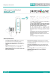
1.1 - FRONT PANEL
OPERATING INSTRUCTIONS
Vr. 01 (I - GB) - cod.: ISTR 00251
PREVIOUS STATEMENT: In this manual are contained all the necessary
information for a correct installation and the instructions for the use and
the maintenance of the product; we recommend, therefore, to read
carefully the following instructions. The maximum care has been used in
the realisation of this document, anyway TECNOLOGIC S.p.A. does not
assume any responsibility deriving from the use of itself. The same
consideration has to be done for each person or Company involved in the
creation of this manual. The herewith issue is an exclusive property of
TECNOLOGIC S.p.A. which forbids any reproduction and divulgation,
although partial, if not expressly authorised. TECNOLOGIC S.p.A.
reserves the right to execute aesthetically and functional modifications, at
any moment and without any notice.
INDEX
1
1.1
1.2
2
3
4
4.1
4.2
4.3
4.4
4.5
4.6
5
5.1
5.2
6
6.1
7
GENERAL DESCRIPTION
FRONT PANEL
INSTRUMENT CODE
TECHNICAL DATA
INSTALLATION
OPERATING MODE
ON/OFF CONTROL
COMPRESSOR PROTECTION FUNCTION
DEFROST CONTROL
MANUAL DEFROST
ALARM FUNCTIONS
DIGITAL INPUT
PROGRAMMING
PROGRAMMING OF SET-POINT
PROGRAMMING OF PARAMETERS
DESCRIPTION OF PARAMETERS
PARAMETERS TABLE
TROUBLES, MAINTENANCE, GUARANTEE
1 - GENERAL DESCRIPTION
TDF 12 is a digital microprocessor controller for Cooling applications
with temperature control by ON/OFF control mode and with defrost
control by stopping compressor mode. The process temperature value is
visualised on 3 red displays and the output state and the defrost state are
indicated by two led. The instrument has one output relay for compressor
1 - Key P : Used for the set point setting and to program the functioning
parameters
2 - Key DOWN : Used to decrease the values to be setted or to select
parameters
3 - Key UP/DEFROST : Used to increase the values to be setted or to
select parameters and to active manual defrost cycle
4 - Led SET : Signalize the set point programming mode (on) or the
parameters programming mode (flashing)
5 - Led OUT : Signalize the on output state (on), off (off) or inhibited
(flashing)
6 - Led AL : Signalize the on alarm state (on), off (off) or silented
(flashing)
7 - Led DEF : Signalize the on defrost state (on)
1.2 - INSTRUMENT CODE
TDF 12 a b c dd
a = SUPPLY
F : 12 VAC/VDC
G : 24 VAC/VDC
C : 110 VAC
D : 230 VAC
b = ALARM
- : Alarm not present
B : Alarm present by internal Buzzer
c = DIGITAL INPUT
- : Digital Input not present
I : With Digital Input
dd = SPECIAL CODES
-- : Not extractable terminal block, input for PTC probes (KTY81-121)
E- : Extractable terminal block, input for PTC probes (KTY81-121)
-N : Not extractable terminal block, input for NTC probes (103AT-2)
EN : Extractable terminal block, input for NTC probes (103AT-2)
2 - TECHNICAL DATA
ELECTRICAL DATA
Supply: 12, 24 VAC/VDC, 110, 230 VAC +/- 10%
Frequency AC: 50/60 Hz
Power consumption: 2 VA approx.
Input/s: 1 input for temperature probes PTC (KTY 81-121, 990 Ω at 25 °C)
or NTC (103AT-2 10 KΩ at 25 °C); 1 digital input for free-voltage
contacts.
Output: Relay (8A-AC1, 3A-AC3 250 VAC)
Electrical life for relay output: 100000 operat.
TECNOLOGIC - TDF 12 USER MANUAL (I - GB) - Vr. 01 - ISTR 00251 - PAG. 1
Protection class against electric shock: Class II for Front panel
Insulation: Reinforced insulation between the low voltage section (Supply
110 or 230 V and relay output) and the front panel; Reinforced insulation
between the low voltage section (Supply 110 or 230 V and relay output)
and the extra low voltage section ( inputs and supply 12 or 24 V); No
insulation between supply 12 or 24 V and inputs.
MECHANICAL DATA
Housing: Self-extinguishing plastic, UL 94 V0
Dimensions: 33 x 75 mm DIN, depht 64 mm
Weight: 160 g approx.
Mounting: Flush in panel in 29 x 71 mm hole
Connections: 2,5 mm2 screw terminal block
Degree of protection of front panel : IP 65 mounted in panel with gasket
Pollution situation: Normal
Operating temperature: 0 ... 55 °C
Operating humidity: 30 ... 95 RH% without condesation
Storage temperature: -10 ... +60 °C
FUNCTIONAL DATA
Temperature Control: ON/OFF
Defrost control: cycles by stopping compressor
Measurement range: PTC: -50...150 °C / -58 ... 199 °F; NTC: -50...50 °C
/ -58...122 °F
Display resolution: 1 ° in all range or 0.1 ° in range between -19.9 and
19.9
Overall accuracy: +/- 0,5 % fs
Sampling rate: 4 sample per second
Action: 1C type according to EN 60730-1
Compliance: ECC directive EMC 89/336 (EN 50081-1, EN 50082-1), ECC
directive LV 73/23 and 93/68 (EN 60730-1)
3 - INSTALLATION
MECHANICAL MOUNTING: The instrument, in case 33 x 75 mm, is
designed for panel mounting. Make an hole 29 x 71 mm and insert the
instrument, fixing it with the provided special bracket . We recommend to
mount the gasket to obtain an IP 65 front protection. Avoid to place the
instrument in areas with humidity or dirt. Connect the instrument as far as
possible from source of electromagnetic disturbances so as motors, power
relays, relays, electrovalves,etc.
ELECTRICAL
CONNECTIONS: Carry out the electrical wiring
connecting only one wire for each terminal , according to the following
diagram, check that the power supply is the same as indicated on the
instrument and the loads current is not upper than the maximum current
admitted. The instrument, being a built in equipment with permanent
connection into a cabinet, is not furnished with internal device protecting
from overcurrent : it's recommended , therefore, to properly protect all the
electric circuits connected to the instrument, with devices (ex. fuses)
proportionate to the circulating currents. It's strongly recommended to use
cables with proper insulation, according to the working voltages and
temperatures. Furthermore, the input cables has to be kept separate from
line voltage wiring. If the input cables is screened, it has to be connected
on the ground with only one side. It is advisable to check that the
parameters are those desired before connecting the outputs to the
actuators so as to avoid malfunctioning . Whenever a failure of the
instrument could cause dangerous or damaging situations, it should be
kept in mind that the plant has to be provided with additional devices to
ensure the safety. It's recommended to supply the instrument with supply 12
or 24 V using the Tecnologic TCTR transformer or equivalent type, and to
use one transformer for each instrument.
4 - OPERATING MODE
4.1 - ON/OFF CONTROL
The temperature control mode of the instrument by ON/OFF mode occours
on the output according to the Set point fixed and to the differential
switching point (par. "d") programmed. The regulator is intended for
cooling applications, for this reason the programmable differential is
always positive. The operating mode can be also modified by the
"Compressor Protection" function, see the next chapter for this function.
4.2 - COMPRESSOR PROTECTION FUNCTION
The function "Compressor Protection" is able, for cooling applications, to
protect the compressor against "short cycles" by introducing a delay on the
output activation. The parameters to be programmed for this function are:
"PS" : Protection type
- 1 - delay before start
- 2 - delay after stop
- 3 - delay between starts
"Pt" : Time delay setting for parameter "PS" (in min.)
The "Compressor Protection" function are automatically disconnected by
setting "Pt" = 0.
4.3 - DEFROST CONTROL
The automatic control of defrost, that is by stopping compressor, occours
according to this parameters:
"dC" : Defrost interval computation
- ct - based only on compressor running time (output on)
- rt - based on real time (instrument on)
"dI" : Interval between defrost cycles (in hrs)
"dE" : Lenght of defrost cycles (in min.)
4.4 - MANUAL DEFROST
To active manual defrost cycle press key UP /DEFROST, when you are'nt
in programming mode, and holding it down for about 5 seconds afterwhich
the led DEF will be on and the instrument will start a defrost cycle. The
manual or automatic defrost lenght is always programmable by par. "dE".
4.5 - ALARM FUNCTIONS
The instrument can be equiped with an internal buzzer used as probe alarm
signal, high and low temperature alarm or as external alarm trasmitted by
the digital input (if present). The temperature alarm function works
depending on the following parameters :
"HA" - High Alarm (relative to the Set Point)
"LA" - Low Alarm (relative to the Set Point)
"Ad" - Alarms (and fan) differential
"PA" - Alarm delay at power on (in hrs.)
"dA" - Alarm delay after defrost (in hrs.)
The alarm is operating at the end of the delays and will be on when the
temperature goes upper than the value [Set +HA] or goes lower than the
value [Set - LA]. The high and low temperature alarm can be disactivated
setting the relative parameters "HA" or "LA" at 0. When the alarm is
functioning to stop the buzzer push any of the programming key. In the
mean time of the alarm signalation, although the buzzer is silented, the
instrument signalize the alarm through the AL led and it visualize, during
the normal functioning:
- Alternatively "HI" and the temperature measure by the probe in case of
high temperature alarm.
- Alternatively "LO" and the temperature measure by the probe in case of
low temperature alarm.
- Alternatively "AL" and the temperature measure by the probe in case of
external alarm.
4.6 - DIGITAL INPUT
Furthermore the instrument can be equiped with a configurable digital
input. The digital input works depending on the following parameters:
"FI" - Digital input function
0 - Not active
1 - End defrost: when the input intervenes during a defrost cycle the defrost
ends and the defrost is inhibited
TECNOLOGIC - TDF 12 USER MANUAL (I - GB) - Vr. 01 - ISTR 00251 - PAG. 2
2 - Start defrost: when the input intervenes it's activated a defrost cycle.
With the input signal activated the instrument is always in defrost state.
3 - External alarm signalation: when the input intervenes the internal
buzzer (if present) is activated and the display shows alternatively "AL"
and the temperature measured by the probe.
"LI" - Digital input logic mode
on - Contact normally opened: the programmed function of "FI" parameter
works when the digital input contact is closed.
oF Contact normally closed : the programmed function of "FI"
parameter works when the digital input contact is opened.
5 - PROGRAMMING
5.1 - PROGRAMMING OF SET-POINT
Press key P then release it, led SET will flash and the SET value will be
shown on display. To modify press key UP so as to increase value or
DOWN so as to decrease it. These keys count one digit at a time but if the
keys are pressed for over one second the value increases or decreases fast
and after two seconds the speed increases even more, so as to reach the
desired value immediately. The outgoing from the Set programming mode
occurs automatically by not pressing any key for about 5 seconds, thus the
temperature process value will again be displayed.
5.2 - PROGRAMMING OF PARAMETERS
To accede to the operating parameters it is necessary to press key P
holding it down for about 5 seconds, afterwhich the led SET will flash and
the code of the first parameter will be visualized on the display. At this
point key P can be released and by pressing UP or DOWN the desired
parameter can be selected. Once the parameter on which we intended to
operate has been selected to modify it press P, than released it, the set of
the parameter will show up. To modify this value press UP or DOWN so as
to increase or decrease the value. Once the desired value has been set
press and than release P and the selected parameter code can be read on
the display. By pressing UP or DOWN it is therefore possible to choose
another one and modify it as previously mentioned. To outgoing from the
programming mode no key is to be pressed for about 20 seconds, the
instrument will automatically return to normal functioning mode,
visualizing the temperature process value.
dC - DEFROST INTERVAL COMPUTATION: Select the type of
computation for defrost interval as based on total compressor running time
(ct) or as based on real time instrument functioning (rt).
dL - DEFROST DISPLAY LOCK: Pemits the display visualization lock on
the last temperature reading (on) during all the defrost cycle until, at the
end of defrost, the temperature has not reached the value [Set + Et] (see
par. "Et") or is ended the time setted on par. "dA". Or it permits the
visualization of label "dF" (Lb) during the defrost cycle and, after the
defrost, of label "Pd" until, at the end of defrost, the temperature has not
reached the value [Set + Et] (see par. "Et") or is ended the time setted on
par. "dA". The display will otherwise continue to visualize the temperature
measured by the probe during the defrost cycle (oF).
Et - DIFFERENTIAL DISPLAY UNLOCK AFTER DEFROST :
Temperature differential to unlock the display after the defrost. If it's
utilized the option of "dL" parameter display lock during defrost, the
display,after defrost will come back to visualize the temperature measured
by the probe when it will be gone under the value [Set + Et].
PS - COMPRESSOR TYPE PROTECTION: Select the type of protection
for the compressor against "short cycle". The possibles selections are:
1 = delay before start
2 = delay after stop
3 = delay between starts
Pt - TIME DELAY COMPRESSOR PROTECTION: Time delay setting for
parameter "PS" intended in min.
od - OUTPUT DELAY AT POWER ON: Time delay of OUT relay
activation after power on and expressed in min.
HA - HIGH ALARM: Temperature value in respect with Set point above at
which the alarm will be on (The alarm will be on when the process
temperature will be upper then the value Set + HA).
LA - LOW ALARM: Temperature value in respect with the Set point below
at which the alarm will be on (The alarm will be on when the process
temperature will be lower then the value Set - LA).
Ad - ALARM DIFFERENTIAL: Value between starting and stopping of
alarm signal (par. HA and LA).
PA - ALARM DELAY AT POWER ON: Time delay after power on during
which the alarm will not be activated (expressed in hrs).
dA - ALARM DELAY AND UNLOCK DISPLAY DELAY AFTER DEFROST
: Time delay after a defrost cycle during which the alarm will not be
activated and during which the display (see par. "dL") is locked
(expressed in hrs).
FI - DIGITAL INPUT FUNCTION: It establish which function has to
realize the digital input.
0 = No function
1 = End defrost
2 = Start defrost
3 = External alarm
LI - DIGITAL INPUT LOGIC MODE: It establish if the digital input
causes the activation of the programmed function on par. "FI" when it's
closed (on) or when it's opened (oF).
SP - SET POINT : Set point value
6 - DESCRIPTION OF PARAMETERS
Here following are described all the instrument parameters; pls. note that
some of them could do not appear because are according to the kind of
used instrument.
CC - FIXED PARAMETER
CA - CALIBRATION: Positive or negative offset which is calculated on
probe reading before visualizing and to which the control functioning is
also connected. This parameter can be utilized when a recalibration of the
instrument is desired.
ru - UNIT OF MEASUREMENT: Determines the visualization of the
temperature in Centigrade or Fahrenheit degree. It is to be remember that
the change of this parameter modifies the visualization but not the Set and
the Set limit ("LS" and "HS") programmed (eg. if the Set was 50°C and the 6.1 - PARAMETERS TABLE
unit changes, the Set will rest 50°F).
Par.
Description
Range
dP - DECIMAL POINT : Allows the insertion of the decimal point on the
CC Fixed Parameter
display and therefore to determine resolution of the reading value in the
-15.0 .. +15.0
CA Calibration
range from -19.9 to 19.9 (on= with decimal point, oF= without decimal
°C - °F
point)
Unit of measurement
C-F
ru
d - DIFFERENTIAL SWITCHING POINT: Value between starting and
on - oF
dP Decimal Point
stopping of output OUT.
Differential switching point
0.0 ... 15.0
d
LS - MINIMUM SET: Minimum possible Set point value or lower limit of
°C - °F
Set point .
Minimum
Set
-58
... HS
LS
HS - MAXIMUM SET: Maximum possible Set point value or higher limit of
°C
- °F
Set point.
Maximum
Set
LS
...
199
HS
rP - OUTPUT RELAY STATE IN CASE OF ERROR PROBE: Select output
°C - °F
relay state in case of error probe (on = relay on, of = relay off).
Relay status in case of error
oF - on
rP
dI - DEFROST INTERVAL: Automatic defrost frequency. This time is
probe
calculated based on the selection of par. "dC" and is intended in hrs.
Defrost interval
0 ... 31 hrs
dI
dE - LENGHT OF DEFROST CYCLES: Determines the lenght of a manual
1 ... 99 min.
dE Lenght of defrost cycles
or automatic defrost cycle and is intended in min..
ct - rt
dC Defrost interval computation
TECNOLOGIC - TDF 12 USER MANUAL (I - GB) - Vr. 01 - ISTR 00251 - PAG. 3
Def.
0.0
C
oF
2.0
-50
150
oF
10
15
rt
Notes
od
HA
Defrost display lock
Differential display unlock
after defrost
Compressor type protection
Time
delay
compressor
protection
Output delay at power on
High alarm
LA
Low alarm
Ad
Alarm differential
PA
dA
Alarm delay at power on
Alarm delay and unlock
display delay after defrost
Digital input function
Digital input logic mode
Set Point
dL
Et
PS
Pt
FI
LI
SP
Lb - on - oF
0 ... 20
°C - °F
1-2-3
0 ... 31 min.
oF
2
0 ... 99 min.
0 ... 50
°C - °F
0 ... 50
°C - °F
1 ... 31
°C - °F
0 ... 99 hrs.
0 ... 99 hrs.
0
10
0-1-2-3
on - oF
LS ... HS
0
on
0.0
1
0
10
1
2
1
7 - PROBLEMS, MAINTENANCE AND WARRANTY
ERRORS SIGNALLING: The instrument shows the error message "--" ,
when the probe is interrupted or is in short-circuit and "uu" when is
underrange or "oo" when is in overrange. In this cases verify the correct
probe wiring with the instrument and afterward proceed to verify itself.
Furthermore the instrument can visualize the error message of the internal
memory "EE" , in this case verify, and if necessary, reprogram the
functioning parameters.
HOW TO CLEAN: We recommend to avoid abrasive cleaners or
containing solvents which could damage the instrument.
WARRANTY AND REPAIRS: The instrument is under warranty against
construction vices or defected material, noticed within 12 months from
delivery date.The warranty is limited to the repairs or to the substitution of
the instrument. The eventual opening of the housing, the violation of the
instrument or the wrong use and installation of the product means the
automatically decay of the warranty. In case of defected instrument,
noticed in warranty period or out of warranty, do contact our sales
department to obtain the shipment authorisation. The defected product
must be shipped to TECNOLOGIC with the detailed description of the
failures found and without any fees or charge for Tecnologic, safe
different agreements.
TECNOLOGIC - TDF 12 USER MANUAL (I - GB) - Vr. 01 - ISTR 00251 - PAG. 4