1
TXV00416_02 rev.1k.odt
Last change: 28.7.2011
FOXTROT – Control Your House!
CFox, RFox - Design and installation guide
Revision 1k
August 2011
Teco a.s. Havlíčkova 260, 280 58 Kolín, www.tecomat.com, www.controlyourhouse.com
1
TXV00416_02 rev.1k.odt
Last change: 28.7.2011
Content:
List of document updates................................................................................................................3
1 System overwiev, basic components...............................................................................................4
2 Basic module, Power supply...........................................................................................................5
2.1 Power supply..........................................................................................................................5
2.2 Basic module CP-1000, CP-1020..............................................................................................6
2.2.1 CP-1000, power without backup.........................................................................................6
2.2.2 CP-1020, power with backup.............................................................................................8
3 CIB bus, RFox network, TCL2 bus...................................................................................................9
3.1 CIB – the principles of design and installation..........................................................................9
3.1.1 CIB characteristics............................................................................................................9
3.1.2 Powering CIB buses – limitations, optimalisations..............................................................12
3.1.3 CIB master CF-1141........................................................................................................13
3.1.4 Coupling of CIB to the power supply – C-BS-0001M coupler..............................................15
3.1.5 Surge protection of CIB – DTNVEM 1/CIB and DTNVE 1/CIB..............................................16
3.2 RFox network – principles of design and installation................................................................18
3.2.1 RFox basic characteristics................................................................................................18
3.2.2 System function configurations, properties........................................................................18
3.2.3 RFox master RF-1131......................................................................................................20
3.2.4 RFox router R-RT-2305W.................................................................................................21
3.3 TCL2 system bus – principles of design and installation...........................................................22
4 Heating.......................................................................................................................................22
4.1 Hot water heaters – actuator control......................................................................................22
4.1.1 Motorized drive C-HC-0201F-E.........................................................................................24
4.1.2 Two-position drive Alpha AA controlled by relay output.....................................................25
4.1.3 Proportional drive Alpha AA 5004 controlled by 0÷10V signal.............................................26
4.2 Underfloor hot water heating.................................................................................................27
4.3 Underfloor electrical heating..................................................................................................28
4.4 Floor convectors – proportional control...................................................................................29
4.4.1 Floor convectors wit 24VDC EC motors (by ISAN)..............................................................29
4.4.2 Floor convector MINIB – connection to the Foxtrot system................................................30
4.5 FanCoils - control..................................................................................................................31
4.5.1 AERMEC FCXI – connection example................................................................................32
4.6 Boiler - Control and regulation of heating sources...................................................................33
5 Ventilation...................................................................................................................................34
5.1 Fan speed control, heat recovery units...................................................................................35
5.2 inVENTer - decentralized ventilation unit with heat recovery ...................................................36
6 Lighting......................................................................................................................................37
6.1 Switching LED lights..............................................................................................................38
6.1.1 Switching of external voltage or current switching power supply for LED power supply........38
6.2 Switching incandescent bulbs - 230 VAC or 12 VDC ................................................................40
6.3 Dimming of LED stripes, controlled by 12V or 24V voltage.......................................................41
6.4 Dimming of power LED, current supply for 350 mA, 500 mA, 700 mA, 1000 mA........................42
6.5 Dimming – DALI interface......................................................................................................43
6.6 Dimming of fluorescent lights and compact fluorescent lamps .................................................44
6.7 Dimming – Low voltage lights with inductive and electronic transformers..................................45
6.8 Dimming – incandescent lamps..............................................................................................46
6.9 Dimming – DMX512 control....................................................................................................47
7 Shutters, blinds...........................................................................................................................48
7.1 Controlling engines for outdoor shutters, awnings, etc. ...........................................................48
7.2 Control of DC motors for shutters and blinds...........................................................................50
8 Security Systems, Fire Alarm System............................................................................................51
8.1 Security sensors (PIR, …).......................................................................................................51
8.1.1 Configuration of inputs for Security sensors......................................................................51
8.1.2 Connecting securitz sensor with double balanced loop.......................................................52
Fire alarm systems – wiring of detectors......................................................................................52
9 Communication with the user.......................................................................................................53
2
TXV00416_02 rev.1k.odt
Last change: 28.7.2011
9.1 Wall switches flush mounted (Light control, shutters, etc.).......................................................53
9.1.1 Systém wall switches on CIB
To control lighting, blinds, ventilation and similar applications you can use the driver C-WS-0200R
with one gang and 2 buttons – one on top one on bottom and/or C-WS-0400R with two gangs and
4 buttons. Both types of drivers are made in the design of ABB Time and enable to attach up to
two temperature sensors: .......................................................................................................53
Indoor temperature with 12k NTC sensor available also in ABB's Time design............................53
Floor temperature with sensor fixed on the cable......................................................................53
9.1.2 Wall switches coupled to CIB over input module...............................................................54
9.1.3 Push buttons coupled over the module in cabinet..............................................................55
9.2 Displays and Heating control on the wall.................................................................................56
9.2.1 Heating control module C-RC-0002R-design......................................................................56
9.2.2 Heating, air conditioning, light control module RCM2-1......................................................57
9.3 Infrared control.....................................................................................................................58
9.3.1 IR transmitter and receiver C-RI-0401R-Time with the design on the wall...........................59
10 Temperature sensing................................................................................................................60
10.1 Room temperature measuring..............................................................................................61
10.1.1 Temperature sensor as CFox module in the wall design...................................................61
10.1.2 Temperature sensor as CFox module in the ABB wall design............................................62
10.2 Temperature measuring – with IP 65 housing.......................................................................63
11 Metering of energy and non-electric values.................................................................................64
11.1 Measurement of electric energy............................................................................................64
11.2 Connecting the electricity meter by optical probe according to standard EN 62056-21.............65
11.3 Heat and flow measurement................................................................................................66
11.4 Air quality measurement......................................................................................................67
11.5 Mains parameters measurement...........................................................................................67
11.6 Meteostation.......................................................................................................................69
11.7 M-bus meters integration, SX-1181 module...........................................................................70
11.8 M-bus meters integration – MR-0158 submodule...................................................................72
11.9 Measuring and monitoring of water level...............................................................................74
11.9.1 Continuous measurement of water level in the well or tank..............................................74
11.9.2 Limit monitoring water level in the well or tank...............................................................75
12 Control and monitoring of other technologies..............................................................................76
12.1 Defrosting of outdoor areas..................................................................................................76
12.2 Defrosting the gutters..........................................................................................................78
12.3 Pool technology control, integration.....................................................................................79
12.3.1 pH and Redox (chlorine) measuring................................................................................79
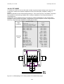
13 Design and installation information.............................................................................................80
13.1 Consumption of CFox modules from CIB or from external power supply..................................81
13.2 Module dimensions..............................................................................................................82
13.2.1 9M housing for DIN rail TS 35, according to EN 60715.....................................................82
13.2.2 6M housing for DIN rail TS 35, according to EN 60715.....................................................82
14 Basic application examples of CFox a Rfox modules.....................................................................83
14.1 C-OR-0008M, relay outputs, CFox.........................................................................................84
14.2 C-HM-0308M......................................................................................................................85
14.3 C-HM-1113M......................................................................................................................86
14.4 C-HM-1121M......................................................................................................................87
14.5 C-IT-0200S........................................................................................................................88
14.6 C-IR-0202S........................................................................................................................89
14.7 C-IT-0504S........................................................................................................................90
14.8 C-IT-0200R-Design.............................................................................................................91
14.9 C-DL-0012S........................................................................................................................92
14.10 C-RC-0002R.....................................................................................................................93
14.11 C-RI-0401R-Design, C-RI-0401R........................................................................................94
14.12 C-IT-0200I.......................................................................................................................96
14.13 RCM2-1............................................................................................................................99
15 Literature................................................................................................................................100
3
TXV00416_02 rev.1k.odt
Last change: 28.7.2011
List of Revisions
Rev.1k:
– Mistake in Fig 11.8.1 fixed (Wrong terminal numbers)
– Information about the Alpha AA thermostatic valves was added to chapter 4.1.2 a 4.1.3.
– Chapter added: 4.5.1 - Example of control of Fancoil FCXI.
– Chapter added: 11.9 - continuous and limit measurement of level in the tank.
– Chapter added: 13.1 -table of CIB modules consumption
– Chapter added: 9.3.1 - IR transmitter and receiver C-RI-0401
4
TXV00416_02 rev.1k.odt
Last change: 28.7.2011
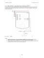
1 System overview, basic components
Foxtrot
•
•
•
control system can connect its peripherals by
CFox modules on CIB - Common Installation Bus,
RFox modules – Wireless
TCL2 bus for high speed PLC modules
Foxtrot basic modules CP-10xx are the central points of the system
The CP-1000 basic module is the right choice for installations where we do not assume to connect
sensors and actors directly to the basic module. Also for installations parametrized in the FoxTool.
The other Foxtrot basic modules (See Foxtrot design and installation guide TXV 004 11) ar suitable for
installations where all or majority of inputs and outputs should be connected directly to the basic
module.
Sensors like temperature sensors, push-buttons etc and actors like lights, valve, shutters and fan drives
are to be connected to the expansion modules via one of 3 buses above.
CIB - Common Installation Bus (CFox modules):
The major amount of peripherals in building automation are connected to CIB. The peripheral modules
are supplied with CFox brand. They are available in different housings especially for DIN rail mounting
in centralized cabinets, for flush box installation, in interior design for the wall mounting and also in the
IP65 housing. A detailed description of the CIB is shown in the following chapters.
RFox wireless network (bus):
Other possibility to install modules of Foxtrot system is wireless network RFox. It is not real bus, but
the modules are controlled by the same way as CFox modules on CIB. RFox modules are also available
in different housings – for DIN rail powered by 230VAC or 24VDC, for flush box – powered by battery
or 230VAC, in interior housing and in IP65 housing. Detailed descriptions of RFox modules are shown in
following chapters.
TCL2 bus:
It is the system bus of PLC. There is not so wide range of types of peripheral modules. The bus has to
be wired strictly as linear line and it has other strict requirements for installation. Detailed description of
the TCL2 bus is in the TXV 004 11 manual. Peripheral modules on the TCL2 bus are available only for
DIN rail installation. In building control installations, this bus is often used to connect external master
modules CFox (CF-1141) and RFox (RF-1131) or some communication modules like Open Therm and
MP-Bus.
Input and output modules connected via any bus above are equal from the point of programming,
parametrization and configuration. Only RFox modules powered from batteries has slight differences
like longer period of refresh of the new value, measuring the battery status …
To switch the light it is not important if the light is connected to the relay output of CFox, RFox, TCL2
module or directly to the relay on the basic module.
Apart the initial configuration the programmer need not take care about which relay is used
5
TXV00416_02 rev.1k.odt
Last change: 28.7.2011
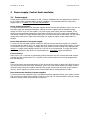
2 Power supply, Foxtrot basic modules,
2.1 Power supply
System Foxtrot and the CFox modules on CIB - Common Installation Bus are supplied by the 24VDC or
by 27,2 VDC in case of battery backup of all the installation. The accepted tolerance of the power
supply output is in chapter 3.1.1 with the CIB description.
Power supply parameters:
It is highly recommended to use the power supplies specified in this documentation even if you can use
also other types with adequate parameters. Majority of power supplies with the stabilized output
voltage 27.2 VDC or 24 VDC are suitable. The power supply must comply the SELV standard, 27.2V
supply must be specifically designed for direct battery charging. Also power supply with stabilized 24
VDC output voltage (for system without backup) can be used. Extra care must be taken over the output
voltage since some power supply with extra power can supply the higher output voltage than it is
allowed.
Power determination of the power supply:
To power the CP-1000 itself (without modules on CIB) can be used the power supply min. 15W like
recommended type DR-15-24. If you supply also other modules from the same power supply, you have
to increase the power accordingly. To supply the basic module and both internal buses CIB (see also
chap.2.2.1. Supply without backup) DR-60-24 or DR-100-24 is recommended. To supply the system
with battery backup the PS2-60/27 is recommended (see . chap.2.2.2. Supply with backup).
Fuse Protection:
Input power (27V + terminal) is protected by internal electronic fuse. We recommend install external
external fuse with nominal value of T3 15L250V for the central module CP-10x0 fully equipped with
both CIB branches.
SELV:
If the power supply meets the parameters of the source SELV according to EN 60 950 (ČSN 33 2000-441), then all I/O circuits meet SELV accordingly. Even if the relay outputs switch low voltage circuits it
meets the requirement since isolation between relay output and the internal circuits of the system is
4kV AC). Power supplies for system Foxtrot recommended above meet parameters of SELV.
Improvement the reliability of power supplies:
To ensure trouble-free operation even in exceptional situations (lightning effects, poor quality of power
grid or influence of other devices with the recourse to the grid it is recommended for the power supply
230VAC to install suitable surge protection equipment.
6
TXV00416_02 rev.1k.odt
Last change: 28.7.2011
2.2 Foxtrot Basic modules
The following chapters describe the basic modules CP-1000 and CP-1020. The other Foxtrot basic
modules (eg, CP-1006, etc..), including the principles of usage and their installation are described in the
Foxtrot design and installation guide, TXV 004 11.
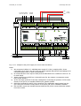
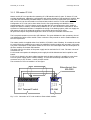
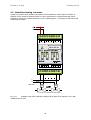
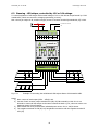
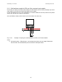
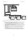
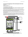
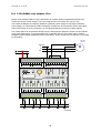
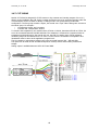
2.2.1 CP-1000, example of powering without backup
CP-1000 is the simplest variant of the basic module for home and building installation.
The basic module is powered from 24 VDC power supply. Both branches of CIB on connector B are
powered directly over the basic module. No other module is necessary to power the CIB buses. All
coupling components are integrated directly in the basic module CP-1000.
The system bus TCL2 is available on connector A, especially for external masters CF-1141 and RF-1131.
Serial communication channel CH1 is usually used for a GSM modem.
On the connector D the slot for other communication interface is placed. The optional sub-modules
inserted to this slot enable to implement interfaces such as RS485, M-Bus Master, CAN, RS232 and
more. Possible variants of interface sub-modules are described in Foxtrot design and installation guide,
TXV 004 11
The E and F connectors enables connecting auxiliary inputs and outputs: 4 universal AI/DI (for
contacts, NTC, Pt1000, Ni 1000), 2 independent relay outputs 3A, input for HDO (as signal of low
tariffication of electricity distributor) and input IN 230 VAC (as standard binary input 230 VAC).
Backing up the internal data and time of CP-1000 during the power failure:
When power of CP-1000 falls down, the selected user data and calendar and clock are backed up. Back
up is provided by internal Li-Ion battery. After power is restored the battery recharges and is ready to
back up again. The battery requires no maintenance. Li-Ion battery backup will last approximately 500
hours.
Additional internal backup battery
If the backup time has to be increased (eg. to switch-off the power supply for more than 500 hours),
the additional lithium battery of CR2032 type can be inserted into the ready to insert holder. After
discharge of the Li-Ion battery this CR2032 will provide power and extend the backup time up to
20,000 hours.
Preventive replacing of the backup battery type CR2032 or equivalent, (3 V, diameter 20 mm, thickness
3.2 mm), it is recommended at intervals of 2-3 years. Battery life is typically 5 years. The battery has to
be inserted in the holder located on the inner board and the basic module and is accessible after
removing the plates from the plastic cover (more information is available in basic documentation of
each module).
7
TXV00416_02 rev.1k.odt
Last change: 28.7.2011
CIB1
to external masters
CF-1141, RF-1131
+
+
–
to GSM
modem
2x CIB
powered
CIB 2
–
OUTPUT 24 V DC / 2,5 A
CTS
TxRx-
TxRx+
RxD
-
TxD
TxRx-
TxRx+
AGND
AI0
DI0
AI1
DI1
AI2
DI2
AI3
DI3
D4
D5
D6
D7
D8
D9
E1
E2
E3
E4
E5
E6
E7
L
BT+
D3
N
RTS
BT-
D2
E8
E9
F1
F2
L
N
PE
C7
C8
GND
C9
GND
C6
GND
C5
POWER 27 VDC
IN 230 VAC
DO0
GNDS
GNDS
D. OUTPUT
D1
C4
HDO
F3
D. OUTPUT
F4
F5
F6
F7
F8
DO1
DIGITAL/ANALOG INPUTS
C3
ACU 24 VDC
CI BUS 2
+5 V
+5 V
CH2 SUBMODULE (e.g. RS-232, RS-485)
C2
L
CI BUS 1
C1
COM2
B9
+27V
B8
+27V
B7
+27V
B6
N
CIB1-
CH1/RS-232
B5
GND
B4
+24V
B3
CIB2-
B2
CIB2-
B1
CIB2+
A9
CIB2+
A8
COM1
TC LINE
A7
CIB1-
A6
CIB1+
A5
CIB1+
A4
TxD
A3
RTS
A2
RxD
A1
GND
N
GND
L
TCL2+
230 V AC
TCL2-
DR-60-24
F9
+24 V
0V
230 VAC
24 VDC SELV
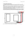
Fig. 2.2.1.1. Example of the power supply of CP-1000 without a backup
Notes:
1) We recommend a DR-60-24 - stabilized power supply of 24 VDC, complying SELV. Power
consumption of CP-1000 is the sum of its own power (typically 3W) and the total wattage of all
connected modules CFox on both of CIB branches.
2) On terminal B there is the output of both powered CIB branches for a maximum current of 1 A
for each branch.
3) Inputs to AI/DI0 up-to AI/DI3 are 4 universal inputs (for dry contacts or temperature sensor
NTC, Pt1000, Ni1000).
4) IN 230 VAC input (terminals F1 and F2) is designed for monitoring the presence of 230V mains
directly on the grid. It is a standard 230VAC input, galvanic isolated.
5) HDO input (terminals F4 and F5) is for connection of the tariffication signal coming from the
grid. This input is tolerant to many failures of the power grid even to installation mistakes.
6) DO0 and DO1 outputs are standard electromechanical relay 3A the contact electrically isolated
from other circuits.
8
TXV00416_02 rev.1k.odt
Last change: 28.7.2011
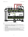
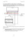
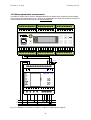
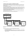
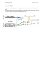
2.2.2 CP-1020, example of backup powering
The CP-1020 basic module on the contrary to CP-1000 is equipped with an internal master of RFox
network. Together with 2 x32 peripheral modules on the two branches CIB bus you can directly
connect up the 64 RFox peripheral elements on the basic module. Antenna output is on the front panel
as SMA connector.
The antenna has to be placed according to the best RF coverage of the desired amount and placement
of all RFox modules. You can use either a short antenna fitted directly to the SMA connector, or a
vertical whip antenna connected over the 2 m cable with SMA connector. More information about RFox
network elements are presented in chapter 3.2. Other features are consistent with the basic module
CP-1000, see the previous chapter.
Using Foxtrot also for security purposes, it is essential to back up all the system by batteries. The
power supply must be capable of providing power from battery for the required period and vice versa it
must ensure the continuous charging of the backup battery. For this purposes the PS2-60/27 power
supply with output voltage 27.2V DC is recommended. It can supply the system and charge the
batteries.
PS2-60/70 has also output of 12 VDC, max 300 mA for security sensors. This power supply is active
even when running applications from connected batteries. For backup, it is necessary to use two
encapsulated lead-acid batteries 12V DC (typically with a capacity of 7 Ah to 28 Ah) connected in series
- see following figure.
The presence of AC voltage 230 VAC in the mains can be detected at input IN 230VAC (mains voltage
connected to terminals F1 and F2). The basic module measures the value of the main supply voltage
(ie voltage at terminal C). The state of the input IN 230VAC and voltages can be evaluated as the
presence of mains voltage 230VAC so running from the battery and measuring the voltage we can
indicate a time upcoming discharge (by SMS, etc.).
9
TXV00416_02 rev.1k.odt
Last change: 28.7.2011
CIB1
2x CIB
powered
CIB 2
12 V
to external masters
CF1141, RF-1131
+
+
+
–
–
to GSM
modem
T 3,15 A
12 V
záložní AKU
2 x 12 V
–
E1
E2
E3
E4
E5
E6
E7
E8
E9
F1
F2
L
N
PE
C8
C9
GND
C7
GND
C6
GND
C5
HDO
F3
D. OUTPUT
F4
F5
F6
F7
F8
DO1
D9
L
TxRx+
D8
N
TxD
TxRx-
D7
C4
POWER 27 VDC
IN 230 VAC
DO0
RxD
-
D6
AI3
DI3
TxRx+
D5
AI2
DI2
CTS
TxRx-
D4
AI1
DI1
BT+
D3
AGND
RTS
BT-
D2
D. OUTPUT
AI0
DI0
GNDS
GNDS
D1
C3
ACU 24 VDC
CI BUS 2
DIGITAL/ANALOG INPUTS
+5 V
+5 V
CH2 SUBMODULE (e.g. RS-232, RS-485)
C2
L
CI BUS 1
C1
COM2
B9
+27V
B8
+27V
B7
+27V
B6
N
CIB1-
CH1/RS-232
B5
GND
B4
+24V
B3
CIB2-
B2
CIB2-
B1
CIB2+
A9
CIB2+
A8
COM1
TC LINE
A7
CIB1-
A6
CIB1+
A5
CIB1+
A4
TxD
A3
RTS
A2
RxD
A1
GND
N
GND
U
TCL2-
230 V AC
TCL2+
PS50/27
OUTPUT 27,2 V DC / 1,9 A
F9
+24 V
0V
230 VAC
24 VDC SELV
Fig. 2.2.2.2. Example of the power supply of CP-1020 with a backup
Notes:
1) We recommend PS2-60/27 - stabilized power supply of 27,2 VDC, complying SELV. Power
consumption of CP-1020 is the sum of its own power (typically 4W) and the total wattage of all
connected modules CFox on both of CIB branches.
2) On terminal B there is the output of both powered CIB branches for a maximum current of 1 A
for each branch.
3) Inputs AI/DI0 up to AI/DI3 are 4 universal inputs (for dry contacts or temperature sensor NTC,
Pt1000, Ni1000)
4) IN 230 VAC input (terminals F1 and F2) is designed for monitoring the presence of 230V mains
directly on the grid. It is a standard 230VAC input, with galvanic isolation.
5) HDO input (terminals F4 and F5) is for connection of the tariffication signal coming from the
grid. This input is tolerant to many failures of the power grid even to installation mistakes.
6) DO0 and DO1 outputs are standard electromechanical relay 3A the contact electrically isolated
from other circuits.
10
TXV00416_02 rev.1k.odt
Last change: 28.7.2011
3 CIB bus, RFox network, TCL2 bus
3.1 CIB – the principles of design and installation
CIB bus enables to connect CFox peripheral modules to the Foxtrot basic module. CFox modules are
intended for building and home automation, for HVAC etc. but they can be used in any application as a
standard I/O respecting their characteristics.
CIB bus is master/slave. One CIB master enables to connect max. 32 slave modules. CP-1000 and CP1020 has 2 embedded and powered CIB masters. Other basic modules CP-10x4, CP-10x5, CP-10x6 and
CP-10x8 have only one CIB master. More CIB slaves can be connected via external CIB masters CF1141. Each CF-1141 contains 2 powered CIB masters for 2x 32 CIB slave modules. Max. 4 CF-1141
modules so totally 8 CIB masters can be connected to one Foxtrot basic module.
CF-1141 modules have to be connected via TCL2 system bus See chap. 3.3
3.1.1 CIB characteristics
CIB – Common Installation Bus is 2 wire bus with arbitrary topology. The communication is modulated
and superimposed on the DC supply voltage. CIB bus can be powered by the standard power supply
27,2VDC or 24VDC coupled by the couplers embedded in basic modules CP-1000/1020, in CF-1141 or
by standing alone coupler C-BS-0001M. Such power supply can supply the basic module at the same
time.
Besides the communication over 2 wires, CIB bus enables to power all connected modules. The care
must be taken only about the max. voltage drop along the wires so the voltage on the most remote
module should be within recommended tolerances
Rated voltage of the CIB bus (with backup)
Rated voltage of the CIB bus (without backup)
Topology
Max. distance between master and most remote slave
1)
27,2 VDC
24 VDC
Arbitrary
about 500 m
+ 10%, - 25%
+ 25%, - 15%
´
1)
Max. length of one branch is mostly limited by the voltage drop along the cable. Also at the most
remote module there must be voltage within the tolerances seen above
For the CIB wiring can be used any 2 wire (or more) cables. However it is recommended as a good
practice to use the shielded twisted pairs with the wire diameter 0,6mm at least, the optimum is 0,8
mm (with the resistance of the wire approx. 7 Ω / 100 m), e.g. J-Y(St)Y1x2x0,8, or YCYM 2x2x0,8.
The cross-section and topology has to be designed primarily with respect to voltage drops in cables
according to amount of CFox modules.
Basic rules for CIB installation
– CIB bus enables arbitrary topology – line, star, tree. Only avoid to enclose the circle!
– It is recommended to minimize the parallel layout of CIB and power cables (with 230VAC) as a
good practice. It depends on the real possibilities at the site. But no special requirements and
limitation for it is not set.
– For larger installations the voltage drops along the whole installation has to be checked to
eliminate the voltage below the tolerance at each CIB module.
– The galvanic isolation of inputs and outputs in each module should be taken into account
during the installation. Only modules declared for 230VAC usage have safe galvanic isolation
always.
– CIB installation has to be designed always with respect to SELV or PELV safety requirements
Basic rules for shielded cable usage:
– The shield of the internal and external wires in the cabinet has to be connected only at one
side and to the main protective earth PE of the cabinet – together with the earth rack of the
cabinet.
– At the metallic cabinet the shield of the external cables are to be connected at the entry into
the cabinet directly to the metallic case.
11
TXV00416_02 rev.1k.odt
–
–
–
Last change: 28.7.2011
At the plastic cabinet the shield of the external cables are to be connected as close as possible
at the entry into the cabinet directly to the base metallic mounting plate.
The shield is connected by cross section as large as possible directly to the grounded areas of
cabinet (base plate etc.). In case of using terminals, the unraveled and then twisted shield
should be used.
The shield cannot be connected using extension wires.
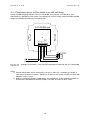
Fig. 3.1.1.1
Example of the shield wiring in the cabinet
Variants:
a) The shield of the incoming cable is connected with the ground using the special metallic cable
entry ready to made for shielding with the outer case of cabinet (like Progress MS EMV by IES
see the picture). This way is the most efficient since it minimizes the emitting interferences into
the cabinet. The earthing of the shield is provided by the earth terminal, base plate and
protection terminal.
b) The shielding of the external cables is connected with the ground by the metal clips, mounting
plates and protective clamps. Shield of the inner cable is connected to the ground via
grounding clamps, mounting boards and protective clamps. This or another similar method is
particularly suitable for plastic panels with a metal mounting plate.
c) The inappropriate way to connect the shield is shown as c on the picture. Cable shielding is
indeed associated with protective terminal, but the connection wire degrades shielding
effectiveness and long loop is being introduced so the radiation of electromagnetic interference
is introduced into the cabinet.
12
TXV00416_02 rev.1k.odt
Last change: 28.7.2011
3.1.2 CIB powering – limitations, optimizations
Amount of modules on the CIB branch.
Max. number of CFox modules connected to one branch/one master is 32. This number cannot be
exceeded.
On the contrary the number of modules in the CIB branch must be reduced in case of using more
modules with the higher consumption from CIB like C-HM-1113M. It is in order to avoid the exceeding
of the maximum current supplied from the master and coupled from power supply. See the relevant
documents of CIB master or CIB coupling module.
It is always useful to calculate the total consumption of modules to be ensured if the CIB branch will
not be overloaded.
Reducing the load (reducing the consumption) of CIB.
The most of peripheral CFox modules are powered from CIB. There exists several modules like C-HM1121M (supplied from the mains 230VAC) or C-OR-0008M (optionally powered from external 24 or 27,2
VDC), which enables to connect the higher amount of inputs outputs on the CIB without need to be
supplied from CIB.
Dividing large installation among more CIB branches.
In case of large installation application with more CIB buses it is useful to take it into account the
consumption of each module during the planning the wiring topology. It is a good practice not to wire
all relay modules on one CIB branch and on the other one only temperature sensors. In such case the
first branch will be overloaded while the power capacity of the second one will stay not fully used. It is
always useful to spread the load over all branches to achieve the reliable compliance of topology,
amount of modules and load of each CIB. It is a good practice to save the capacity of each branch for
the future extensions.
13
TXV00416_02 rev.1k.odt
Last change: 28.7.2011
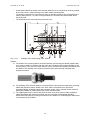
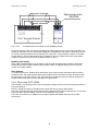
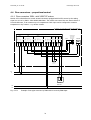
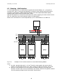
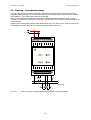
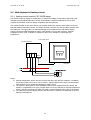
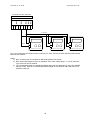
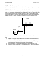
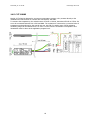
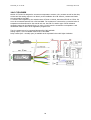
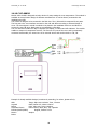
3.1.3 CIB master CF-1141
Master module CF-1141 provides the mastering of 2 CIB branches each for max. 32 slaves. CF-1141
provides identification, addressing, configuration and regular operation of CIB peripheral¨modules. Also
it provides the data handling and data transfer to Foxtrot over the TCL2 system bus (see chap.3.3.)
Max. 4x CF-1141 can be connected to one Foxtrot basic module each for 2x CIB masters.
Configuration of CF-1141 can be done either from the free programming tool MOSAIC or from
parametrization SW – FoxTool. Master module provides also the auto-diagnostics, which enable to
analyze the status of module, communication statistics etc. CF-1141 has also the terminals for direct
connection of backup accumulator. It simplifies the wiring of the backup system, which can supply the
CIB master as well as all peripheral modules on the CIB bus during the fail of mains.
All inputs and outputs are protected against the short circuit by the reversible electronic fuse.
The front panel contains one two-color LED indicator. The green indicates the bus operations, the red
one indicates the failure of the module. There is also the rotary encoder to set the module address on
the TCL2 system bus.
The master module is supplied either from 24VDC or 27,2VDC in case of backup. It contains the circuits
to couple CIB to the standard power supply. No additional coupling modules are necessary in this case.
The power consumption of the master module is sum of its own consumption and the consumptions of
all slave modules on the both CIB branches.
The same rules for the choice of the power supply can be used also for CF-1141. The max. current of
each branch is 1A.
For this total consumption the adequate power supply should be dimensioned and coupled for each
branch.
If CF-1141 is placed in the same cabinet together with the basic module it is possible to power them
from one power supply (with or without backup). In such case the backup accumulator is to be
connected only to one of them – usually to basic module.
The connection of CF-1141 module is on the figure.
Zakončovací člen
KB-0290
GND
TCL2+
GND
TCL2-
TCL2+
PLC Tecomat Foxtrot
TCL2-
A1 A2 A3
A1 A2 A3 A4 A5 A6 A7 A8 A9
CF-1141
Fig. 3.1.3.1. Connection of CF-1141 module to Foxtrot basic module.
14
TXV00416_02 rev.1k.odt
Last change: 28.7.2011
12 V
12 V
+
to CP-1020
záložní AKU
2 x 12 V
+
+
+
–
–
+
T 3,15 A
–
TCLÌ
A5
A6
A7
A8
GND
POWER 27VDC
PWR
4 5
BACKUP
ACU 24V
ACU
BU
6
7
8
9
CF-1141
ADR
CIB1
PWR2
B4
B5
B6
CIB2+
B3
CIB2+
CIB1-
B2
CIB2
CIB1-
B1
CIB1+
CIB1+
CIB1
CIB2
B7
B8
CIB2-
PWR1
CIB2-
3
2
1
0
A9
UB+
A4
GND
A3
+24V
A2
GND
A1
+27V
N
GND
U
TCL2-
230 V AC
TCL2+
PS2-60/27
OUTPUT 27,2 V DC / 2,2 A
B9
CIB 2
L
N
PE
CIB1
2x CIB
powered
230 VAC
Fig. 3.1.3.2.2. Connection of CF-1141 with backup accumulators.
Notes:
1) We recommend a PS2-60/27 - stabilized power supply of 27,2 VDC, complying SELV. Power
consumption of CF-1141 is the sum of its own power (typically 1W) and the total wattage of all
connected modules CFox on both of CIB branches.
2) There is the outputs of both powered CIB branches on terminal B for a maximum current of 1 A
for each branch.
3) The backup accumulators should be encapsulated lead-acid type with the capacity from 7Ah up
to 28 Ah. The capacity is calculated from the total consumption and the period which the
system should be backup.
4) In case of current presence of both CF-114 and the Foxtrot basic module, the backup output
(A8, A9 terminals) can be used to power both of that modules. Backup accumulator is
connected only to CF-1141.
15
TXV00416_02 rev.1k.odt
Last change: 28.7.2011
3.1.4 CIB coupling to the power supply – C-BS-0001M coupler
The coupler C-BS-0001M enables the proper coupling of the the power supply to CIB separating the
communication pulses of all CFox modules from the power supply.
Module is available in the 1M box for DIN rail mounting. On the front panel the green LED indicates
right voltage on the module output. The output is protected by the reversible electronic fuse against
the short-circuit on the CIB.
C-BS-0001M is designed to exceed the power of internal coupler in the CP-10x4/10x5/10x6/10x8 basic
modules. They have limited capacity to power full loaded CIB or for older Foxtrot basic modules which
have no coupler inside.
Maximum current for CIB powering from this module is 1A. For this load the power supply has to be
dimensioned.
16
TXV00416_02 rev.1k.odt
Last change: 28.7.2011
3.1.5 CIB surge protection – DTNVEM 1/CIB and DTNVE 1/CIB
In case the CIB installation has the potential of over-voltage appearance e.g. the parallel layout along
the lighting conductor or the part of CIB is wired outside the building, it is NECESSARY to use the surge
protection properly. Since the unique features of CIB bus, only special surge protections can be used.
Using the other types can essentially reduce the reliability as well as the functionality of CIB installation.
For CIB bus there are two surge protections available
Both of them have the identical electrical characteristics, they differ only by form factor.
DTNVEM 1/CIB
1M housing for DIN rail mounting with the screw-type terminals.
DTNVE 1/CIB
for flush or under cover installation with the 10 cm isolated wire outlets.
Surge protection DTNVEM 1/CIB is the basic protection element for the CIB . It protects against the
over-voltage which can appear only in the bus. It does not substitute protection of all the control
system. The main surge protection of the whole system is always the protection of power supply i.e.
properly designed and installed protection of 230 V AC power supply. The protection the main power
supply has to be inherent part of each system design. All the principles of installation of surge
protection as they are generally known should be used to protect the 230 VAC power supply.
DTNVEM 1/CIB is Surge Protection Device (SPD) according to EN 61643-21 (category A2, B2, C2, C3,
D1) designed to protect CIB against lightning currents and surges. The recommended location is the
input line from outside into the building, as well as on border with other LPZ (Lighting Protection Zones
according to EN 62305) and close to the protected device, so that the cable length between the overvoltage protection device and the protected equipment should be less than 10 m.
DTNVEM 1/CIB consists of a base and replaceable module that contains the protection itself. The base
is still attached so in case of inspection or damage one can handle only with replaceable module. The
base is not removable so the CIB wiring is not interrupted.
The protection is designed for continuous current up to 0.5 A. It is necessary to ensure in the project
design that this current will not be exceeded.
DTNV 1/CIB engages output toward the protected equipment.
Fig. 3.1.5.1. Internal circuit of surge protection DTNVEM 1/CIB (same is for DTNVE 1/CIB)
The DTNVEM 1/CIB surge protection always should be in front of the part of the bus we want to
protect. So we need to protect all parts of the installation leaving the zone ZBO1, or installing along
the large metal parts of buildings that are in zone 0, eg. lightning conductor). We must protect
individually all parts of each installation, which the above theorem applies.
17
TXV00416_02 rev.1k.odt
Last change: 28.7.2011
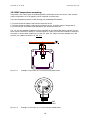
In Figure 3.1.5.2 we have outlined an example where the installation is done with CIB inside the house.
The main part of the installation ③ is located inside of the protected object and its protection is
implemented on the system power supply 230 V (protection covers the entire application - a central
unit and bus unit).
Part of the units ② are located in an adjacent building - garage, which leads the CIB bus cable laying in
the ground. It is necessary to install protection always at entry point into the building. So that both
parts of the installation are protected against ingress of over voltage which may occur in the cables in
the ground.
One unit is located under the roof ① (eg, wind speed meter). CIB wiring goes along the lightning rod
mounted outside on the perimeter wall. Suitable place for surge protection is on the end of parallel
layout with the lightning rod. The unit ① - is unprotected, but the rest of the application is protected
properly.
BLESKOSVOD
DŮM
IM2 -140M
VOUT 27 VDC
R
1
GARÁŽ
3
2
IM2-140M
VOUT 27 VDC
R
IM2-140M
VOUT 27VDC
R
OUTPUT
DTNVEM 1/CIB
HES
DTNVEM 1/CIB
DTNVEM 1/CIB
OUTPUT
INPUT
CIB
OUTPUT
CENTRAL
UNIT
CIB
INPUT
INPUT
Fig. 3.1.5.2. Typical protection variants by DTNV 1/CIB
18
EZS
FIRE
...
TXV00416_02 rev.1k.odt
Last change: 28.7.2011
3.2 RFox – principles of design and installation
RFox is wireless mesh network operating like a bus. It is operated in accordance with the ERC
RECOMMENDATION 70-03 RELATING TO THE USE OF SHORT RANGE DEVICES (SRD). For operations
in unlicensed radio band 868 MHz no additional permission is required. RFox bus is always composed of
one master and up to 64 slaves - peripheral I/O modules. Master of the network can be implemented
as an external DIN rail mounted module connected by TCL2 system bus. Wireless peripheral modules
are available in different form factor for the interior, for mounting on DIN rail in cabinets, hand-held
remote controls, ....).
3.2.1 RFox - basic characteristics
RFox network is designed to be compliant with the ERC Recommendations mentioned above. The
system is designed not to increase the load of the environment by the additional radio wave operations.
Transmit power is about 3.5 mW (maximum allowed is 25 mW) and the system is designed to minimize
radio operations to a minimum time. It uses low power to achieve higher battery life cycle of batterypowered modules. Minimal transmitting power also eliminates an impact on human health.
Standard system configuration satisfies the maximum 1% duty cycle, although due to the
implementation of the LBT (listen before talking) the duty cycle is not limited.
It uses the multichannel operations and there are 8 channels as a standard available in the frequency
range g1 (868.000 to 868.600 MHz, according to general authorization).
3.2.2 RFox – functions, configurations, properties
Communication among RFox master and RFox slave is supported for star and mesh topology
Star topology means the direct wireless access between master and slave, master always
communicates with all slaves directly
Fig. 3.2.2.1
Example of star topology
19
TXV00416_02 rev.1k.odt
Last change: 28.7.2011
Mash topology means such placement of slaves, where the master has direct access only to some
slaves. The other slaves are accessible only through the routers. Router (repeater) receives the RF
packet, and transmit it in the air. Using the routers it is possible to increase the basic range of RFox
master accessibility.
Fig. 3.2.2.2
Example of Mesh topology.
In one RFox mesh network max. 4 routers can be used. Transmitted RF packet has to reach its
destination using max. 5 hops. Each hop increase the delay between the transmitting and receiving the
RF packet. It means delay between command and action.
Any RF module with permanent operations can works as router as well. The router function can be
assigned to any RF module during RFox network configuration procedure.
Concerning the regular operations, there exist RFox modules with continuous operations and modules
with interrupted operations.
Modules with continuous operations are able to follow the master commands anytime. They are usually
continuously powered.
Modules with the interrupted operations (usually battery operated) stay the most of time in the sleep
mode. In the sleep mode they do not answer on the master commands. They operates only for a short
time. They are waked up by the user defined function as the push of the button or by time schedule.
20
TXV00416_02 rev.1k.odt
Last change: 28.7.2011
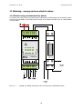
3.2.3 RFox master RF-1131
RFox master implements the wireless communication with peripheral modules and transmits the data
via TCL2 system bus to the Foxtrot basic module. Master is available in two variants. Either as an
internal part of Foxtrot basic modules CP-102x and CP-103x and referred internally as RF-1130 or as an
external peripheral module on TCL2, referred as RF-1131. We recommend to use external master since
it gives much better result concerning the distance of access.
One RFox master can handle up to 64 peripheral RF modules. The Foxtrot basic module can control one
up to 4 external masters RFox, together 256 wireless modules.
120 R
R
TCL2-
GND
TCL2+
GND
TCL2TCL2+
RUN RF
3
2
1
0
4 5
6
7
8
9
ADR
GND
GND
+24V
RF-1131
+24 VDC
GND
Fig. 3.2.3.1
Connection of terminals of RFox master RF-1131
External master RF-1131 is to be connected to the PLC via TCL2 system bus on the A1 to A3 TC
terminals referred as TCL2.
21
TXV00416_02 rev.1k.odt
Last change: 28.7.2011
PLC Tecomat Foxtrot
Fig. 3.2.3.2
GND
TCL2+
GND
TCL2-
TCL2+
A1 A2 A3 A4 A5 A6 A7 A8 A9
TCL2-
Zakončovací člen
KB-0290
RF-1131
Connection RF-1131 module to PLC TECOMAT Foxtrot
At the PLC side the TCL2 bus has the impedance terminal inside the PLC. On the side of the RF-1131
module is necessary to fix the termination impedance. Completing can be done by KB-0290 (TXN 102
90, 120Ω) connected between the terminals TCL2+ and TCL2-. The terminator is a part of Tecomat
Foxtrot delivery. If the communication line Termination has to be always done at the most remote
module on the whole line in case of multiple modules on TCL2!
Module power supply
RFox master requires 24VDC to be supplied. It can be used the same power supply for both basic
module and for external RFox master. Internal RFox master is supplied directly from the internal
circuits of the basic module.
RFox antenna
To enable the access to wireless RFox network the screw type antenna with SMA coaxial connector
should be used. The small antenna fixed on the module can be used. Also the external antenna with
the connector on the cable can be used. This second one enables to place the antenna outside the
metallic cabinet and also to find the best place for radio waves.
3.2.4 RFox router R-RT-2305W
R-RT-2305W is one purpose router which increases the range of access of RFox network by means of
the mesh topology.
Router is a plug-in version for 230VAC power outlet and has one green LED indicator
The router provides receiving the RF packet and its subsequent RF packet forwarding on. In one RFox
network (under one RFox master) you can use a maximum of 4 routers.
The router form factor of an adapter into an outlet 230VAC and besides the plug has no other
connections.
22
TXV00416_02 rev.1k.odt
Last change: 28.7.2011
3.3 TCL2 system bus – principles of design and installation
Detailed description of TCL2 characteristics and the rules for wiring you can find in documentation [4].
The modules UC-1204 – Open Therm communication module, or UC-1203 – MP bus for drives by
Belimo which can be used in building or HVAC automation are also described in documentation [4].
23
TXV00416_02 rev.1k.odt
Last change: 28.7.2011
4 Heating
Foxtrot system allows to realize solutions from simple one such as regulation and control of a gas boiler
with radiators through complex assemblies with floor convectors, underfloor heating up to complex
managing of multiple sources of heating like heat pumps, gas boilers, automatic boilers for liquid and
solid fuel, solar hot water systems and also comfortable heating and cooling with fan coil units, ceiling
cooling, remote controlled air conditioning units as well as controlled ventilation with centralized or
decentralized recuperation.
4.1 Hot water heating – valve control
The standard radiator valves can be controlled electrically. The scope of such valves is very wide and
they are manufactured in many types of different size, power, opening and closing time, of different
control, power supply, normally open or closed with the possibilities of various screw toward the valve
and toward the price.
CIB powered drives C-HC-0201F-E or C-HC-0101F can be used for standard applications of hot water
panel radiators. These drives are powered directly from the CIB bus. They use the motor with
proportional 0-100% setting of the valve position.
C-HC-0101F has an extremely low power consumption about 0.6 W during the positioning. It is
mechanically identical with the RFox drive R-HC-0101F.
C-HC-0201F-E is a smaller drive, the positioning takes more power then the previous one. It allows
connect 2 external sensors (eg. Temperature and window contact).
In case of wireless installation, the battery powered valve RFox R-HC-0101F should be used. This drive
is powered by one or two AA batteries 3.6 V.
Other possibility is to use standard electrically controlled on/off drives and switch them by relay outputs
or by analog output 0÷10V.
The 24VDC voltage level for control is preferable due to the electrical safety – access of children. The
disadvantage of this version is the necessity to install wires for 24VDC power.
The 230VAC is available practically everywhere and no 24VDC has to be wired.
The proportional controlled valves 0÷10V enable better feedback control but the price is rather high.
Alpha AA drives are recommended.
These drives have large range of adapters for standard and less standard radiator valves on the
market. They have smart design and several versions of control. The list of drives available:
AA Alpha 230 NC
230VAC powered, normally closed
AA Alpha 230 NO
230VAC powered, normally open
Alpha AA 24V DC/AC NC
24 VDC/AC powered normally closed
Alpha AA 24V DC/AC NO
24 VDC/AC powered normally open
Alpha AA 0-10V proportional
24 VDC/AC powered, control signal: 0 to 10V
Selection of the operating voltage is determined according to the customer needs.
The choice between the drives normally closed or normally open depends on customer preferences to
minimize power consumption (controlled radiators in the insulated house will be closed most of the
year so the normally closed drives bring higher efficiency), or the customer requires normally open
valves so during the blackout the valves stay open.
The drive and adapter must be ordered according to the specification of radiator valve manufacturer.
24
TXV00416_02 rev.1k.odt
Last change: 28.7.2011
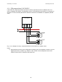
4.1.1 CIB powered drive C-HC-0201F-E
C-HC-0201F-E is CIB powered drive and can be used for proportional control of radiator valve. The
drive is equipped with auxiliary 2 analog/binary inputs. It has standard screw M30x1,5 for mounting on
the valve. For other mounting dimensions reduction accessories are available as a separately ordered
items.
NTC 12k
NTC 12k
AI2
AI1
GND
CIB-
CIB+
C-HC-0201F-E
Fig. 4.1.1.1 Example of wiring – Motorized CIB drive C-HC-0201F-E for radiator valves.
Notes:
1) Motorized drive has two inputs configurable as analog inputs for temperature sensors or as two
digital inputs for dry contacts e.g. window or door contact. So the temperature sensor and
window contact can be connected at the same time.
25
TXV00416_02 rev.1k.odt
Last change: 28.7.2011
4.1.2 Alpha AA - Two-position drive controlled by relay output
To switch this drive any relay output in the system can be used. The typical consumption of the drive is
about 3W when energized. As a local switch of drive C-IR-0202S module is suitable. Equipped with the
3A and relatively quiet relay and with 2 general purpose inputs for temperature and window sensors it
is smart solution. Be careful about the noise of relay switching in the bedroom.
Any relay output like outputs on the C-HM-1113, etc. can be used to switch the two-position drive from
the centralized cabinet.
DO1
COM1
AOUT1
AI2
AI1
CIB-
GND
CIB+
C-IR-0202S
L
N
230 VAC
Fig. 4.1.2.1 Connection example of two-position drives for radiator valves.
Notes:
1) Alpha AA drives (230 VAC i 24 VDC/AC) have the continuous consumption about 1,8 W. Power
supply and circuit protection must be dimensioned for peak current during switch on (up to 300
mA per one drive for up to 2 minutes). Also other electrically controlled actuators of most
manufacturers have similar consumption.
Basic parameters of the two-position drives Alpha AA:
Termodrive ALPHA AA
AA
AA
AA
AA
2004 /
2104 /
4004 /
4104 /
Supply Voltage
Function
230 V NC 230 V AC, +10% .. -10% Normally closed
50 ÷ 60 Hz
230 V NO
Normally open
24 V NC 24 V AC, +20% .. -10% Normally closed
0 (DC) ÷ 60 Hz
24 V NO
Normally open
26
Peak
current
max.
300 mA for
max. 200 ms
250 mA for
max. 2 min.
Continuous
current
8 mA
75 mA
TXV00416_02 rev.1k.odt
Last change: 28.7.2011
4.1.3 Alpha AA 5004 - Proportional drive controlled by 0÷10V signal
This drive can be controlled by any analog output 0 ÷ 10V of system Foxtrot. To control the drive
locally, the C-IR-0202S seems to be most appropriate. It is equipped with analog output (0 ÷ 10V) and
two inputs for room temperature and for the window contact. Supplying more drives from one common
source of 24VAC it is highly recommend to take care about the galvanic connection of the analog
outputs of each CIB module and the 24VDC power supply for drives. The negative potential of the
power supply is connected with negative potential of the CIB bus through the analog output circuits. It
is necessary to keep the minimum voltage difference between that two signals. Use the same cable
topology, sufficient cross-section of CIB wires as well as of 24VAC power supply wires.
DO1
COM1
AI2
AOUT1
AI1
GND
CIB-
CIB+
C-IR-0202S
24 VAC
Fig. 4.1.3.1 Connection example – proportionally controlled drive for radiator valve.
Notes:
1) For control of AA 5004 drive it is necessary to take care about the continuous consumption
about 1,8 W per drive (Peak current 200 mA for max. 2 minutes per each drive)
2) Input impedance of analog input of AA 5004 drive is 100 kOhm.
3) If you want to supply more drives from a common 24VAC power supply, you must take care
about the galvanic connection of the power supply and CIB over analog input of the drive. CIB
bus and power supply 24 VAC must have strong wires and be installed together.
4) For the bigger cable length like tens meters, the motorized CIB drives or two-position drives
should be used.
27
TXV00416_02 rev.1k.odt
Last change: 28.7.2011
4.1.4 Alpha AA 5004 – two-position drive controlled by RCM2-1
The RCM2-1 has one SSR (Solid State Relay) output, which enables direct control of the valve drive
(Alpha AA) powered by 24V AC/DC. Max. current is 600mA. The output has galvanic isolation from
other circuits of RCM-1.
Fig. 4.1.4.1
Example of two-position drive of radiator valve controlled by RCM2-1
Notes:
1) The SSR output is only for low safe voltage of 24VAC/DC. The output load can have any
polarity. It is possible to use SSR output in the same way as the relay contact.
2) To switch bigger load than 600mA (e.g. more drives) SSR can control standard auxiliary relay
mounted in the flush box, which can switch bigger load.
28
TXV00416_02 rev.1k.odt
Last change: 28.7.2011
4.2 Underfloor heating -hot water
A3
A4
A5
A6
A7
CIB+
COM1
AI1
DI1
AI2
DI2
AI3
DI3
GND
CIB LINE
ANALOG/ DIGITAL INPUTS
A8
A9
AO2
A2
AO1
A1
CIB-
Usually two-position drives located in the splitter can be switched by several types of modules. It
depends on the number of branches and/or on other requirements for measurement and control.
Example of control of a 6-splitter actuators is on the following figure. It is possible to place the C-HM0308 along the splitter.
A. OUTPUTS
B2
B3
B4
B5
B6
B7
B8
COM3
DO6
DO5
DO4
DO3
DO2
COM2
B1
DO1
DIGITAL OUTPUTS
B9
L
N
230 VAC
6x HLAVICE S VENTILEM V ROZDĚLOVAČI
Fig. 4.2.1
Example of hot water underfloor heating with 6 valves for 6 branches. The C-HM0308M module is used
29
TXV00416_02 rev.1k.odt
Last change: 28.7.2011
4.3 Underfloor heating - electrical
B2
B3
B4
B5
B6
B7
B8
B9
NO2
B1
NC2
A9
DO2
A8
NO1
CIB-
CIB LINE
A7
NC1
CIB-
A6
DO1
CIB+
A5
GND
A4
GND
A3
+24V
A2
+24V
A1
CIB+
Heating cables or heating mats must be switched by relay outputs according to the switched current.
The relays of C-OR-0202B for flush mounting can be used with the possibility of simultaneous
measuring of floor temperature. Also the C-OR-0008 can be used to switch up to 8 branches. It can be
placed in the distribution cabinet next to circuit breakers for individual heating branches. Also RFox
wireless module R-OR-0008M can be used powered by 24VDC from power supply DR-15-24. For
wireless control RFox network must be installed.
DIGITAL OUTPUTS
POWER 24 VDC
HW ADDRESS 19AE
C9
D1
D2
D3
D4
D5
NO8
NC7
C8
NC8
DO7
C7
NO7
NO6
C6
DO8
NC6
C5
DO6
NC4
C4
NO5
DO4
C3
NC5
NO3
C2
NO4
NC3
C1
DIGITAL OUTPUTS
DO5
DO3
DIGITAL OUTPUTS
D6
D7
D8
D9
L
N
230 VAC
R
R
TOPNÝ
KABEL
Fig. 4.3.1
R
TOPNÝ
KABEL
R
TOPNÝ
KABEL
R
TOPNÝ
KABEL
R
TOPNÝ
KABEL
TOPNÝ
KABEL
Example of electrical underfloor heating switched by C-OR-0008M
Notes:
1) Protection by circuit breakers have to be dimensioned according to the power of each heating
cable, max. 16A per branch.
30
TXV00416_02 rev.1k.odt
Last change: 28.7.2011
4.4 Floor convectors – proportional control
4.4.1 Floor convectors ISAN - with 24VDC EC motors
Module C-FC-0024X allows to control several convectors equipped with 24V EC motors by the analog
signal 0 to 10V or by PWM – Pulse Width Modulation. The module can control also two electric drives of
hot and cold water, it can measure up to 3 temperatures. Each input can be configured to measure
temperature or dry contact – e.g. window contact.
PODLAHOVÝ KONVEKTOR
CIB FANCOIL CONTROLLER C-FC-0024X
WSb
+24V
D1
B1
D2
B2
D3
B3
D4
B4
D5
B5
C1
A1
C2
A2
C3
A3
C4
A4
C5
A5
C6
A6
C7
A7
C8
A8
0V
t
TEPLOTA
VÝMĚNÍKU
NTC 12k
+24V
2
1
0V
OKENNÍ
KONTAKT
CIB+
CIB-
Fig. 4.4.1.1
Example of two-pipe convector by ISAN with EC motor by EBM Papst
31
TANGENCIÁLNÍ
VENTILÁTOR
EC motor 24V
EBM PAPST
WINDOW
SENSOR
WSa
TS2b
TEMP.
SENS.2
TS2a
TS1b
TS1a
TEMP.
SENS.1
CIB -
CIB -
CIB +
CIB +
0V
CIB
0V
COLD
COLD
HEAT
0V
HEAT
0V
AOUT
+24V
AOUT
+24V
0V
0V
+24V
+24V
VALVE
OUTPUTS
FAN
OUTPUT
INPUT
IN
POHON
1
2
3
4
5
1
2
TXV00416_02 rev.1k.odt
Last change: 28.7.2011
4.4.2 Floor convector MINIB – connection to the Foxtrot system.
Convector is equipped with only the control block EB. Heating valve is mounted in a splitter or can be
mounted directly in the convector. Convector is not equipped with additional sensors like frost
protection. Convector with the EB controller is powered by 12V AC from TT100 transformer (230 V/12 V
AC, 100VA). In this example the ALPHA AA4104 drive is used (24V, NO).
B2
B3
B4
AO1
AO2
COM2
DI1
DI2
DI3
ANALOG INPUTS
B5
B6
B7
B8
B9
DI8
B1
DI7
A9
DI6
A8
DI4
A7
DI5
A6
AI3
COM1
A5
GND
CIB+
CIB LINE
A4
AI2
A3
AI1
A2
CIB-
TT100
A1
PE N
L
L1 L2
DIGITAL INPUTS
A. OUTPUTS
230 VAC
L
N
PE
C9
D2
D3
D4
D5
D6
D7
D8
COM7
D1
DO11
DO10
DO6
DO5
C8
DO9
C7
COM6
C6
DO8
C5
DO4
COM4
DO3
C4
COM5
C3
DIGITAL OUTPUTS
DO7
C2
DO2
COM3
C1
DO1
DIGITAL OUTPUTS
D9
24 VDC
(nebo 24 VAC)
+24V
0V
1
2
3
4
EB
KONVEKTOR
MINIB
VENTIL TOPENÍ
Fig. 4.4.2.1
Example of control of the MINIB convector equipped by the EB control block
32
5
6
TXV00416_02 rev.1k.odt
Last change: 28.7.2011
4.5 Fan Coils
A3
A4
A5
A6
A7
CIB-
COM1
AI1
DI1
AI2
DI2
AI3
DI3
GND
CIB LINE
ANALOG/ DIGITAL INPUTS
A8
A9
AO2
A2
AO1
A1
CIB+
NTC 12k
NTC 12k
Fan coil units are manufactured in various designs from the control point of view. Following figure
shows the typical configuration with the 3-speed fan, two-position drives for heating and for cooling
circuit. The figure shows also how to connect the condensation sensor and two temperature sensor.
Additionally C-HM-0308 module can provide also the control of proportional speed drives, proportional
speed control of EC motor by two (0-10V) outputs etc.
A. OUTPUTS
B1
B2
B3
B4
B5
B6
B7
B8
COM3
DO6
DO5
DO4
DO3
DO2
DO1
COM2
DIGITAL OUTPUTS
B9
230 VAC
L
N
N
I
II
III
M
VENTILÁTOR
3-OTÁČKOVÝ
VENTIL TOPENÍ
VENTIL CHLAZENÍ
Fig. 4.5.1 Example of control of four-pipe Fan Coil with 3-speed fan.
33
TXV00416_02 rev.1k.odt
Last change: 28.7.2011
4.5.1 Fan Coil AERMEC FCXI – connection example.
A4
A5
A6
A7
AI1
DI1
AI2
DI2
AI3
DI3
GND
CIB LINE
ANALOG/ DIGITAL INPUTS
A8
A9
AO2
A3
AO1
A2
CIB-
CIB+
A1
COM1
NTC 12k
NTC 12k
Inverter fan coils AERMEC FCXI and FCLI are available in 2- and 4-pipe design. Also FCXI-P version is
on the market without housing just for mounting into air ducts in the ceiling or in the false wall. The
installation in the parapet niche is also possible. Fan-coil AERMEC FCXI and cassette fan coil FCLI
allows proportional control of fan motor speed (0 – 100%). Thus the smooth air flow, cooling and
heating is enabled.
A. OUTPUTS
B2
B3
B4
B5
B6
B7
B8
COM3
DO6
DO5
DO4
DO3
DO2
COM2
B1
DO1
DIGITAL OUTPUTS
B9
230 VAC
L
N
PE
10 9
8
7
6
5
4
3
2
1
FAN-COIL
FCXi AERMEC
Fig. 4.5.1.1 Example of connection of FCXI fan coil by AERMEC
Notes:
1) For 2-pipe fan coil unit FCXI only the valve actuator is connected to terminals 3 and 4 is
controlled.
2) For 4-pipe fan coil unit the heating actuator is on terminals 3-4, the cooling terminal is on
terminals 1-2, drives are powered from 230 VAC.
34
TXV00416_02 rev.1k.odt
Last change: 28.7.2011
4.6 Heating - Boilers
Boilers for gas, automatic pellet, automatic coal, etc. can be controlled by any relay output in the
system Foxtrot. In the more complicated set of heat sources it is recommended to limit or to avoid the
own "intelligence" of the boiler like ekviterm heating curve, etc. The optimal control algorithm of the
boiler should be discussed with the specialist and should be integrated in the Foxtrot system. This
allows you to set, to change, to monitor the behavior of the whole system directly in the Foxtrot,
including all remote management tools, supervision and service.
In a similar way you can control also heat pumps, which do not have intelligent communication with
the control system of the house. The room thermostat input can be used to master the heat pump.
Boilers equipped with Open Therm interface can be controlled using the UC-1204 module. Example of
connection to the Thermona boiler equipped by IU05 interface including connection principles is
documented in [4].
4.7 Heating – Heating pumps
Heat pumps equipped with a communication interface can communicate with Foxtrot usually by the
same interface. In case of heat pump driven by Foxtrot as an inherent part of heat pump, it can be
connected to an intelligent home control system via Ethernet. It can also be used for better control and
sharing parameters. E.g. it is possible to add the setting parameters of heat pump to the website of the
house and handle all as one entity. The data transfer between the heating pump and Foxtrot managing
the whole house must be coordinated with the heat pump supplier or manufacturer.
35
TXV00416_02 rev.1k.odt
Last change: 28.7.2011
5 Ventilation
Ventilation and heat recovery units are supplied with its own controller, which often can not be
integrated into building management system. It is therefore preferable to control ventilation units with
the heat recovery directly by Foxtrot. Foxtrot is equipped with a range of input/output modules suitable
for this purpose. Library of function blocks ready to control ventilation, heat recovery units, fan coil
units, etc. is expanding step by step. The advantage of this solution is the flexibility of hardware where
custom control of ventilation can be combined with other technologies. The SW and HW of the control
system can be configured accordingly.
List of I/O modules for different ventilation systems:
Fans:
Discrete speed control of 230V motors
relay modules,
eg. C-HM-0308M
Variable speed of 230VAC asynchronous motor - embedded
C-FC-0230X
Variable speed of 24 VDC EC motors, embedded
C-FC-0024X
Variable speed of 24 VDC EC motors, 0÷10V control
Eg. C-HM-0308M
Variable speed of motors with inverters, 0÷10V control
Eg. C-HM-0308M
Sensors:
Temperature sensors
Eg. C-HM-0308M
Condensation sensors
C-HM-xxxxM
CO2 sensor in interior design
C-AQ-0001R
Servo-drives:
3-point controlled servo-drive 230V or 24V
Relay modules
eg. C-HM-0308M
Analog 0÷10 V controlled servo-drive
AOUT,
eg. C-HM-03308M
Damper actuator, 1-point control
Relay modules
eg. C-HM-0308M
Servo-drive with protocol MP-Bus
UC-1203
It is also possible to control the electric heater by 16A relay outputs, e.g. C-OR-0008.
It is also possible to read inputs from sensors (filter, etc..) from the remote control (e.g., manual
control of the bathroom, etc.)
36
TXV00416_02 rev.1k.odt
Last change: 28.7.2011
5.1 Heat recovery system - Fan speed control.
NTC 12k
NTC 12k
The figure shows an example of control of heat recovery unit with two fans with EC motors, actuator
and valve, up to three temperature sensors, all connected to one module C-HM-0308M
EC MOTOR
VENTILÁTOR
IN
A2
A3
A4
A5
A6
A7
A8
A9
CIB+
CIB-
COM1
AI1
DI1
AI2
DI2
AI3
DI3
GND
AO1
AO2
+24V
A1
CIB LINE
ANALOG/ DIGITAL INPUTS
0V
M
EC MOTOR
VENTILÁTOR
A. OUTPUTS
IN
+24V
0V
M
+24V
0V
B1
B2
2
3
B3
B4
B5
COM3
DO5
DO6
DO4
DO3
DO2
COM2
DO1
DIGITAL OUTPUTS
B6
B7
B8
1
2
3
B9
230 VAC
L
N
1
LM230A
KLAPKOVÝ POHON
1-BODOVÉ ŘÍZENÍ
LM230A
KLAPKOVÝ POHON
3-BODOVÉ ŘÍZENÍ
37
TXV00416_02 rev.1k.odt
Last change: 28.7.2011
5.2 Heat recovery system – decentralized ventilation unit inVENTer
To power and control up to two independent inVENTer ventilation units the C-VT-0102B module was
designed. The module is fully powered from the CIB bus. The maximum output power is 5W.During the
operation of two fans. So the the module loads the CIB like about 5 normal CIB modules.
The module is equipped with an input for an external temperature sensor for interior or exterior
temperature.
Two inVENTer units – the fans - are connected directly to module outlets A1 and A2, respectively B1
and B2. The order of wires is not so important . It can be corrected in the module configuration
procedure.
V1
V2
PŘIPOJOVACÍ KONEKTORY inVENTer
NTC 12k
C-VT-0102B
Fig. 5.2.1
Example of connections two fans of inVENTer system
Notes:
1. As temperature sensor on TSa, TSb terminals can be used: NTC 12k, NTC thermistors can have
max. 160kOhm.
2. Fans of inVENTer units are to be connected directly on the wire outlets by max. 15m long wires
3. Module C-VT-0102B has the consumption 5W at max. speed of both fans
38
TXV00416_02 rev.1k.odt
Last change: 28.7.2011
6 Lighting
Light source classification:
LED stripes and LED powered by low voltage typically 12VDC, 24VDC.
Light intensity is controlled by the voltage. See module C-DM-0006M-ULED. Recommended way how to
switch the LED power supplies is in the chapter 6.1.1.
Power LED supplied by the rated current (typically 350, 500, 700, 1000 mA).
Dimmable by controlled current source, see the C-DM-0006-ILED. The recommended method of
switching sources for LED is shown in chap. 6.1.1.
Compact LED light (LED bulb incorrectly).
Replace incandescent light bulbs, available with standard light bulbs screw-threads, 230VAC, usually
can not be dimmed.
Tube LED light (LED lamp incorrectly)
Replacement of fluorescent tube, for 230 VAC, usually can not be dimmed.
Incandescent bulbs
Based on light emmiting which is generated by heating the solid at high temperature. (Thank you, Mr.
Edison!) The advantage is simple installation and maintenance, the disadvantage is low specific light
power. Wattage of 25W incandescent bulb is about 9 lm / W. Disadvantage is also short average life
about 1000 hours. They can be dimmed easily. In EU without perspective. (Thank you, Brusel!)
Halogen bulbs
Halogen bulb is filled usually by the mixture of nitrogen and argon, krypton or xenon and compounds of
them. They are made for 230 VAC as well as miniature and special types for low voltage, usually 12
VAC/DC. They have higher efficiency than conventional bulbs, but they are expensive and have very
little resistance to the surge. They can be dimmed easily.
Fluorescent lamps (low pressure lamps)
They are a popular source of light. Approximately 21% of energy supplied is converted into light in
fluorescent lamps. Their life cycle is 8-12 000 hours. For dimming there are used dimmable electronic
ballasts. Ballasts are controlled by analog signal 0 (1) ÷ 10V or by DALI interface. For example - see
the C-DL-0012S.
Compact fluorescent lamps
Sometimes called "energy-saving lamps" they are light sources that combine the features of fluorescent
lamps and the appearance of incandescent bulbs. Compact fluorescent light belongs to the lowpressure mercury discharge sources and is designed as a fluorescent tube with electronic ballast
integrated in the socket. Specific performance ranges from 50 to 100 lm / W. Usually they cannot be
dimmed. For dimming purposes special types are produced explicitly labeled as “dimmable”.The
brightness is usually dimmed as other ordinary incandescent bulbs.
High pressure discharge lamps
(mercury lamps or sodium lamps with a very high pressure, xenon lamps). This light sources are
typically used for street lighting and similar purposes. High-pressure discharge lamps are usually not
dimmed.
39
TXV00416_02 rev.1k.odt
Last change: 28.7.2011
6.1 Switching - LED lights
6.1.1 Switching LED power supplies at the 230V side
B2
B3
B4
B5
B6
B7
B8
B9
NO2
B1
NC2
A9
DO2
A8
NO1
CIB-
CIB LINE
A7
NC1
CIB-
A6
DO1
CIB+
A5
GND
A4
GND
A3
+24V
A2
+24V
A1
CIB+
Most of switching power supply designed to power LEDs have a negative characteristic - a big initial
current peak when connected to mains voltage 230VAC. Therefore, control of switching power supplies
is not recommended to use any module or any relay which is not specifically designed for high initial
currents.
Common used power supply MW: LPV-35-12 (for 35W, 12VDC) can take shortly current up to 60A while
connected on the mains 230VAC. Cold start according to the manufacturer's data sheet. For switching
such power sources the C-OR-0008M module is highly recommended:
DIGITAL OUTPUTS
POWER 24 VDC
HW ADDRESS 19AE
NC8
D4
NO8
D3
DO8
D2
NC7
D1
NO7
C9
DO7
C8
NC6
C7
NO6
NO5
C6
DO6
NC5
C5
NO4
C4
DIGITAL OUTPUTS
DO5
C3
NC4
C2
DO4
NO3
C1
NC3
DO3
DIGITAL OUTPUTS
D5
D6
D7
D8
D9
LPV-35-12
LPV-35-12
L
N
230 VAC
+V -V
+V -V
+
-
Fig. 6.1.1.1
Example of switching power supplies for LED by C-OR-0008M module.
If you want to use a power supplies 230VAC/12 VDC to powering multiple LED stripes and you require
separate switching of individual stripes, and even shut down the source (to permanently cut the current
at light off), it is possible utilize advantage of the C-HM-1113M or C-HM-1121M. To switch power
supply at 230VAC side you can use 16A output DO11 at C-HM-1113M. This output is designed for
40
TXV00416_02 rev.1k.odt
Last change: 28.7.2011
ANALOG INPUTS
B4
DI1
DI2
DI3
B8
B9
D2
D3
D4
D5
D6
D7
COM7
D1
DO11
DO10
C9
DO9
DO6
DO5
C8
COM6
C7
DO8
C6
DO4
COM4
C5
DO7
C4
B7
DIGITAL OUTPUTS
COM5
C3
DO3
DO2
COM3
DO1
C2
B6
DIGITAL INPUTS
A. OUTPUTS
DIGITAL OUTPUTS
C1
B5
DI8
B3
DI7
B2
DI6
B1
DI5
A9
DI4
A8
COM2
A7
AO2
A6
AO1
COM1
A5
AI3
CIB-
CIB LINE
A4
GND
A3
AI2
A2
AI1
A1
CIB+
switching current up to 80A. The other relays with lower current capability of 5A, can be used for
individual switching of LED. See Fig.
D8
D9
L
N
230 VAC
LPV-60-12
-
+V -V
-
-
Fig. 6.1.1.2
Example of switching LED stripes by C-HM-1113M module.
41
TXV00416_02 rev.1k.odt
Last change: 28.7.2011
6.2 Switching - Incandescent bulbs - 230 VAC or 12 VDC
B2
B3
B4
B5
B6
B7
B8
B9
NO2
B1
NC2
A9
DO2
A8
NO1
CIB-
CIB LINE
A7
NC1
CIB-
A6
DO1
CIB+
A5
GND
A4
GND
A3
+24V
A2
+24V
A1
CIB+
For switching incandescent light bulbs we can use any relays of Foxtrot system. E.g. Relay output
module C-HM-0308 is equipped with relay contacts 5A, with 3A continuous current, so we can switch
on each output up to 600W bulbs. For higher performance you can use 16A relays on C-OR-0008M or
on C-HM-1113M and C-HM-1121M modules. Also some wireless modules like R-OR-0001B includes 16A
relays.
Transformers for low voltage halogen lamps must be switched in the same way as above. To switch
electronic transformers 16A relays are recommended.
To switch fluorescent lamps (both conventional and compact) with internal or external ballast 16A
relays are recommended as well.
DIGITAL OUTPUTS
POWER 24 VDC
HW ADDRESS 19AE
DIGITAL OUTPUTS
NO4
DO5
NC5
NO5
DO6
NC6
NO6
DO7
C5
C6
C7
C8
C9
D1
D2
D3
D4
NO8
NC4
C4
NC8
DO4
C3
DO8
NO3
C2
NC7
NC3
C1
NO7
DO3
DIGITAL OUTPUTS
D5
D6
D7
D8
D9
230 V / 12V
L
N
230 VAC
+V -V
Fig. 6.2.1
Example of switching incandescent and fluorescent lamps by C-OR-0008M module.
42
TXV00416_02 rev.1k.odt
Last change: 28.7.2011
6.3 Dimming - LED stripes, controlled by 12V or 24V voltage.
To control brightness of LED stripes with nominal voltage of 12V or 24V DC can be performed by C-DM0006M-ULED, which can control the voltage proportionaly (0-100%).
Max. current per output is 4A, maximum supply current of common terminal (terminals A6, A7) is 24A.
+12 VDC / 24 A max.
A4
CIB-
A5
A6
A7
GND
A3
Uin+
A2
CIB-
CIB+
A1
CIB+
0V
CIB
LED POWER 12V/24V DC
LED+
LED1
LED2
LED3
LED+
LED4
LED5
LED6
LED+
VOLTAGE OUTPUTS
B1
B2
B3
B4
B5
B6
B7
B8
B9
+
C
R
H
G
B
-
Fig. 6.3.1
Example of connecting the multichannel LED stripes dimmer C-DM-0006M-ULED.
Notes:
1) Max. current of each output (LED1 .. LED6) is 4A.
2) Current of each common output terminal LED+(B1, B5, B9 terminals) is 16A. So it is not
allowed to connect all LED stripes to the same common terminal e.g. B1, when we want to use
maximum power from all outputs.
3) Each module has to be powered from individual power source 12V or 24V/24 A max.
4) The negative terminals of CIB (A3, A4) has galvanic connection with the negative terminal of
LED (A7)
43
TXV00416_02 rev.1k.odt
Last change: 28.7.2011
6.4 Dimming - LED chips, current supply for 150mA 350 mA, 500 mA, 700
mA
To control brightness of power LED chips by the current the C-DM-0006M-ILED can be used. It can
independently control up to 6 output for 6 power LED with following rated currents: 150mA, 350 mA,
500 mA, 700 mA. Power supply for LED can vary from 4,5 up to 48 VDC. The power supply is the same
for all LED controlled by this module.
+4,5 ÷ 48 V
A6
CIB
A7
A8
A9
GND
CIB-
A5
Uin+
A4
GND
A3
Uin+
A2
CIB-
CIB+
A1
CIB+
0V
LED POWER 4,5 ÷ 48 VDC
B5
B6
LED1...
LED+
B4
LED5
LED3
B3
LED6
LED2
B2
LED+
LED1
B1
LED4
LED+
CURRENT OUTPUTS
B7
B8
B9
...LED6
Fig. 6.4.1
Example of connecting the LED chips to the multichannel LED dimmer C-DM-0006MILED with controlled current outputs
Notes:
1) max current per output (LED1 up to LED6) is configurable for 350 mA, 500 mA, 700 mA, 1000
mA. Output current per output is always controllable in the range from 0 to max current.
2) Supply voltage for the LED is connected to the doubled terminals U in + and GND. The power
source must have an output voltage in the range of 4.5 V to 48 V.
3) It is possible to control the current of more LED in series. The supply voltage (max. 48V)
should be used.
4) Negative terminal of CIB (A3, A4) has galvanic connection with the negative terminal of power
supply (A8, A9). It is recommended to supply more C-DM-0006M modules from one power
supply only in case, they are side by side in order to use wires as short as possible.
44
TXV00416_02 rev.1k.odt
Last change: 28.7.2011
6.5 Dimming – DALI interface
To control lighting devices over DALI protocol (typically fluorescent ballasts, etc. ..) the protocol
converter CIB - DALI C-DL-0012S was designed. It is ready to control devices with DALI protocol
according to specifications: NEMA Standards Publication 243-2004 Digital Addressable Lighting
Interface (DALI) Control Devices Protocol PART 2-2004.
CIB and DALI signals are connected via terminated color cables. Supplying of module comes from the
CIB. The module does not provide galvanic isolation of CIB and DALI.
Module C-DL-0012S allows to control independently up to 12 DALI ballasts on one DALI bus.
DALI-
DALI+
CIB-
CIB+
C-DL-0012S
DALI
DALI
Fig. 6.5.1
DIMMING
BALLAST
DIMMING
BALLAST
LAMP 1
LAMP 2
DALI
DALI
N
L
DALI
DALI
N
L
DALI
N
L
230 VAC
DALI
L
N
DIMMING
BALLAST
.......
LAMP 12
Example of C-DL-0012S connection to control DALI dimming ballasts.
Notes:
1) For DALI standard cable with 5 x 1.5 mm2 should be used together with power cable of
230VAC. The total cable length is up to 300m. Topology of DALI can be linear, tree or star.
2) DALI bus is not polarized so you can swap the two signal conductors of the DALI slave
elements. The bus need not to be terminated by any element. DALI bus has galvanic isolation
from the operating voltage 230VAC (meets SELV requirements).
45
TXV00416_02 rev.1k.odt
Last change: 28.7.2011
6.6 Dimming - Fluorescent lights and compact fluorescent lamps
To control the electronic ballasts of fluorescent lights by 0-10V or 1-10V voltage the C-IR-0202S
module can be used. The module has one relay output for switching on/off the power to avoid the
consumption during idle period and has analog output to control the brightness. It can be fitted directly
into the lights or wired in flush box. Any other module with both relay and analog output can be used
for the same purpose as well. E.g. module C-HM-xxxxM for DIN rail).
AI2
AOUT1
COM1
DO1
6
5
N
L
C1+
8
AI1
3
4
C0-
CIB-
GND
CIB+
C-IR-0202S
L
N
230 VAC
DIMMING
BALLAST
HELVAR
EL1x21sc
LAMP
Fig. 6.6.1 Example of 1-10V ballast controlled by C-IR-0202S
46
TXV00416_02 rev.1k.odt
Last change: 28.7.2011
6.7 Dimming – Low voltage lights with inductive and electronic
transformers
A3
A4
CIB+
CIB-
CIB-
A5
A6
A7
A8
A9
THERM
A2
THERM
A1
CIB+
LM2-11B - dimmer for flush box or DA2-22M double dimmer for DIN rail can be used for dimming low
voltage lamps powered by inductive or electronic transformers. Both they allow to switching and to dim
RLC loads (resistive, inductive and capacitive). They support auto-detection of the load type
Note: It is not permitted simultaneous connection of inductive loads and capacitive load. It is also
necessary to protect the L input by the fuse with F characteristics and it must be rated according to the
connected load.
Dimmers LM2-11B and DA2-22M also have digital inputs 230 V AC, which can be used for local control.
Following figure shows connection of inputs and outputs dimmer DA2-22M.
DA2-22M
RUN
B5
B6
B7
L
B4
OUT2
B3
OUT1
B2
IN2
B1
IN1
N
DIGITAL OUTPUTS
B8
B9
F 3,15A
230 V / 12V
L
N
230 VAC
12V/ 50W
+V -V
Fig. 6.7.1
Example of DA2-22M connection
47
TXV00416_02 rev.1k.odt
Last change: 28.7.2011
6.8 Dimming – Incandescent lamps
A3
A4
CIB+
CIB-
CIB-
A5
A6
A7
A8
A9
THERM
A2
THERM
A1
CIB+
LM2-11B - dimmer for flush box or DA2-22M double dimmer for DIN rail can be used for dimming
230VAC incandescent lamps. Both they allow switching and dimming of RLC loads (resistive, inductive
and capacitive). They support auto-detection of the load.
Note: It is not permitted simultaneous connection of inductive loads and capacitive load. It is also
necessary to protect the L input by the fuse with F characteristics and it must be rated according to the
connected load.
Dimmers LM2-11B and DA2-22M also have digital inputs 230 V AC, which can be used for local control.
Following figure shows connection of inputs and outputs dimmer DA2-22M.
DA2-22M
RUN
B5
B6
B7
L
B4
OUT2
B3
OUT1
B2
IN2
B1
IN1
N
DIGITAL OUTPUTS
B8
B9
F 3,15A
L
N
230 VAC
Fig. 6.8.1
Direct connection of dimmed incandescent lamps to DA2-22M module
48
TXV00416_02 rev.1k.odt
Last change: 28.7.2011
6.9 Dimming – DMX512 control
DMX512 is a serial protocol to control devices such as light dimmers, lasers and other special effects
using digital interface. The protocol is maintained by ESTA (Entertainment Services and Technology
Association) since 1998. Multidrop topology of the bus contains one control station - master and more
controlled slave devices. DMX512 uses the RS485 interface, so the topology of the bus is line and the
last station has to be terminated by 120 Ω terminal.
DMX512 master can be realized only within the Foxtrot basic module using sub-modules MR-0105, MR
or MR-0106 or MR-0115 pinserted at SCH2 optional slot. These sub-modules contain combination of 3
serial interfaces RS485 and RS232 addressed as CH2, CH3, CH4. One or two DMX512 masters can run
only on the communication channels CH3 and CH4 where the interface RS485 at specific bit rate 250
kBd can be realized.
To control lighting over DMX512 there is library of supporting functional blocks in the Mosaic
programming tool.
49
TXV00416_02 rev.1k.odt
Last change: 28.7.2011
7 Shutters, blinds, motors
Motors for shutters, blinds and similar devices are typically AC asynchronous motors with reversing of
coils. Typical consumption of such motors is between 60 and 150 VA. It is necessary to avoid
simultaneous connection of control voltage at both up and down input terminals. Most likely it will
damage the engine. For this purpose any relays pair is suitable. Due to the exclusion of simultaneous
switch on it is preferable to use relays with changeover contacts which allows hardwired exclusion of
simultaneous appearance of control voltage on both relay outputs (see Chap. 7.1).
For interior shutters also small motors 12 VDC or 24 VDC are used. In this case the direction is
controlled by changing the polarity of supply voltage (see Chap. 7.2.)
Custom logic control (teaching the end position, time of running, positioning of blinds) must be
included in the application program according to specific engines and controlled shading elements.
7.1 Control of 230V motors for outdoor shutters, awnings, etc.
To control motors with reversing 230VAC coil (similarly to the 3-position actuators for valves and
dampers) and to avoid the simultaneous presence of control voltage on both relay outputs, we
recommend external connecting of relay contacts NC1 and DO2 as on picture below.
C-OR-0202B
ŽALUZIE,
SERVO...
NC1
NO1
DO1
N
DO2
M
PE
NO2
NC2
L
N
PE
OVLADAČ
ŽALUZIE
Fig. 7.1.1
230 VAC
Example of shutter motor control by C-OR-0202B module
Notes:
1) Relay outputs with mutual interlocking of both outputs: when DO1 switches on, the motor goes
up, DO2 switches on – the motor goes down. If both DO1 and DO2 switch on, the motor stops.
2) Relay contacts on C-OR-0202B allows 80A of peak current so they can overcome short current
peaks during closing and opening of contacts.
3) Due to power of motors for shading elements the control and power cable with cross-section
section 1.5 mm2 fully complies
4) Two universal inputs (AI1, AI2) can be used either for buttons for manual control.
5) It is possible to place the module into deep flush box or into flush box with side space or just
under the mechanical wall switch.
50
TXV00416_02 rev.1k.odt
Last change: 28.7.2011
C-OR-0008M module can be used to control the shutters from the central cabinet:
ŽALUZIE,
SERVO...
M
B2
B3
B4
B5
B6
B7
B8
B9
NO2
B1
NC2
A9
DO2
A8
NO1
CIB-
CIB LINE
A7
NC1
CIB-
A6
N
PE
DO1
CIB+
A5
GND
A4
GND
A3
+24V
A2
+24V
A1
CIB+
230 VAC
L
N
PE
DIGITAL OUTPUTS
POWER 24 VDC
HW ADDRESS 19AE
Fig. 7.1.2
NC8
D4
NO8
D3
DO8
D2
NC7
D1
NO7
C9
DO7
C8
NC6
C7
NO6
C6
DO6
C5
NC5
C4
NO5
DO4
C3
DO5
NO3
C2
NC4
NC3
C1
DIGITAL OUTPUTS
NO4
DO3
DIGITAL OUTPUTS
D5
D6
D7
D8
D9
Example of shutter motor controlled by C-OR-0008M
Notes:
1) Relay outputs with mutual interlocking of both outputs: when DO1 switches on, the motor goes
up, DO2 switches on – the motor goes down. If both DO1 and DO2 switch on, the motor stops.
2) Relay contacts on C-OR-0008B allows 80A of peak current so they can overcome short current
peaks during closing and opening of contacts.
3) Due to power of motors for shading elements the control and power cable with cross-section
section 1.5 mm2 fully complies
51
TXV00416_02 rev.1k.odt
Last change: 28.7.2011
7.2 Control of DC motors for shutters and blinds
To control the DC motors with reversing the polarity by switching power supply (internal motors for
blinds, etc.) we recommend the relay outputs with changeover contact, such as C-OR-0202B.
C-OR-0202B
NC1
NO1
DO1
DO2
M1
M2
M
NO2
NC2
ROLETY
+24 V
0V
24 VDC
Pt1000
Fig. 7.2.1
NTC 10k
Example of connection DC motor by C-OR-0202B module
Notes:
1) Power supply for the motors and the relevant protection must follows the recommendations of
the shutters manufacturer.
2) An external temperature sensor and/or the window contact can be connected to general
purpose inputs A1, A2
52
TXV00416_02 rev.1k.odt
Last change: 28.7.2011
8 Security Systems, Fire Alarm Systems
8.1 Security sensors (PIR, …)
Security sensors (PIR – motion detectors, glass break sensors, etc.) available on the market are
equipped with two relay outputs – alarm and tamper. They are suitable for connection to inputs of
CFox or RFox modules.
Connecting and evaluation in the Foxtrot system can be done by several ways - see Chap. 8.1.1.
In chapter 8.1.2 we present a basic example of the dual balanced PIR sensor. For 12 VDC power supply
the PS2-60/27 power supply is recommended. Its 12V voltage level stay active during power failure
running from the backup battery.
8.1.1 Configuration of inputs for security sensors
(based on documents [7]. More detailed information can be found there):
NC contact - Normally Closed
Such connection is usually used for connecting of detectors, where is low probability of the loop
sabotage. You can find such simple connecting in home security and alarm systems frequently.
Basically, it is not wrong connection. But it cannot exclude detection of the detector failure or whole
group of detectors gfailure in case of short circuit in wiring or on terminal block. Therefore, it is more
advisable to use balanced loop.
Balanced loop
It can be used mostly where more detectors are wired in one loop. So the contacts are wired in series.
Wiring is simple and transparent. The disadvantage of this case are more detectors in the series so the
exact place of activated element cannot be determined exactly. Contacts TAMPER and ALARM are
always normally closed, so NC closed contact represents the idle state.
ALARM
2k2
TAMPER
INx
GND
Resistance of the loop:
Idle status
2k2
Activation
0 or ∞
Double-balanced loop
Each security detector usually gives two piece of information. ALARM - Activation like motion, open the
door....and TAMPER - disruption of the cover - sabotage.
Using two values of resistance idle state and activation can be indicated. Idle state is determined by
baseline resistance, activation is determined by doubling this value. Short circuit or open loop is seen as
loop sabotage or opening of the cover. There is tolerance range of resistance value about 10% not to
cause the wrong alarm due to resistance fluctuations by temperature.
If the security panel has sufficient amount of wire loops, it is advantage to connect each detector to a
separate loop. The loop is then able to indicate both the activation as well as sabotage of the loop or
the detector. Connecting more detectors to a double balanced loop the wiring is more complicated.
Since TAMPER and ALARM contacts are always normally closed the closed contact represents the idle
state.
53
TXV00416_02 rev.1k.odt
Last change: 28.7.2011
ALARM
1k1
1k1
TAMPER
INx
GND
Resistance of the loop:
Idle state
1k1
Activation
2k2
Sabotage
0 or ∞
8.1.2 Connecting of security sensor in double balanced loop
AI2
AI1
GND
CIB-
CIB+
C-IT-0200S
JS-20
+12V
+12V
GND
GND
PIR
R
R
TMP
GBS
Fig. 8.1.2.1
Example of security sensor (here JS-20 by Jablotron) sensing by C-IT-0200S module
If the certified security system is required (due to conditions of insurance companies, etc.), you have to
choose the security systems (e.g. Paradox) on the market equipped with a communication interface to
be connected to the Foxtrot system. In such case you can involve such security system into the
management of the house and reuse the basic information for security purposes also during
“unlock”period. E.g. for lighting control and presence simulation, attenuation of heating, shutting down
socket circuits etc.
54
TXV00416_02 rev.1k.odt
Last change: 28.7.2011
8.2 Fire alarm systems – wiring of detectors
TBD
55
TXV00416_02 rev.1k.odt
Last change: 28.7.2011
9 User interfaces - Communication with the user
9.1 Wall switches - flush mounted, light control, shutters control, etc.
9.1.1 Wall switches with CIB
To control lighting, blinds, ventilation and similar applications you can use C-WS-0200R with one gang
and 2 buttons – one on top one on bottom and/or C-WS-0400R with two gangs and 4 buttons. Both
types of drivers are made in the design of ABB Time and both they enable to attach up to two
temperature sensors:
Indoor temperature with 12k NTC sensor available also in ABB's Time design
▪
Floor temperature with sensor fixed on the cable.
NTC 12k
NTC 12k
▪
Fig. 1
Example of connecting C-WS-0200R and C-WS-0400R
Notes:
1) Temperature sensors must be 12k NTC type or other NTC with resistance up to 100kOhm, the
length of cable can be up to tens of meters - typical cable for floor sensor is SYKFY or similar
with 1x 2 wires and with diameter of at least 0.5 mm.
2) The module is designed as a standard installation element to the flush installation box (e.g.
KU68)
3) Connection via fixed terminals of 3.5 mm pitch, for wires of max. 1.5 mm 2 cross-section
56
TXV00416_02 rev.1k.odt
Last change: 28.7.2011
9.1.2 Wall switches coupled to CIB over flush mounted input module
In the case you need to use other interior design of wall switches you can choose practically any switch
and couple it to the CIB over module with inputs for dry contact.
For the wall switch with one or two push-buttons C-IT-0200S module can be used, which can be placed
directly into the flush box under the wall switch.
Also card holders usually used in hotels can be connected in the same way
Fig. 9.1.2.1
AI2
AI1
CIB-
GND
CIB+
C-IT-0200S
Example of coupling two switches/buttons to CIB via C-IT-0200S module.
Notes:
1) All module outlets - CIB and inputs - are insulated wires about 100 mm length finished with
sleeves which can inserted directly into the terminal of wall push-button.
57
TXV00416_02 rev.1k.odt
Last change: 28.7.2011
9.1.3 Wall switches coupled to CIB over C-IT-0504S module
The built-in module C-IT-0504S can be used in a similar way as C-IT-0202S. It enables to connect up
to four contacts and to measure the temperature sensor. It can drive up to 4 LED indicator at the same
time.
Module has 5 configurable inputs. The configuration is not fully independent. Inputs can be configured
in 2 groups. One of 4 inputs and the second of 1 input. They can be configured as analog inputs to
read temperature sensors like Pt1000, or as binary inputs to read dry contacts or balanced inputs.
There are also 4 analog outputs 0-10V/max. 3MA to control LED indicators on wall switeches, to control
ballasts, heating....
Fig. 9.1.3.1
module
Example of connection 4 push buttons and 1 temperature sensor to the C-IT-0504S
Notes:
1) Example shows one configuration possibility: 4+1 (4 contacts, 1 analog input). Reverse
combination i.e. 1 dry contact and 4 analog inputs is also possible.
2) Analog outputs can be used to control the 0-10V electronic ballasts.
58
TXV00416_02 rev.1k.odt
Last change: 28.7.2011
9.1.4 Wall switch GIRA 2003 xx coupled to CIB over C-IT-0504S module
The wall switch GIRA 2001xx - part of the SYSTEM 55 design – has 2 dry contacts (24VAC/DC) and 2
LED (24VDC/1mA) under 1 gang. It can be connected to CIB over the C-IT-0504S module placed under
the upper part. In such case this combination makes full CIB wall switch with LED indicators. Still we
have another 3 inputs for room or floor temperature etc.
Fig. 9.1.4.1
Example of GIRA 2001xx wall switch connection to CIB via C-IT-0504S module together
with temperature sensor.
Notes:
1) Analog outputs of C-IT-0504S can give max.10V/3mA. LED indicators of GIRA 2001xx driven by
those analog outputs light normally. Analog outputs must be handled as digital. It means
switched among 0% and 100%.
2) C-IT-0504S has 100mm wire outlets, which can be directly inserted into GIRA 2001xx
connector. The colors of wires and other detail are in chapter:
59
TXV00416_02 rev.1k.odt
Last change: 28.7.2011
9.1.5 Wall switches coupled to CIB over the DIN rail modules in the cabinet
In the case you need to use other interior design of wall switches/buttons you can choose practically
any switch from any manufacturer and couple it to the CIB over any module with digital inputs for dry
contacts.
For the installation where all modules will be placed in the central cabinet the C-HM-1113 and/or C-HM1121 modules are suitable to connect dry contacts. They can be placed either in the main cabinet or in
the auxiliary one in order to minimize number of cables in the house.
ŽALUZIE
B2
B3
B4
AO2
COM2
DI1
DI2
DI3
ANALOG INPUTS
B8
B9
D2
D3
D4
D5
D6
D7
D8
COM7
D1
DO11
DO10
C9
DO9
DO6
DO5
C8
COM6
C7
DO8
C6
DO4
COM4
C5
DO7
C4
B7
DIGITAL OUTPUTS
COM5
C3
DO3
DO2
DO1
COM3
Fig. 9.1.5.1
C2
B6
DIGITAL INPUTS
A. OUTPUTS
DIGITAL OUTPUTS
C1
B5
DI8
B1
DI7
A9
DI6
A8
DI5
A7
DI4
A6
AO1
COM1
A5
AI3
CIB+
CIB LINE
A4
GND
A3
AI2
A2
AI1
A1
CIB-
SVĚTLA
D9
Example of connection of dry contacts to C-HM-1113M
Notes:
1) Suitable cable for connecting contacts of wall switches are SYKFY, JY (St) Y, etc. Cable length
can be up to about 30 m.
2) In case of multiple drivers in one place,the common multiwire cable can be used. The common
cable can lead also the temperature sensor but the shielded cable is recommended in this case.
E.g. Having multiple frame with push-buttons and a temperature sensor on the wall all of these
signals can lead via common cable to cabinet, but shielded cable always should be used.
3) In case of large cable lengths and/or parallel installation along the low voltage installation, we
recommend shielded cables (reducing the risk of false switching due to interference).
60
TXV00416_02 rev.1k.odt
Last change: 28.7.2011
9.2 Wall displays for Heating control
9.2.1 Heating control module C-RC-0002R-design
The module consist of display for temperature, 3 buttons for setting of temperature and mode, LED
indicator and embedded temperature sensor and terminal for external temperature sensor. Such
modules are available in various designs compatible with wall switches.
The module consists of two parts. Built-in part contains electronics with the 4wire outlets to connect
CIB and external temperature sensor. It contains the plug connector to insert the cable comming from
the upper part. The upper part is a customized design cover installed on the wall with a display,
buttons, LEDs and visible temperature sensor. Cable length is 70 mm with connector. External
temperature sensor (NTC 12 kOhm to 100kOhm or NTC) is for example for measuring floor
temperature.
C-RC-0002R-design
AI+
AI-
CIB-
CIB+
VESTAVNÝ MODUL
DISP.
NTC 12k
KRYT V DESIGNU
s displejem
Notes:
1) External temperature sensor must be 12k NTC and other NTC with the resistance <100kOhm,
the length of cable can be up to tens of meters - typical usage is floor sensor. Recommended
cable is SYKFY 1x2 or similar with diameter at least 0.5 mm.
2) The module is designed as a small embedded module into a standard flush box (KU68), the
module is completed by four wires of length about 10 cm (for CIB and for external temperature
sensor) and plug connector into which the cable is inserted from the upper part of the module.
3) The upper part with the display buttons, LED and sensor is available in customized cover from
different manufacturers
61
TXV00416_02 rev.1k.odt
Last change: 28.7.2011
9.2.2 Heating control module RCM2-1
For comfortable, very simple and clear way to control heating - temperature correction, changing
heating mode, manual fan speed control (stepped and proportional), to display outdoor temperature
and time RCM2-1 module can be used
The module is equipped with an internal temperature sensor and allows to connect also an external
temperature sensor NTC 12k. The module is to be fixed by 2 or 4 screws on the flush box 60 mm of
diameter on the wall. The module is equipped with a monochromatic display with special symbols.
RCM2-1
1
CIB+
2
CIB+
3
CIB-
4
CIB-
5
--
6
TERM
7
TERM
NTC 12k
Fig. 9.2.2.2
Example of connecting RCM2-1 module including temperature sensor
62
TXV00416_02 rev.1k.odt
Last change: 28.7.2011
9.3 Infrared control
The C-RI-0401S module as IR code receiver/transmitter is available on CIB. The module consists of two
parts. Built-in part contains electronics and plug to connect external transmitter, receiver, light sensor
or button.
The built in part enables to be placed anywhere e.g. under the cover of devices like air conditioner or
so. It enables also to install IR receiver and IR transmitter separately on different walls of the same
room.
The built in part can be combined with the upper visible part which is available in Time design by ABB
as a standard. All other designs can be customized according the order.
63
TXV00416_02 rev.1k.odt
Last change: 28.7.2011
9.3.1 IR transmitter and receiver C-RI-0401R-Time with the design on the wall
Module C-0401R-RI-Time contains IR transmitter and receiver. Both are designed to sense and
generate signals to control different types of devices such as air conditioning units. It can learn the IR
commands of different IR remote controls, save it and release again under control of Foxtrot
It can be used for Air conditioners, audio video devices and others with IR control.
64
TXV00416_02 rev.1k.odt
Last change: 28.7.2011
10 Temperature measuring
R-IT-0100R
R-IT-0100H-A
R-RC-0001R
R-HC-0201F
3
3
3
1
3
3
3
1
4
5
2
4
5
2
3
3
3
1
2
2
2
2
4
5
2
Balanced inputs
2
DI, dry contact
2
1
1
2
RTD 0÷6 MΩ
2
2
5
RTD 0÷600 kΩ
2
2
5
Internal sensor
1
2
2
5
Condensation
KTY 81-121
2
2
5
Termocouples
NTC 5 ÷ 15k
2
2
5
0÷10V
NTC 12k
C-IT-0200R
C-IT-0200S
C-IR-0202S
C-IT-0504S
C-IT-0908S
C-RC-0002R
RCM2-1
C-IT-0200I
C-IT-0100H
C-HM-0308M
C-HM-1113M
C-HM-1121M
C-HC-0201F-E
C-WS-0200R
C-WS-0400R
C-FC-0024X
C-VT-0102B
C-AM-0400M
C-AM-0600I
C-RI-0401
Ni1000
MODULE
Pt1000
RANGE
0÷20 mA
Various temperature like outdoor, indoor, in pipeline etc. can be measured by wide range of modules of
CFox wired and RFox wireless system. To help to understand all variants the overview table of modules
and plug types of temperature sensors as well as other analog values can be found below.
2
2
5
2
2
5
1
1
2
1
2
2
2
2
4
5
2
2
2
2
3
3
3
1
1
1
1
1
2
3
3
3
3
3
3
3
3
3
1
1
0/1
2
5
2
1
1
1
1
1
1
Tab. 10.1 Overview of CFox and RFox modules with temperature sensing
65
TXV00416_02 rev.1k.odt
Last change: 28.7.2011
10.1 Room temperature measuring
Room temperature can be measured in several ways. It depends on the requirement of form factor, on
design of measuring element, whether to measure temperature of the floor at the same time, whether
bus or wireless modules (CFox, RFox) are preferred. Also can be preferred direct connection of
temperature sensors to the DIN rail modules with analog input in the central. Room temperature is
measured by the wall heating control modules. The C-RC-0002M and RCM2-1 measure the temperature
always. Also CFox wall switch modules C-WS.... can attach the temperature sensors.
10.1.1 Temperature sensor as CFox module in the wall design.
For many designs temperature sensors are available in the wall design compatible with the wall
switches.
The module consists of two parts. Built-in part contains electronics and gas 4-wire cable to be
connected to CIB and to connect external temperature sensor. It has also the plug to insert the cable
from the upper part – the cover in the customized wall design. The cable length is 70 mm with
connector. The external temperature sensor (NTC 12 k or NTC <100k ) can be used for floor
temperature measuring.
C-IT-0200R-design
AI1
AI2
GND
CIB-
CIB+
VESTAVNÝ MODUL
NTC 12k
KRYT V DESIGNU
s čidlem teploty
Fig. 10.1.1.1 Example of temperature sensing module C-IT-0200R-design, for room and floor
temperature.
Notes:
1) External temperature sensor must be NTC 12k type or other NTC <100kOhm, the length of
cable can be up to tens of meters - typical use of cable for floor sensor is SYKFY 1x2 wires with
diameter of min. 0.5 mm.
2) The build in part of the module is designed as a small one into a standard flush box (KU68).
The module has four wires of length about 10 cm for CIB and external temperature sensor plus
a small connector to plug the sensor from upper module - the cover in the wall design.
66
TXV00416_02 rev.1k.odt
Last change: 28.7.2011
10.1.2 Temperature sensor as CFox module in the ABB wall design
Version for ABB designs is available. The C-IT-0200R-ABB, with order No. 133 TXN 19.01, Time
White/white is a standard in CFox system. The variations of colors of covers, frames and different ABB
designs are available according the customized order.
NTC 12k
THERM
THERM
CIB-
CIB-
CIB+
CIB+
C-IT-0200R-xxx
Fig. 10.1.2.2
TXN 133 19
Example of connection – room and floor temperature measuring with C-IT-0200R-ABB,
Notes:
1) External temperature sensor must be NTC 12k type or other NTC <100kOhm, the length of
cable can be up to tens of meters - typical use of cable for floor sensor is SYKFY 1x2 wires with
diameter of min. 0.5 mm.
2) Module is designed as dummy in ABB design. The terminals are on the backside of module to
be fixed into a standard flush wall box (KU68). The depth of module is about 12mm.
67
TXV00416_02 rev.1k.odt
Last change: 28.7.2011
10.2 IP65 temperature measuring
Temperature in the other parts of building especially technologies as the heat source, solar systems,
outdoor temperature or in the pipeline can be measured in several ways.
There are temperature sensors in IP65 housing with embedded CIB interface:
C-IT-0100H-P with the plastic head with the immersion sleeve
C-IT-0100H-P with the plastic head with the immersion sleeve, for higher range of temperatures
R-IT-0100H-A with the metallic head and battery with immersion sleeve etc.
You can use the standard temperature sensors available on the market like Pt1000, Ni1000, NTC etc.
which can be connected to analog or universal inputs of a many CFox and RFox modules or directly to
the inputs on Foxtrot basic module eg. CP-1006, CP-1008. The range of sensors available are in the
price list, the suitable modules are in Tab 10.1.
Fig. 10.2.1
Example of connection of C-IT-0100H-P with plastic head
CIB CIB +
Fig. 10.2.2
Example of connection of C-IT-0100H-A with metallic head
68
TXV00416_02 rev.1k.odt
Last change: 28.7.2011
11 Metering - energy and non-electric values
11.1 Electric energy measurement by pulses
A1
A2
A3
A4
A5
A6
CIB+
CIB+
CIB-
CIB-
COM1
AI1
DI1
CIB LINE
S0-
S0+
To measure the energy costs (eg monitoring the consumption of heat pumps) can be used any meter
with S0 output. Example of connecting the SO output of one phase meter ED-11.M to C-AM-0400M is
on figure below.
ANALOG/ DIGITAL IN.
AI1 AI2 AI3 AI4
C-AM-0400M
ED-11.M
ANALOG/ DIGITAL INPUTS
COM1
AI3
DI3
COM1
AI4
DI4
B2
B3
B4
B5
B6
L
AI2
DI2
B1
L
COM1
L
N
N
230 VAC
výstup
N
N
230 VAC
vstup
Fig. 11.1.1
Example of reading SO output of ED-11.M meter by C-AM-0400M module
69
TXV00416_02 rev.1k.odt
Last change: 28.7.2011
11.2 Electric energy measurement by reading data by optical head (EN
62056-21)
Optical interface TXN 149 01 (also optical head) is designed for reading and communicating with the
meter, HDO (ripple control) and other devices via standardized optical interface. The probe converts
bidirectional optical signals of LED into serial port RS-232 (RxD and TxD). Its main purpose is to
facilitate communication with energy meters, ripple control receivers or other devices equipped with an
optical interface according to standard EN 62056-21. The probe includes a galvanic isolation of
transmitter and receiver.
The probe has a built-in toroidal magnet, which allows the removable attachment to the surface of
meter and the centering of the optical interface location. The optical probe is to be connected to the
serial port of Foxtrot by the cable with separated wires.
The interface is connected to screw terminals RS-232 basic module TECOMAT. For more information on
communication channels Foxtrot, see the documentation [4].
Probe TXN 149 01
Color of wire
signal
green
RxD
red
TxD
white
+24V
blue
GND
signal
TxD
RxD
+24V
GND
70
PLC Foxtrot
Terminal on CH1
A8
A7
A4
A3
TXV00416_02 rev.1k.odt
Last change: 28.7.2011
11.3 Heat and flow measurement
To measure the heat (eg heat produced by the solar system) flow-meters with integrated temperature
sensors can be used. Standard water meters for cold or hot water with the pulse output can be used. It
is possible connect the pulse outputs to inputs of C-AM-0400M or C-AM-0600I, These water-meter
pulses should be completed by two temperatures (output and return) to have all values to calculate
heat delivery as a part of application program. Such water meters can also be used for flow
measurement (eg, monitoring of leaking water at the weekend house or so).
The AV-23 flow-meter with simultaneous temperature measurement of media can be connected to CAM-0600I. The second temperature sensor has to complete the system in order to calculate heat
consumption. This flow-meter has no moving parts so the advantage is in greater range of
temperatures and viscosity media, making it suitable for the primary circuit of solar system.
71
TXV00416_02 rev.1k.odt
Last change: 28.7.2011
11.4 Air quality measurement
The modules of CO2, smoke, VOC (volatile substances) concentration and RH (relative humidity)
measurements are available. All that modules are mechanically identical. Also connection to CIB is the
same.
Module C-AQ-0001R is a sensor of concentration of carbon dioxide CO 2 in the air. The measurement
principle is based on infrared radiation attenuation dependent on the concentration of CO2 (Non
Dispersive Infrared Radiation absorption). The concentration of CO 2 is a signature of the air quality in
the room and thus can be used e.g. to control ventilation in rooms and buildings. The module is
designed for wall mounting or installation on the flush box.
The module measures two inputs. The first one is for CO 2 sensor. The second one is for temperature
sensor, which is intended only for orientation and maintenance purposes. The sensor measures the
temperature inside the device and gives information about the operating conditions of the module.
C-AQ-000xR
Fig. 11.4.1 Example of connecting air quality sensors C-AQ-000xR
72
TXV00416_02 rev.1k.odt
Last change: 28.7.2011
11.5 Mains parameters measurement
CH1/RS-232
DIGITAL/ANALOG INPUTS
C3
AN. OUTPUTS
C4
C5
C6
C7
C8
C9
DI13
C2
DI11
AI11
C1
DI12
AI12
B9
DI9
AI9
B8
DI10
AI10
B7
DI8
AI8
B6
DI7
AI7
B5
DI6
AI6
B4
GND
RxD
B3
AO1
CIB-
B2
AO0
CIB+
CIB LINE
B1
DI5
AI5
GND
+24V
24 V DC
A9
DI4
AI4
TCL2-
TC LINE
A8
DI3
AI3
A7
DI2
AI2
A6
DI1
AI1
A5
DI0
AI0
A4
GND
A3
TxD
A2
RTS
A1
TCL2+
The SMM 33 module can be used for detailed analysis of the 3phase power network in terms voltage,
current, active and reactive power, etc.. It has to be connected to the serial port RS 485 of Foxtrot. For
more information about serial ports see the documentation[4].
DIGITAL/ANALOG INPUTS
C
RUN
ERR
M
E7
E8
E9
F1
F2
F3
F4
F5
F6
120 Ohm
AUX. V.
29
28
A
30
B
7
GND
8
CIB LINE
SMM 33
L1
L2
L3
I1k
I1l
I2k
I2l
I2k
I2l
CURRENT
PEN
VOLTAGE
9
10
11
12
1
2
3
4
5
6
k
L1
L2
L3
N
K
l
k
L
K
l
k
L
K
l
L
Fig. 11.5.1 Example of connection of SMM 33 - analyzer of 3phase power network.
73
F7
DI14
DO11
E6
COM6
DO10
E5
COM5
E4
DO9
E3
DO8
E2
COM4
E1
DO7
D9
DO6
DO4
D8
DO5
DO3
D7
DIGITAL OUTPUTS
COM3
DO2
D6
COM2
D5
DO1
TxRx-
TxD
TxRx+
D4
DIGITAL OUTPUTS
DO0
D3
RxD
BT+
BT-
D2
DIGITAL OUTPUTS
COM1
D1
RTS
GNDS
CH2 OPT. SUBMODULE (e.g. RS-232, RS-485)
ETH
F8
F9
TXV00416_02 rev.1k.odt
Last change: 28.7.2011
11.6 Weather station measurement
Weather stations integrated in anemometer - GIOM3000 enables to measure the primary weather
values:
• Wind speed and direction,
• Humidity
• Temperature
• Atmospheric pressure
and derived variables:
• Barometric altitude,
• Relative pressure QNH / QFF,
• Beaufort,
• Windchill,
• Saturated vapor pressure,
• Absolute humidity g/m3 and g/kg,
• Dew point.
In Foxtrot there is SW library supporting the integration of GIOM3000 weather stations data into the
management of different tasks in the house including monitoring and displaying.
Weather station is to be integrated via 10M Ethernet interface with POE (Powered Over Ethernet). It is
possible to insert it directly to LAN switch with POE in case the supply voltage does not exceed 30VDC.
Power supply can be realized also by POE Splitter module with AC adapter when POE Splitter combines
a standard Ethernet with power supply for the weather station. Then the weather station requires to be
supplied from standard power adapter from the mains socket. The only connection is by shielded UTP
cable via RJ45 connector
Dimensions 250 x 277.6 x 77.9 mm.
POE Power 12V/60mA
Operating temperature -30 to +60 ° C
Fig. 11.6.1 Weather station GIOM3000
74
TXV00416_02 rev.1k.odt
Last change: 28.7.2011
11.7 M-bus meters integration, SX-1181 module
SX-1181 is a module designed to connect up to 64 devices equipped with an M-Bus (EN 1434) - usually
heat meters. The mechanical design is suitable for installation on the DIN-rail (EN 60715). The module
is equipped with fixed screw terminals and has to be connected to the serial port RS232 on the basic
module Foxtrot. M-Bus interface is to be connected to the screw terminals.
M-bus interface is powered by 24 V DC / 30 to 150 mA. Consumption depends on the number of
connected devices. RS232-Bus and M-bus are mutually isolated with insulating voltage of 1 kV.
M-Bus
is the bus designed to connect heat meters and similar power meters. This bus should be able to power
all connected meters and enable remote reading of measured data. The physical layer is defined by EN
1434, link layer according to IEC 870 and application layer according to standard CEN TC 176.
The bus is realized by two wires, from which the meter can be powered and communication can be
provided. Meters are connected in parallel way on the bus regardless of the polarity connection since
most of meters do not take care about the polarity. (see connection requirement of the meter
manufacturer), the topology is the bus, length up to 4 km, the maximum number of meters connected
to the bus is 250. Each meter has a unique network address. Max. communication speed is 38400
baud. The limitation is due to cable length and to number of connected meters.
The idle status of the bus corresponds with the voltage of 36 V DC. Master (in our case, the SX-1181
module) transmits data by changing voltage between 36 / 24 VDC. Slave (heat meter) is
acknowledging and answering by the change of current consumption between 1.5 / 20 mA (in the idle
state it takes 1.5 mA according to standard).
The voltage and current on the bus is outlined in Figure 11.7.1.
M a rk
(" 1 " )
N a p ě t í n a s b ě r n ic i ( M a s t e r )
S pace
(" 0 " )
V m a rk = 3 6 V
V sp a c e = 2 4 V
M a s te r v y s ílá k S la v e
čas t
P r o u d o v ý o d b ě r o d S la v e
Is p a c e = Im a rk
+ (1 1 ÷ 2 0 ) m A
I m a r k < 1 ,5 m A
M a rk
(" 1 " )
S pace
(" 0 " )
S la v e v y s ílá k M a s te r
Fig. 11.7.1
čas t
M-Bus timing and levels
The modules providing conversion to M-Bus interface are divided by the "M-Bus User Group" into
several categories. Module SX-1181 corresponds to the middle category of converters.
Example of M-bus module wiring to the basic Foxtrot is shown below. The serial port CH1 with RS232
interface is connected to module SX-1181. If he modules are not side by side, the shielded cable is
recommended. M-Bus interface can be powered from the same power supply, though it is not
necessary to separate the heat meter electrically. Otherwise, this part can be powered from a separate
source.
75
TXV00416_02 rev.1k.odt
Last change: 28.7.2011
+24V
A8
A9
RTS
A6
CIB-
A7
A5
CIB+
CIB
TxD
A4
+24V
TCL2 24 VDC
RxD
A3
A2
TCL2-
GND
A1
TCL2+
0V
CH1/RS232
CP-1004, CP-1005
A1 A2 A3 A4 A5 A6
GND
GND
GND
RxD
TxD
RTS
SX-1181
+24V +24V GND1 GND1 Mbus+ Mbus-
B1 B2 B3 B4 B5 B6
M-Bus
až 64 měřičů
M+
M+
M+
M-
M-
M-
MĚŘIČ TEPLA (např. ALMESS)
MĚŘIČ TEPLA (např. ALMESS)
MĚŘIČ TEPLA (např. ALMESS)
Fig.. 11.7.2 Connecting the SX-1181 module to serial port CH1 of CP-1004 module
Notes:
1) Up to 64 meters can be connected to the SX-1181 module. This implies a maximum idle current
of 96 mA bus. The total consumption module is up to 150 mA.
2) The maximum M-Bus cable length is 350 m as standard. In case of maximum line resistance
<30 Ω and and maximum capacity of 0.82 uF the total length can be up to 4 km. The max
speed is 9600 Bd, recommended speed is 2400 Bd.
3) The recommended cable is a standard telephone type with wire diameter 0.8 mm. The shielded
type like JYSTY 1x2x0,8 is recommended. Shield should be connected on SX-1181 side to the
protective earth PE.
4) Module SX-1181 is a "modem type" device, so the TxD terminal on SX-1181 has to be
connected to the TxD terminal on Foxtrot. The same is valid for RxD and RTS signal. Do not
cross the signals!
5) Terminal GND1 (B3, B4) and GND (A1, A2, A3) are electrically isolated. If the module is
powered from a separate source connected to terminals +24 V and GND1, the GND terminal
has to be connected on the ground terminal of the RS-232 interface on the basic module.
76
TXV00416_02 rev.1k.odt
Last change: 28.7.2011
11.8 M-bus meters integration – MR-0158 sub-module
Sub-module MR-0158 is a physical layer of M-bus interface for master side of the metering bus. More
details of the M-bus see the previous chapter. The M-bus is usually used for reading the heat meters,
electricity meters etc.
The sub-module can be used in TECOMAT: Foxtrot, TC700 series, TC650, TEMPO, each with the free
slot for serial interface sub-modules.
Length of M-bus is limited by the maximum voltage drop on each wire (should not exceed 0.5 V), which
is dependent on consumption of idle slaves (the number of modules x 1.5 mA) and cross-section of
wires. Overload lines M-bus fuse disconnects the built-in converter for about 1 second. Then it try again
activate normal function. This state is indicated by the DCD or by CTS signal to log.0. After the
overload the fuse itself goes back to normal function.
The module as master interface allows to handle with max. 20 M-bus slaves. Power supply of M-Bus
has galvanic isolation from other circuits.
SCH2 interface has the free slot for inserting sub-modules similar to MR-0158 so the terminals have
different signals for different sub-modules. See the following pictures.
CP-10x6, CP-10x8
SCH2
D9 DO1
D8 DO0
Dig. Out.
D7 COM1
D6
D5 -MBus
D4 +MBus
D3
D2 -MBus
D1
MR-0158, M-Bus master
až 20 měřičů
M-BUS
M+
M+
M+
M-
M-
M-
MĚŘIČ TEPLA (např. ALMESS)
MĚŘIČ TEPLA (např. ALMESS)
MĚŘIČ TEPLA (např. ALMESS)
Fig. 11.8.1 Connecting the M-Bus meters to CP-10x6, CP-10x8 to SCH2 interface with inserted MR-0158
sub-module.
Notes:
1) Max. 20 meters can be connected to MR-0158 interface sub-module
2) Max. M-Bus cable length is 350 m as standard. If the max. voltage drop is < 0,5V at each wire,
up to 4 km line can be reached.
3) The recommended cable is a standard telephone type with wire diameter 0.8 mm. The shielded
type like JYSTY 1x2x0,8 is recommended. Shield should be connected on MR-0158 side to the
protective earth PE.
77
TXV00416_02 rev.1k.odt
Last change: 28.7.2011
CP-10x0, CP-10x4, CP-10x5
SCH2
C9 +MBus
C8 -MBus
C7 +MBus
C6
C5 -MBus
C4
C3 -MBus
C2
C1
MR-0158, M-Bus master
až 20 měřičů
M-BUS
M+
M+
M+
M-
M-
M-
MĚŘIČ TEPLA (např. ALMESS)
MĚŘIČ TEPLA (např. ALMESS)
MĚŘIČ TEPLA (např. ALMESS)
Fig. 11.8.2 Connecting the M-Bus meters to CP-10x0, CP-10x4, CP-10x5 to SCH2 interface with inserted
MR-0158 sub-module.
Notes:
1) Max. 20 meters can be connected to MR-0158 interface sub-module
2) Max. M-Bus cable length is 350 m as standard. If the max. voltage drop is < 0,5V at each wire,
up to 4 km line can be reached.
3) The recommended cable is a standard telephone type with wire diameter 0.8 mm. The shielded
type like JYSTY 1x2x0.8 is recommended. Shield should be connected on MR-0158 side to the
protective earth PE.
78
TXV00416_02 rev.1k.odt
Last change: 28.7.2011
11.9 Water level measurement
In Foxtrot system large number of level sensors can be used for analog measuring or limit monitoring
of water – in wells, in tanks for rain water or in pools.
11.9.1 Water level continuous measurement in the well or in tank
For continuous level measurement of non-aggressive liquids in non-pressure tanks, boreholes, wells,
pools, etc. it is suitable to use hydrostatic level meter, such as HLM-25S by Dinel. The height of liquid
column up to 100 m can be measured by HLM-25S. It is approved for usage for a drinking water and is
equipped with surge protection inside the probe. The sensor can hang in a tank on cable. Cable is
equipped with a capillary to compensate the hydrostatic pressure and with two-wire of measuring and
supplying current loop 4 ÷ 20 mA. An example of connection to the module C-IT-0200I is below.
AI1a
AI1b
AI1c
CIB+
CIB-
AI2a
AI2b
AI2c
C-IT-0200I
1
2
3
4
5
6
7
8
hydrostatický hladinoměr
HLM-25S
RD
p
I
BK
Fig. 11.9.1.1 Connecting the level meter HLM-25S to C-IT-0200I to read level over CIB.
Notes:
1) Installation of level meter is done by dropping the probe into the measured area (tank, well).
The probe can hang on the cable, or it can lay at the bottom
2) The cable contains capillary buffer, so it is necessary to take care about the proper connection
to the extension cable or to CIB module. The non hermetic case should be used. Tapping the
extra cable in the bundle keep the circle diameter min. 30 cm. The manufacturer does not
recommend shortening the probe cable or otherwise mechanically modify it.
3) Module C-IT-0200I can be placed close to the tank since it has higher protection IP-65.
4) For extension cord it is recommended to use the shielded cable e.g. JYSTY 1x2x0.8. Shielding
should be connected to protective earth at the side of CIB module.
79
TXV00416_02 rev.1k.odt
Last change: 28.7.2011
11.9.2 Water level limit monitoring in the well or in tank
Either continuous measurements in accordance to previous section or directly limit sensor can be used
to guard the minimum and maximum water level in the tank, well, etc.
Capacitive level sensor CLS-18S-11 by Dinel can be used for monitoring a minimum water level in the
well . It is submersible IP-68 level sensor to sense water in boreholes, wells and reservoirs. The sensor
is suspended on a cable with stainless steel guard basket preventing mechanical damage of the
electrode. Max. immersion depth is 100m.
AI1a
AI1b
AI1c
CIB+
CIB-
AI2a
AI2b
AI2c
C-IT-0200I
1
2
3
4
5
6
7
8
kapacitní hladinový snímač
CLS-18S-11
R
2k2
hnědá
modrá
Fig. 11.9.2.1 Connection of capacitive level sensor CLS-18S-11
Notes:
1) The sensor is connected to the input of C-IT-0200I module which is configured for the
measurement of current loop 4 to 20 mA via the serial resistor 2k2
2) Resistor value should be used between 1k8 and 3k3, the value of resistor can change the level
limit of the measured analog value set by the application program. The resistor can be of any
type and can be placed directly into C-IT-0200I module in area of terminals.
3) Probe cable of length up to 15m can be connect directly to module C-IT-0200I. It is
recommended to use shielded cable (eg JYSTY 1x2x0, 8) in case of using extension cable.
Shielding should be connected to protective earth PE at the side of the module.
Level limit detection in the tank can be done using a conductivity probe like CNP-18 by Dinel. It
should be connected to the specific analog inputs sensitive enough like for condensation sensors which
are part of C-HM-0308. To scan min. and max. level we need three probes with lstems so that we can
evaluate the upper and lower limit. Resistance is always measured between two probes. For tanks
made of conductive material one probe can be metallic tank enclosure itself.
80
TXV00416_02 rev.1k.odt
Last change: 28.7.2011
12 Control and monitoring of other technologies in the house
Coming soon:
Integration of camera surveillance
Irrigation, water handling
12.1 Defrosting of outdoor areas
To defrost outdoor areas the electric heating cables are usually used. Defrosting can be controlled by
Foxtrot according to the outdoor temperature, rainfalls, snowfalls. The temperature and humidity
sensors has to be mounted in the treated area.
The system is activated if the temperature drop below the set value and other sensor detects the
presence of snow or ice at the same time. The area is heated during snowfall or freezing rainfall and is
kept at temperature above the freezing point so the ice is not forming. The system shuts down when
the ice or snow is not detected or the temperature rises above the set value.
The parallel connection of two sensors increase the reliability of detection. Using two sensors will
prevent tunnel effect when the layer of ice crust close the small space above the sensor to prevent
contact with humidity.
Wiring example below considers the heated temperature and humidity sensor ESF 524 001 or ESF 524
011 by Eberle and a separate temperature sensor suitable for smaller areas. For larger areas, the
unheated temperature and humidity sensor TFF 524 002 or TFF 524 012 can be connected accordingly.
Heating cables can be connected to any relay output in the system with respect to switching power.
Connection to the C-HM-0308 shows the following picture.
ws
gr
gn
ESF 524 01
ge
A3
A4
A5
A6
A7
CIB-
COM1
AI1
DI1
AI2
DI2
AI3
DI3
GND
ANALOG/ DIGITAL INPUTS
A9
A. OUTPUTS
NTC 12k
CIB LINE
A8
AO2
A2
AO1
A1
CIB+
br
B2
B3
B4
B5
B6
B8
COM3
DO5
B7
DO6
DO4
DO3
DO2
COM2
B1
DO1
DIGITAL OUTPUTS
B9
8 VDC (9W)
L
230 VAC
N
OVLÁDÁNÍ OHŘEV
Fig. 12.1.2 Example of connecting sensors and heating cables for defrosting smaller areas
81
TXV00416_02 rev.1k.odt
Last change: 28.7.2011
Notes:
1) Unheated sensor TFF 524 002 can be connected in the same way avoiding heating output DO4
2) Defrosting of pavement surfaces and gutters - both can be powered from a common power
supply
3) By the similar way (according to manufacturer documents) the sensors of other manufacturers
can be involved.
4) Relay output for heating is necessary to be chosen according to the actual switching power.
82
TXV00416_02 rev.1k.odt
Last change: 28.7.2011
12.2 Defrosting of the gutters
To defrost the gutters electric heating cables are used. Defrosting can be controlled by Foxtrot
according to the outdoor temperature and humidity
If the outdoor temperature falls below the set value and the simultaneous occurrence of moisture in
any state - water, snow, ice is detected, the heating cables turns on. If the temperature rises above the
set value or humidity disappears, the heating is switched off and heating cables are out of service.
For sensing the temperature sensors has to be mounted near the gutter and humidity sensor directly
into gutter near the seduction outlet.
If there is any moisture on the humidity sensor heating resistor dissolves it by 2W. To improve
reliability of sensing, it is recommended to use two parallel humidity sensor. In such case appearance
of moisture at one of them put the system into operation.
Wiring example considering a heated sensor ESD 524 003 by Eberle and NTC 12K (or NTC10k like TFD
524 004 sensor by Eberle). Sensors can be connected to any inputs of the system. Only humidity
sensor is to be connected to the input for condensation measuring. See C-HM-0308 connection on the
following picture.
ws
gr
gn
ge
ESD 524 03
A3
A4
A5
A6
A7
CIB+
COM1
AI1
DI1
AI2
DI2
AI3
DI3
GND
ANALOG/ DIGITAL INPUTS
A9
A. OUTPUTS
NTC 12k
CIB LINE
A8
AO2
A2
AO1
A1
CIB-
br
B2
B3
B4
B5
B6
B8
COM3
DO5
B7
DO6
DO4
DO3
DO2
COM2
B1
DO1
DIGITAL OUTPUTS
B9
8 VDC (3W)
L
230 VAC
N
OVLÁDÁNÍ OHŘEV
Fig. 12.2. Example of connecting sensors and heating cables for defrosting the gutters
Notes:
1) Defrosting circuits for gutters and pavement surfaces both can be powered from the same
power supply.
2) Relay output for heating is necessary to be chosen according to the actual switching power.
83
TXV00416_02 rev.1k.odt
Last change: 28.7.2011
12.3 Pool technology control, integration
12.3.1 pH and Redox (chlorine) measuring
To measure the acidity/alkalinity of the solution, or the concentration of substances in solution
different types of sensors such as pH or redox probes are used. These probes have different types of
outputs, which are mostly the current loop or voltage output. To sense these probes it is suitable to use
C-IT-0200I module. It is equipped to measure both current loop and output voltage of the probes.
Some probes convert the measured value of pH or redox to the current loop in the range 0 ÷ 20mA or
4 ÷ 20mA.The probes with the voltage output differs by the output voltage. Some of them convert the
measured value to the standard range 0 to 10V, some of them provide the native output voltage
directly from the probe.
In the case of measuring of native voltage of the probe the C-IT-0200I should be configured for ranges
"HI-1V ÷ 1V" and/or "HI-100mV ÷ 100mV".
Measuring the native voltage of pH and redox probes is influenced by the high output impedance of
that probes. So C-IT-0200I measures voltage of open circuit reduced by the voltage drop on the
internal impedance of the probe.
Necessity of calibration arises from this fact. Calibration of both types of probes is accomplished using
calibration solutions. First, dip the probe into the solution with a known value of the pH or redox
(concentration), measure the value and subtract the corresponding voltage. This procedure is to be
repeated for different values. Thus we get a set of values by which we can express the conversion
characteristics of the couple sensor+input. From this calibrated characteristic the exact value of pH or
redox can be derived. The calibration is not to be done in the full range but only for a few values.
Usually we need to monitor the pH values out of the limits. So it is enough to know the values near
these limits.
In the example redox probe SRH-1-PT-S6 with the 6m and pH probe SPH-1-S6 with 6m (both
manufactured by SEKO) was used..
CIB-
AI2a
AI2b
AI2c
2
AI1c
AI1b
1
CIB+
AI1a
C-IT-0200I
3
4
5
6
7
8
pH sonda
SPH-1-S6
Fig. 12.3.1.1
Redox sonda
SRH-1-PT-S6
Example of C-IT-0200I connection to measure pH and Redox potential (concentration)
84
TXV00416_02 rev.1k.odt
Last change: 28.7.2011
13 Design and installation information
Cumming soon:
• Warming elements in the cabinet
• Surge protection
• Suppression components
85
TXV00416_02 rev.1k.odt
Last change: 28.7.2011
13.1 Consumption of CFox modules from CIB or from external power supply
Externí power supply
CIB
24 VDC
230VAC
Min.
Mi n.
max.
Max.
min.
Mi n.
ma x.
Max.
min.
Min.
ma x.
Max.
Power Current Power Current Power Current Power Current Power Current Power Current
[W]
[mA]
[W]
[mA]
[W]
[mA]
[W]
[mA]
[W]
[mA]
[W]
[mA]
CF-1141
C-IT-0200R-ABB
C-IT-0200R-design
C-IT-0100H-A
C-IT-0100H-P
C-HM-0308M
C-HM-1113M
C-HM-1121M
C-IT-0200I
C-DL-0012S
C-IR-0202S
C-IT-0200S
C-IT-0504S
C-HC-0101F
C-WS-0200R-Time
C-WS-0400R-Time
C-RC-0002R
C-IT-0908S
C-FC-0024X
C-FC-0230X
C-VT-0102B
C-AQ-0001R
C-AQ-0002R
C-AQ-0003R
C-AQ-0004R
C-DM-0006M-ULED
C-DM-0006M-ILED
C-RI-0401S
C-HC-0201F-E
C-RQ-0400S
C-AM-0600I
C-AM-0400M
C-OR-0102B
-
-
-
-
0,3
13
0,4
17
0,3
13
0,4
17
0,2
8
0,3
13
0,2
8
0,3
13
0,5
21
2,1
88
0,6
25
3,5
146
0
0
0
0
0,3
13
1,5
63
0,5
21
2
83
0,4
17
0,6
25
0,25
10
0,3
13
0,5
21
1,9
79
0,3
13
0,4
17
0,3
13
0,4
17
0,3
13
0,4
17
0,3
13
6
250
2
83
2,5
104
1,3
54
1,5
63
1,1
46
1,3
54
1
42
1,2
50
0,3
13
0,35
15
0,3
13
0,35
15
0,4
17
0,5
21
13,8
Notes:
1) The current of the module is calculated at the nominal 24V DC power supply.
2) Minimum power consumption is considered for module turned on, all outputs open and
inactive, the module does not supply any additional circuitry.
3) Maximum power consumption is considered for module turned on with all outputs (relay)
closed and excited at the maximum current (Aout). All associated entries are in the active
state, external circuits are powered.
86
60
TXV00416_02 rev.1k.odt
Last change: 28.7.2011
13.2 Module dimensions
13.2.1 9M housing for DIN rail TS 35, according to EN 60715
Basic modules of Foxtrot, peripheral modules CFox, RFox
47,0
89,4
157,2
44,9
65,4
85,9
58,0
22,2
43,2
53,0
13.2.2 6M housing for DIN rail TS 35, according to EN 60715
Basic modules of Foxtrot, peripheral modules CFox, RFox
49,5
90,0
105,0
45,0
67,5
65,0
26,0
45,0
61,0
87
TXV00416_02 rev.1k.odt
Last change: 28.7.2011
14 Basic application examples of CFox a RFox modules
Following chapter brings the short description, connection and technical details of each CFox, RFox
module. Chapter is organized according the module code.
88
TXV00416_02 rev.1k.odt
Last change: 28.7.2011
14.1 C-OR-0008M, relay outputs, CFox
Module C-OR-0008M contains 8 relay, with all NO, NC contacts wired on separated terminals. The
continuous current of each output is 16 A, the peak current is up to 80 A (for max. 20 ms).
The module is designed for switching capacitive (electronic power supply for LED lights, switching
power supply, etc.) and inductive loads. Changeover contacts can be connected to secure three-point
motor control such as louvers, actuators, etc. avoiding simultaneous powering of both outputs.
The module either can be powered directly from the CIB (its power limits the number of next modules
at the same CIB branch) or can be powered from a separate source of 24V (which can be used for
multiple modules located immediately next to each other). In the second case the CIB bus is not loaded
by the module.
ŽALUZIE,
SERVO...
B2
B3
B4
B5
B6
B7
B8
B9
NO2
B1
NC2
A9
DO2
A8
NO1
CIB-
CIB LINE
A7
NC1
CIB-
A6
DO1
CIB+
A5
GND
A4
PE
GND
A3
N
+24V
A2
+24V
A1
CIB+
230 VAC
L
N
PE
DIGITAL OUTPUTS
POWER 24 VDC
HW ADDRESS 19AE
D4
NC8
D3
NO8
D2
DO8
D1
NC7
C9
NO7
C8
DO7
C7
NC6
C6
NO6
C5
DO6
NC4
C4
NO5
DO4
C3
NC5
NO3
C2
NO4
NC3
C1
DIGITAL OUTPUTS
DO5
DO3
DIGITAL OUTPUTS
D5
D6
D7
D8
D9
L
N
230 VAC
89
M
TXV00416_02 rev.1k.odt
Last change: 28.7.2011
A3
A4
A5
A6
A7
CIB-
COM1
AI1
DI1
AI2
DI2
AI3
DI3
GND
CIB LINE
ANALOG/ DIGITAL INPUTS
A8
A9
AO2
A2
AO1
A1
CIB+
14.2 C-HM-0308M
A. OUTPUTS
B1
B2
B3
B4
B5
B6
B7
COM3
DO6
DO5
DO4
DO3
DO2
DO1
COM2
DIGITAL OUTPUTS
B8
B9
L
N
230 VAC
90
TXV00416_02 rev.1k.odt
Last change: 28.7.2011
B2
B3
B4
AO2
COM2
DI1
DI2
DI3
ANALOG INPUTS
B8
B9
D2
D3
D4
D5
D6
D7
D8
COM7
D1
DO11
DO10
C9
DO9
DO6
DO5
C8
COM6
C7
DO8
C6
DO4
COM4
C5
DO7
C4
B7
DIGITAL OUTPUTS
COM5
C3
DO3
DO2
COM3
DO1
C2
B6
DIGITAL INPUTS
A. OUTPUTS
DIGITAL OUTPUTS
C1
B5
DI8
B1
DI7
A9
DI6
A8
DI5
A7
DI4
A6
AO1
COM1
A5
GND
CIB-
CIB LINE
A4
AI3
A3
AI2
A2
AI1
A1
CIB+
14.3 C-HM-1113M
D9
L
N
230 VAC
91
CIB+
D2
D1
D3
D4
DI3
DIGITAL INPUTS
D5
DI4
D6
D7
D8
D9
A. OUTPUTS
POWER 230VAC
E1
E2
E3
B5
E4
E5
DIGITAL OUTPUTS
E6
E7
E8
E9
F1
DO17
F2
C5
DIGITAL OUTPUTS
F3
F4
F5
C9
F6
DO12
L
N
L
N
230 VAC
C8
C7
C6
COM5
DIGITAL OUTPUTS
C4
C3
C2
C1
B9
B8
B7
B6
DIGITAL OUTPUTS
A5
AI2
ANALOG INPUTS
B4
B3
B2
B1
A9
A8
A7
A6
AI3
DI5
CIB LINE
A4
AO1
GND
DI6
CIBDI1
AO2
COM7
A3
DO13
AI1
COM6
DO1
COM2
DI7
DO4
COM3
DO14
COM1
DI2
DO2
DI8
DO5
COM8
DO3
N
DO6
COM10
A2
DO18
92
L
DO7
COM4
DO15
DO8
DO16
DO9
COM9
DO11
DO10
COM11
A1
DO19
230 VAC
TXV00416_02 rev.1k.odt
Last change: 28.7.2011
14.4 C-HM-1121M
TXV00416_02 rev.1k.odt
Last change: 28.7.2011
14.5 C-IT-0200S
Module C-IT-0200S is designed to connect two temperature sensors or dry contacts directly to the
installation bus CIB. Sensors or contacts are connected by flat cable.
To measure the temperature, the resistive sensor PT1000 or Ni1000, thermistor NTC12k or KTY81-121
are to be connected between IN1 or IN2 and GND. The resistance is converted to a numerical value of
temperature and transferred to the central unit over the CIB. For another type of RTD resistance
measuring range can be selected from 0 to 160 k. In such case the conversion to temperature and
linearisation must be done at the application program level.
93
TXV00416_02 rev.1k.odt
Last change: 28.7.2011
14.6 C-IR-0202S
Module C-IT-0200S is designed to connect two temperature sensors or dry contacts as well as the relay
contact and the analog output 0-10V directly to the installation bus CIB. Sensors, contacts and loads
are connected by flat cable.
To measure the temperature, the resistive sensor PT1000 or Ni1000, thermistor NTC12k or KTY81-121
are to be connected between IN1 or IN2 and GND. The resistance is converted to a numerical value of
temperature and transferred to the central unit over the CIB. For another type of RTD resistance
measuring range can be selected from 0 to 160 k. In such case the conversion to temperature and
linearisation must be done at the application program level.
The dry contacts are to be connected between IN1, IN2 and GND.
Analog output 0-10V is available between OUT2 and GND.
Relay contact (NO – normally open) is available at the separated wires with higher insulation.
94
TXV00416_02 rev.1k.odt
Last change: 28.7.2011
14.7 C-IT-0504S
Module C-IT-0504S is designed for 5 RTD sensors or dry contacts and 4 analog outputs of 0 to 10 V
directly to the installation bus CIB. Inputs, outputs and the bus are to be connected via tape cable.The
universal inputs can be set either to binary or analog mode in two groups during module SW
configuration. The first group contains 4 inputs, the second one 1 input. Other settings are common to
the whole group. For example:
• 1 temperature sensor and 4 contacts
• 1 contact and 4 temperature sensors.
To measure the temperature, the resistive sensor PT1000 or Ni1000, thermistor NTC12k or KTY81-121
are to be connected between IN1-IN5 and GND. The resistance is converted to a numerical value of
temperature and transferred to the central unit over the CIB. For another type of RTD resistance
measuring range can be selected from 0 to 160 k. In such case the conversion to temperature and
linearisation must be done at the application program level.
The dry contacts or temperature resistors are to be connected between IN1 - IN5 and GND.
The inputs can be used as well as balanced inputs for security sensors with working contact and
tamper.
Analog output is available between OUT1-OUT4 and GND.
95
TXV00416_02 rev.1k.odt
Last change: 28.7.2011
14.8 C-IT-0200R-Design
Module C-IT-0200R-Design works as temperature sensor assembled in various wall switch designs and
can be directly connected to the installation bus CIB. The module is designed for installation into flush
box on the wall.
The module C-IT-0200R-Design consists of two parts. The first – upper part includes the cover in
specific design mounted on the wall.
The second – built in part is a common module for all designs of upper part. It should be placed
behind the upper part into the flush box. This part is to be connected to installation bus CIB.
The module contains two RTD measurement inputs.
The first input is connected by the 2pin connector to an internal temperature sensor mounted in upper
part.
The second input is ready to connect external sensor NTC 12k or to measure NTC in range up to
100k.
96
TXV00416_02 rev.1k.odt
Last change: 28.7.2011
14.9 C-DL-0012S
Module C-DL-0012S is a converter of protocol and interface of CIB to DALI and vice versa. It is
intended to control lighting equipment according to the DALI protocol specifications: NEMA Standards
Publication 243-2004: Digital Addressable Lighting Interface (DALI) Control Devices Protocol PART 22004.
CIB and DALI bus are to be connected via flat cable. Wires has different colors. The module is powered
from the CIB and does not provide galvanic isolation of the buses.
97
TXV00416_02 rev.1k.odt
Last change: 28.7.2011
14.10 C-RC-0002R
Module C-RC-0002R is designed as indoor device for easy setting the room temperature. The module is
available in several interior design of different manufacturers. It can be directly connected to the
installation bus CIB.
The module is designed to be mounted in the flush box. The C-RC-0002R is composed of two parts.
The first part is the user interface mounted on the wall and differs according to selected design of
cover. The second part is a built in module to be placed in the installation flush box and allows to
connect the two CIB wires. Both parts are connected by a flat cable.
The user interface includes a 3-digit 7-segment LCD display, 3 buttons and LED indicator. The module
enables to measure 2 temperature sensors. The first one is a part of the cover and is permanently
connected via flat cable, the second one is for external sensor and can be wired to +IN, -IN.
Example of already available designs (continuously extending, for others, please call us):
ABB
Legrand
Bticino
Schneider Electric
EATON (Moeller/NIKO)
Merten
Berker
Tango, Alpha nea exclusive. Time , Element
Galea, Galea Life, Valena a Cariva
Light, Light tech, Living a Axolute
Unica Colours, Basic, Plus, Top a Quadro
Original, Intense a Pure
Antique
98
TXV00416_02 rev.1k.odt
Last change: 28.7.2011
14.11 C-RI-0401R-Design, C-RI-0401R
Module C-0401R-RI-Time is a CIB flush mounted multipurpose module in the interior design. The
module contains 2 universal inputs AI/DI1 and AI/DI2, which can be connected to either a resistive
temperature sensor, or can be used for dry contacts. It also includes an input for light sensor as well as
for receiver and transmitter of IR (infra-red) signal.
C-0401R-RI-Design is composed of two parts. The first – upper part is the user interface to be mounted
on the wall and is available in different interior designs from different manufacturers. (white Time by
ABB is a standard) The second part is a module to be placed in the flush box under the upper part and
it allows to connect two CIB wires. Both parts are interconnected by a flat cable.
The second part is also available as C-RI-0401R standing alone module which is flexible to connect
different set of used devices (IR, light sensing, AI/DI measuring - see table below), according to a
specific request.
The second part with the CIB interface is also available as the standalone module C-RI-0401S for
sensors and transmitter ready for customized placement and wiring.
This module must be connected to compatible light sensor, IR transmitter and receiver and LED
indicating the IR operations. They are part of delivery. 2 dry contacts and external temperature sensor
(Pt1000, W100 = 1385) can be connected in similar way as for another modules. The connection of
wires is shown below.
Fig. 14.11.1. Terminal wiring of C-RI-0401S (including color of wires)
Notes:
1) IR receiver (IR Rec), IR transmitter(IR LED) jare part of deliverd accesories of C-RI-0401S
2) LED (black, grey wires) is regular LED for IR reciving indicacion (Anode of LED+)
3) LS is light sensor input
4) inputs AI/DI1 a 2 are universal analog for Pt1000, Ni1000, NTC or for dry contacts
5) černá- black, červená-red, šedá-grey, modrá-blue,
99
TXV00416_02 rev.1k.odt
Last change: 28.7.2011
Versions of C-RI-0401R-Time module (according the sensors assembled: IR Tx, IR Rx, light sensor,
AI/DI):
Order number
TXN 133 47
TXN 133 47.01
TXN 133 47.02
TXN 133 47.03
TXN 133 47.04
TXN 133 47.05
TXN 133 47.06
TXN 133 47.07
TXN 133 47.08
TXN 133 47.09
Name
C-RI-0401S
C-RI-0401R-Time
C-RI-0401R-Time
C-RI-0401R-Time
C-RI-0401R-Time
C-RI-0401R-Time
C-RI-0401R-Time
C-RI-0401R-Time
C-RI-0401R-Time
C-RI-0401R-Time
AI/DI1
Internal External
Sensor Terminal
Pt1000
AI/DI
embedded/flush mounting, IR Rx a Tx is
YES
YES
YES
YES
YES
YES
YES
YES
YES
YES
YES
YES
YES
YES
YES
YES
YES
YES
YES
YES
YES
IR receiver,
transmitter
Light
sensor
AI/DI2
Internal External
Push Terminal
button
AI/DI
part of delivery
YES
YES
YES
YES
YES
YES
YES
YES
YES
Note:
Only TXN 133 47.01 is a standard product. The other ord. numbers has to be ordered as
customized modules.
100
TXV00416_02 rev.1k.odt
Last change: 28.7.2011
14.12 C-IT-0200I
C-IT-0200 is a module on the bus CIB, which includes 2 general purpose analog inputs. Inputs can be
configured to measure the resistive temperature sensors, thermocouples, resistance, voltage, or
current.
Module is powered from the CIB including powering of 4-20 mA current loop. The module is housed in
IP-65 plastic box with bushings suitable also for outdoor installations. The external dimension of
125x100x38 mm.
Configuration of the measuring range can be done by jumpers individually for each of both inputs.
Examples of using terminals and jumper configurations for various ranges are shown at figure below.
Measuring ranges and input impedance of analog input module:
According to range:
Input
impedance
Measuring
range
RTD, NTC, OV
0÷10V, 0÷5V,-2÷2V, -1÷1V
TC, HI -1÷1V, HI -100mV÷100mV
Current loop 0÷20mA, 4÷20mA
Pt1000 – W100=1,385
Pt1000 – W100=1,391
Ni1000 – W100=1,500
Ni1000 – W100=1,617
NTC12k
KTY81-121
TC – type J
TC – type K
TC – type R
TC – type S
TC – type T
TC – type B
TC – type N
Voltage input 0÷10V
Voltage input 0÷5V
Voltage input -2÷2V
Voltage input -1÷1V
Voltage input HI -1÷1V
V. in. HI -100m÷100mV
Current loop 0÷20mA
Current loop 4÷20mA
OV 200k
4,7 kΩ
54,6 kΩ
4 MΩ
50 Ω
-90°C ÷ 320°C
-90°C ÷ 320°C
-60°C ÷ 200°C
-60°C ÷ 200°C
-40°C ÷ 125°C
-55°C ÷ 125°C
-210°C ÷ 1200°C
-200°C ÷ 1372°C
-50°C ÷ 1768°C
-50°C ÷ 1768°C
200°C ÷ 400°C
250°C ÷ 1820°C
-200°C ÷ 1300°C
0mV ÷ 10000mV
0mV ÷ 5000mV
-2000mV ÷ 2000mV
-1000mV ÷ 1000mV
-1000mV ÷ 1000mV
-100mV ÷ 100mV
0mA ÷ 20mA
4mA ÷ 20mA
0kΩ ÷ 200kΩ
Fig. 14.12.1. CIB coupling of C-IT-0200I, position of terminals and jumpers
101
TXV00416_02 rev.1k.odt
Last change: 28.7.2011
102
TXV00416_02 rev.1k.odt
Last change: 28.7.2011
14.13 RCM2-1
RCM2-1 is the room control module on a wall intended primarily for heating or air conditioning in the
interior.
The module offers a comfortable, very simple and clear control of heating in one or more rooms:
• -temperature correction,
• change of heating mode,
• manual fan speed control (stepped and smooth),
• display of outdoor temperature and time.
Additional features can be programmed on RCM2-1: heating mode indication, hot water preparation,
lighting control, etc.
The module is equipped with an internal temperature sensor and it allows to connect one external
sensor as well.
As option, the module can be equipped by SSR output max 60V AC / DC, 600 mA to control heating, or
any other load.
The module consists of two parts. The bottom one has terminals, the hole for the cables and is to be
mounted by 4 or 2 screws on the 60mm flush box.
The module is designed as a standard unit CIB bus, integrated into the environment FoxTool and
Mosaic.
The module is equipped with a monochrome display with special symbols/icons. They are controlled by
the Foxtrot basic module. In the Mosaic individual graphic symbols can be controlled individually as well
as a numeric value on display:
103
TXV00416_02 rev.1k.odt
Last change: 28.7.2011
15 Literature
[1]
[2]
[3]
[4]
[5]
[6]
[7]
Designer user manual Tecomat a Tecoreg, - ord. No. TXV 001 08
PLC Tecomat Foxtrot - manual, ord. No. TXV 004 10
Serial communication of Tecomat manual, ord. No. TXV 004 03
Foxtrot design and installation guide ord. No. TXV 004 11.
Jablotron documentation.
104