1
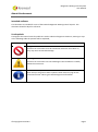
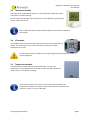
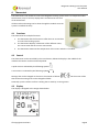
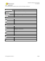
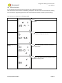
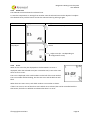
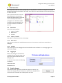
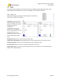
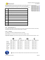
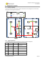
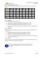
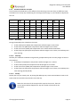
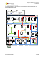
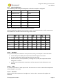
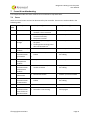
Biogenetic Heating Control System User Manual Release date: 02-10-2012 Version 1.0 Software Version 1.5 Revisions Version Author Date Changes 0.1 RiVer 25-09-2012 Initial release 1.0 RiVer; JeLob 02-10-2012 First released version Contents About this document............................................................................................................................... 1 Intended audience............................................................................................................................... 1 Used symbols....................................................................................................................................... 1 1 Introduction ..................................................................................................................................... 2 2 System description .......................................................................................................................... 4 3 4 2.1 Zones ....................................................................................................................................... 4 2.2 Biogenetic Heating-Panels....................................................................................................... 4 2.3 Operating modes ..................................................................................................................... 5 2.3.1 Scheduler mode............................................................................................................... 5 2.3.2 Manual mode .................................................................................................................. 5 2.3.3 Holiday mode .................................................................................................................. 5 System components ........................................................................................................................ 6 3.1 Controller................................................................................................................................. 6 3.2 CIB............................................................................................................................................ 6 3.3 Thermostat module ................................................................................................................. 7 3.4 I/O module .............................................................................................................................. 7 3.5 Temperature module .............................................................................................................. 7 Thermostat ...................................................................................................................................... 8 4.1 Functions ................................................................................................................................. 8 4.2 Control ..................................................................................................................................... 8 4.3 Display ..................................................................................................................................... 8 4.3.1 4.4 5 Display items ................................................................................................................... 9 Menu structure...................................................................................................................... 10 4.4.1 Actual temperature ....................................................................................................... 11 4.4.2 Date / Time .................................................................................................................... 13 4.4.3 Actual Temperature setting........................................................................................... 15 4.4.4 Holiday schedule ........................................................................................................... 18 4.4.5 Select zone..................................................................................................................... 19 4.4.6 Errors ............................................................................................................................. 19 Web interface ................................................................................................................................ 20 5.1 Overview................................................................................................................................ 20 5.1.1 Caption / Header ........................................................................................................... 20 5.1.2 Main menu .................................................................................................................... 20 5.1.3 6 5.2 Logging in............................................................................................................................... 20 5.3 Submit changes ..................................................................................................................... 20 5.4 Pages...................................................................................................................................... 22 5.4.1 Zone 1 - 6 ....................................................................................................................... 22 5.4.2 Thermostat Zone 1 - 6 ................................................................................................... 23 5.4.3 Info................................................................................................................................. 24 Configuration examples ................................................................................................................ 25 6.1 Domestic example ................................................................................................................. 25 6.1.1 Logical configuration ..................................................................................................... 25 6.1.2 Scheduler living room example ..................................................................................... 26 6.1.3 Scheduler bedroom example ........................................................................................ 27 6.2 7 Content .......................................................................................................................... 20 Industrial & Office example ................................................................................................... 28 6.2.1 Logical configuration ..................................................................................................... 29 6.2.2 Production facility / office environment example ........................................................ 29 6.2.3 Special zones/rooms...................................................................................................... 30 Errors & troubleshooting............................................................................................................... 31 7.1 Errors ..................................................................................................................................... 31 7.2 Connecting to the controller ................................................................................................. 32 7.2.1 Appendix A IP-address of the controller ........................................................................................... 32 Setting IP-address to connect to controller .................................................................. 33 Prerequisites...................................................................................................................................... 33 Determine the new IP-address of the computer .............................................................................. 33 Biogenetic Heating Control System User Manual About this document Intended audience This document is intended for users of the Kremsol Biogenetic Heating Control System. This document should be kept for reference. Used symbols Throughout the manual several symbols are used to indicate dangerous situations, warnings or tips. In the following table the symbols will be explained; Symbol Meaning Danger Functions or instructions must be carried out with care! If not done so, they may cause irreversible damage. Warning Functions or instructions can cause damage to the installation. Carefully follow the instructions. Informational or tip Hints and tips are given at these symbols. Some make carrying out the instructions easier. Others give some background information. © Copyright Kremsol B.V. Page 1 Biogenetic Heating Control System User Manual 1 Introduction This document describes the usage of the Kremsol Biogenetic Heating Control System. How the system is thought out and what the different terms mean is described in chapter 2 System description. Also the different heating operating modes are described here. The Kremsol Biogenetic Heating Control System consists of several components which will be described in Chapter 3 System components. To control the system for your living room or any other room the thermostat module is available. How to use it is described in chapter 4 Thermostat. The web interface used monitor the system and setup the modes is described in chapter 5 Web interface. There are two chapters with examples. These examples give an idea of the possibilities and configuration options. Chapter 0 © Copyright Kremsol B.V. Page 2 Biogenetic Heating Control System User Manual Configuration example gives an example of a two story family house while chapter 6.2 Industrial & Office example gives an example of a production hall and office combination. Last but not least chapter 7 Errors & troubleshooting where the possible errors and common troubleshooting is discussed. Appendix A contains a description how to setup the network interface of the computer to connect to the controller. © Copyright Kremsol B.V. Page 3 Biogenetic Heating Control System User Manual 2 System description The Kremsol Biogenetic Heating Control System is designed to comfortably heat 6 separate zones/rooms using Biogenetic Heating-panels. Each zone will be monitored separately and controlled separately. This makes it possible to set a different temperature for every room. 2.1 Zones A zone is a room or large part of a room for which an operating mode (see 2.3 Operating modes) can be selected. To make this possible the zone has to have a separate temperature measurement and Biogenetic Heating panel(s). 2.2 Biogenetic Heating-Panels The Biogenetic Heating panels generate Infrared-C waves. Infrared-C is naturally emitted by the sun. Their purpose is to heat our planet and they are totally harmless. The Biogenetic Heating panels can heat up to 6,5 meters with a wavelength of 10000 nm. The temperature of a zone is regulated by these panels. A zone can contain one or more panels, depending on the size, temperature gap and heat loss of a room. Generally a panel contains a PT1000 to measure the temperature of the panel. When a zone contains more than one panel, there is only 1 panel of which the temperature is measured by the system. This is called the master panel. Other panels in the same zone are assumed to have (almost) the same temperature. Every panel is equipped with a Clixon to prevent overheating in case of a failure. The panels can become hot! 180 °C ! © Copyright Kremsol B.V. Page 4 Biogenetic Heating Control System User Manual 2.3 Operating modes To facilitate different needs there are 3 different operating modes available for a zone. There is only one operating mode active per zone, at one time. The different operating modes are discussed below. 2.3.1 Scheduler mode The scheduler mode is active when the manual mode or holiday mode is not active. A schedule can be set using the clock thermostat. It allows to set the temperature for 4 different time periods over the day, for each weekday. The four periods are indicated by the following symbols: Wake up time Leave time Return time Sleep time For each period the time it becomes active and the desired temperature will be set. 2.3.2 Manual mode The manual mode allows to set one desired temperature per zone. The biogenetic heating system will try to maintain this temperature as long as the manual mode is active. The manual mode can be enabled and disabled by the user. 2.3.3 Holiday mode The holiday mode is nearly the same as the manual mode. Except that the holiday only become active when the scheduler mode is active. A temperature and a number of days is set. The set temperature is then maintained for the number of days set. Once the days are over the scheduler will become active again. © Copyright Kremsol B.V. Page 5 Biogenetic Heating Control System User Manual 3 System components The complete system consists of several components, which all have their specific task. In this chapter those components will be discussed. 3.1 Controller The controller used to control the heating. It gathers all the necessary information from the sensors and inputs. By combining the information from the sensors and the current active modes the outputs are activated. One controller supports 6 zones. When there are more than 6 zones to be controlled, an extra controller is necessary. 3.2 CIB CIB bus is the bus system over which the Kremsol Biogenetic Heating Control System communicates. It can communicate with modules specifically designed for the controller. © Copyright Kremsol B.V. Page 6 Biogenetic Heating Control System User Manual 3.3 Thermostat module The thermostat module allows the user to view information about the system and allows it to adjust settings. By turning the button pages can be selected or values adjusted. By pushing the button, values can be set. More information about the thermostat module can be found in chapter 4 Thermostat. 3.4 I/O module This module contains outputs to the panels and measures the temperature of panels. This information is sent to the controller to maintain the right temperature in a zone. Do not tamper with the module there is high voltage flowing through the module. It can be dangerous! 3.5 Temperature module The temperature module measures the temperature in a zone. The temperature is transmitted to the controller and the controller adjusts the output values to the panels according. Since the bus system is the same as for the thermostat modules, the temperature modules can easily be replaced by a thermostat when more comfort / control in a zone is desirable. © Copyright Kremsol B.V. Page 7 Biogenetic Heating Control System User Manual 4 Thermostat The thermostat is the module to control the Biogenetic heating system with. This chapter describes the functions, ways to control, display items and the menu structure of the thermostat. All the modes and settings can be done through this module once the system is installed correctly. 4.1 Functions The thermostat has multiple functions: 1. The thermostat has the function to offer the user an interface to control the heating system. 2. The thermostat displays information of the different zones, the current time and the current active mode. 3. The thermostat measures the temperature of the zone in which it is installed. 4.2 Control The thermostat can be controlled by the round button, below the display in the middle of the module. The button can be turned and pushed. A push action is indicated by the following symbol: A turn action is indicated by the following symbol: Settings that can be changed are shown in the manual as follows: thermostat the setting that can be changed will blink. On the screen of the Generally a push is used to confirm a setting that is made by a turning action. 4.3 Display The display is designed as the image shown below: © Copyright Kremsol B.V. Page 8 Biogenetic Heating Control System User Manual 4.3.1 Display items In the following table the display items and there meaning are displayed. Numbers and texts Days: Monday (1) to Sunday(7) 20.20 Temperature, date, time or setting 1..6 Zone number Current page is a setting Error in current zone Time periods Wake up time Leave time Return time Sleep time Icons Clock / Time Temperature Heating on in current zone Holiday mode Settings available Zone Alarm active in a zone Letters Auto mode (scheduler) Manual mode © Copyright Kremsol B.V. Page 9 Biogenetic Heating Control System User Manual 4.4 Menu structure For a graphical overview of the menu structure see the Quick Install Sheet. The main items are discussed in the following paragraphs. The main items can be browsed by turning the round button. By pressing the button the sub items become visible and often present settings. The main menu is shown in the following table: Information Display Action(s) Actual temperature Go to next (Date / Time) or previous (Select zone) item Date / Time Go to next (Actual temperature setting) or previous (Current temperature) item Actual temperature setting Go to next (Holiday schedule) or previous (Date / Time) item Holiday schedule Go to next (Select zone) or previous (Actual temperature setting) item © Copyright Kremsol B.V. Page 10 Biogenetic Heating Control System User Manual Select zone Go to next (Actual temperature) or previous (Holiday schedule) item 4.4.1 Actual temperature In the actual temperature item the actual temperature of the selected zone is shown. Beside the actual temperature it is possible to switch between auto and manual mode. 4.4.1.1 Auto mode (Scheduler) Information Display Current temperature Action(s) to Current set point 2 seconds to activate manual mode (see 4.4.1.2 Manual mode) Current set point Adjust current set point Adjust current set point confirm new set point and return to main menu Adjust active set point (10°C – 30°C) © Copyright Kremsol B.V. Page 11 Biogenetic Heating Control System User Manual 4.4.1.2 Manual mode Information Display Current temperature Action(s) to Current set point 2 seconds to activate auto mode (see 4.4.1.1 Auto mode (Scheduler) Current set point Adjust current set point Adjust current set point confirm new set point and return to main menu Adjust active set point (10°C – 30°C) © Copyright Kremsol B.V. Page 12 Biogenetic Heating Control System User Manual 4.4.2 Date / Time The Date / Time item shows the current time. Information Display Action(s) Actual time to Adjust year Adjust year Confirm year and go to Adjust month Adjust year (00 – 99) Adjust month Confirm month and go to Adjust day Adjust month (01 – 12) Adjust day Confirm day and go to Adjust hour Adjust day (01 – 28/29/30/31 depending on month and leap year) Adjust hour Confirm hour and go to Adjust minute Adjust hour (00 – 23) © Copyright Kremsol B.V. Page 13 Biogenetic Heating Control System User Manual Adjust minute Confirm minutes and return to main menu Adjust minute (00 – 59) © Copyright Kremsol B.V. Page 14 Biogenetic Heating Control System User Manual 4.4.3 Actual Temperature setting The actual temperature setting shows the current set point of the selected zone When pressing the button adjustment of the schedule (of the selected zone) is started. For each weekday the four periods are adjusted. Only one full day with four periods is shown in this manual. After the sleep temperature the next day is setup. Until all days (Monday to Sunday) are configured. Information Display Action(s) Current temperature set point to Start hour wake up period adjustment Start hour wake up period Confirm hour and go to Start minute wake up period (Monday – Sunday) Adjust wake up hour (00 – 23) Start minute wake up period Confirm minutes and go to Temperature of wake up period (Monday – Sunday) Adjust wake up minute (00 – 59) Temperature of wake up period Confirm selected temperature and go to Start hour of leave period (Monday – Sunday) Adjust wake up temperature set point (10°C – 30°C) © Copyright Kremsol B.V. Page 15 Biogenetic Heating Control System User Manual Start hour leave period Confirm hour and go to Start minute leave period (Monday – Sunday) Adjust leave hour (00 – 23) Start minute leave period Confirm minutes and go to Temperature of leave period (Monday – Sunday) Adjust leave minute (00 – 59) Temperature of leave period Confirm selected temperature and go to Start hour of return period (Monday – Sunday) Adjust leave temperature set point (10°C – 30°C) Start hour return period Confirm hour and go to Start minute return period (Monday – Sunday) Adjust return hour (00 – 23) Start minute return period Confirm minutes and go to Temperature of return period (Monday – Sunday) Adjust return minute (00 – 59) © Copyright Kremsol B.V. Page 16 Biogenetic Heating Control System User Manual Temperature of return period Confirm selected temperature and go to Start hour of return period (Monday – Sunday) Adjust return temperature set point (10°C – 30°C) Start hour sleep period Confirm hour and go to Start minute sleep period (Monday – Sunday) Adjust return hour (00 – 23) Start minute sleep period Confirm minutes and go to Temperature of sleep period (Monday – Sunday) Adjust return minute (00 – 59) Temperature of sleep period (Monday – Sunday) Confirm selected temperature and go to Start hour of wake up period next day OR Confirm selected temperature and return to main menu Adjust return temperature set point (10°C – 30°C) To exit the adjustment before all days and periods are set, press the button for 2 seconds and you will be returned to the main menu. © Copyright Kremsol B.V. Page 17 Biogenetic Heating Control System User Manual 4.4.4 Holiday schedule The holiday schedule shows the remaining days of the holiday. By pushing the button, first the number of holiday days is configured. By pushing again, the desired temperature is set. Information Display Action(s) Days of holiday remaining to Set number of days remaining Set number of days remaining Confirm days and go to Adjust temperature for holiday Adjust number of days (00 – 99) Adjust temperature for holiday Confirm selected temperature and return to main menu Adjust holiday temperature set point (10°C – 30°C) © Copyright Kremsol B.V. Page 18 Biogenetic Heating Control System User Manual 4.4.5 Select zone The selected zone item shows the selected zone. To view the temperature or settings from another zone the selected zone can be adjusted. To adjust the selected zones push the button and set the selected zone by pushing it again. Information Display Action(s) Current zone to Set zone to view/adjust Set zone to view/adjust Confirm selected zone and return to main menu Adjust zone (01 – 06 depending on configurations zones) 4.4.6 Errors When errors occur they are displayed on the thermostat. An error is displayed, when the selected zone (see 4.4.5 Select zone) is set to the zone when an error occurs. The error is displayed in the small numbers on the left of the zone number. The error number will be blinking, also the text error and the bell icon will blink. When there are more errors, each blink another error number is shown. If there’s an error on one of the other zone’s which not is selected, but can be controlled with the thermostat, the bell icon will blink to indicate that there’s an error. © Copyright Kremsol B.V. Page 19 Biogenetic Heating Control System User Manual 5 Web interface This chapter describes the steps (a paragraph per step) which are needed to configure the Kremsol Biogenetic Heating Control System. The steps are in order for a new install but can be read separately for later reference. Open your web browser and enter the IP-address of the controller. Default 192.168.134.176. To be sure use the technique described in paragraph 7.2.1 IP-address of the controller. See also Appendix A to set-up the network controller of your PC. 5.1 Overview Parts of the web interface. 1. Caption / Header 2. Main menu 3. Content 5.1.1 Caption / Header The caption / header shows the current page. 5.1.2 Main menu The main menu shows the available menu items to the current user. Each menu item links to a webpage. 5.1.3 Content The content part of the webpage shows the selected content. Whether it is a settings page or an informational page. 5.2 Logging in Before any settings or information is available the user needs to login. The login screen will look like the one on the right side. To start the setup enter the following credentials: Username: Lexin Password: Lexin 5.3 Submit changes The Submit button is generally available on pages with settings. To submit the changes click on the button or press enter. Changes which not active in the controller are visible by their red color. © Copyright Kremsol B.V. Page 20 Biogenetic Heating Control System User Manual © Copyright Kremsol B.V. Page 21 Biogenetic Heating Control System User Manual 5.4 Pages Per page or group of pages the information shown and available settings will be discussed. Some pages might not be available when you are not logged in with the right credentials. 5.4.1 Zone 1 - 6 The Zone 1-6 pages are purely informational pages. The following information is shown on the pages: Zone name: Above the zone and panel gauges the name of the zone is shown. This can be changed in the zones configuration. Temperature zone gauge: Shows a gauge with the current temperature of the zone. Temperature zone: Shows the current temperature of the zone. Set point zone: Shows the current set point of the zone. Temperature panel gauge: Show a gauge with the current temperature of the reference panel. Temperature panel: Shows the current temperature of the reference panel. Set point panel: Shows the current set point of the panels in the zone. Zone outputs: Shows the current activated output of the zones. Output 1 is for multiplex group 0, Output 2 for multiplex group 1 © Copyright Kremsol B.V. Page 22 Biogenetic Heating Control System User Manual Error list: Beside the Zone and panel information an error list is shown this list shows all of the current active errors in red. A list of all available alarms is shown below (for more details see 7 Errors & troubleshooting). Error Description 1 Pt1000 panel - Short circuit 2 Pt1000 panel - Wire break 3 No change of panel temperature 4 C-OR-0202B General Error 5 C-OR-0202B Communication Error 6 C-IT-0200R General Error 7 C-OR-0202B Communication Error 8 RCM2-1 General Error 9 RCM2-1 Communication Error 5.4.2 Thermostat Zone 1 - 6 On the thermostat pages, multiple settings can be made. The details of the scheduler can be setup, the holiday mode can be set and the manual mode is available. 5.4.2.1 Scheduler For Monday to Sunday the following settings are available: Time columns: For each period the start time can be set(0:00 - 23:59). Temperature columns: Per period the temperature that will be maintained can be set(10°C - 30°C). Sleep time must be always before 23:59 and after the time of the last period. © Copyright Kremsol B.V. Page 23 Biogenetic Heating Control System User Manual 5.4.2.2 Holiday mode The holiday mode has two settings. (remaining) Days: The days the Holiday mode is active(0-99). After these days the scheduler becomes active again. Temperature: The temperature that during the holiday mode is maintained in this zone(10°C – 30°C). The holiday mode must be set for each separate zone. 5.4.2.3 Manual mode By disabling the schedule mode, the manual mode becomes active. For the manual mode a fixed temperature is set. Schedule active: If the checkbox is empty, the manual mode is active, otherwise the schedule mode is active. Constant temperature: The temperature that will be maintained when the manual mode is active(10°C – 30°C). 5.4.3 Info The info page shows information about firmware and software versions. Also the information about the customer is shown. © Copyright Kremsol B.V. Page 24 Biogenetic Heating Control System User Manual 6 Configuration examples 6.1 Domestic example A two story family house with 6 zones is used for clarification of the configuration. On the left side, the first floor, on the right the second floor. Legenda Heating panel Controller Thermostat Temp. sensor Zone Zone Nr. I/O block 3 CIB Bus Power supply PT1000 900mm 2 1 4 3 5 6 6.1.1 Logical configuration In the following table the logical configuration as how the example is configured. Zone Room # of panels Temp. Measurement 1 Living room 2 Thermostat 2 Kitchen 1 Sensor 3 Hallway 1 Sensor 4 Bedroom 1 2 Sensor 5 Bedroom 2 1 Sensor 6 Bathroom 1 Sensor © Copyright Kremsol B.V. Page 25 Biogenetic Heating Control System User Manual 6.1.2 Scheduler living room example For the living room of the two story family house an example schedule is made. It is shown here below. Day Temp. Temp. Temp. Temp. Monday 06:30 17 10:00 18 18:00 20 22:00 15 Tuesday 06:30 17 10:00 18 18:00 20 22:00 15 Wednesday 06:30 17 10:00 18 18:00 20 22:00 15 Thursday 06:30 17 10:00 18 18:00 20 22:00 15 Friday 06:30 17 10:00 18 18:00 20 22:00 15 Saturday 08:00 17 09:30 18 18:00 20 23:00 15 Sunday 09:00 20 09:00 20 09:00 20 22:30 15 6.1.2.1 Weekdays During the weekdays the schedule is the same. At the wakeup time (06:30) the temperature will be brought to 17° Celsius. At the leave time (10:00) the temperature will be brought to 18° Celsius. At the return time (18:00) the temperature will be brought to 20° Celsius. At the sleep time (22:00) the temperature will be brought to 15° Celsius, until wakeup time next morning. 6.1.2.2 Saturday Saturday has a different schedule since generally, people wake up later and stay longer at home in the weekend. At wakeup time (08:00) the temperature will be brought to 17° Celsius. At leave time (09:30) the temperature will be brought to 18° Celsius. At the return time (18:00) the temperature will be brought to 20° Celsius. At the sleep time (23:00) the temperature will be brought to 15° Celsius, until wakeup time next morning (Sunday 09:00). 6.1.2.3 Sunday Sunday has only one switch point. By setting the Wakeup time, Leave time and Return time to the same value the controller only switches once that day. When the start time of the next period is equal to the current, then the current period will be skipped. This way the number of periods can be decreased. © Copyright Kremsol B.V. Page 26 Biogenetic Heating Control System User Manual 6.1.3 Scheduler bedroom example The schedule of the bedroom can be different from the living room since they are different zones. The bedroom is mostly only used during the mornings and evenings so, the schedule is adjusted to this use. Day Temp. Temp. Temp. Temp. Monday 06:30 18 08:00 15 20:00 15 22:00 18 Tuesday 06:30 18 08:00 15 20:00 15 22:00 18 Wednesday 06:30 18 08:00 15 20:00 15 22:00 18 Thursday 06:30 18 08:00 15 20:00 15 22:00 18 Friday 06:30 18 08:00 15 21:00 15 22:00 18 Saturday 08:00 18 09:30 18 18:00 20 23:00 18 Sunday 09:00 19 09:00 20 09:00 20 22:30 18 6.1.3.1 Weekdays During the weekdays the schedule is the same. At the wakeup time (06:30) the temperature will be brought to 18° Celsius. At the leave time (08:00) the temperature will be brought to 15° Celsius. At the return time (20:00) the temperature of 15° Celsius will be maintained. At the sleep time (22:00) the temperature will be brought to 15° Celsius, until wakeup time next morning. 6.1.3.2 Saturday Saturday has a different schedule since generally, people wake up later and stay longer at home in the weekend. At wakeup time (08:00) the temperature will be brought to 17° Celsius. At leave time (09:30) the temperature will be brought to 18° Celsius. At the return time (18:00) the temperature will be brought to 20° Celsius. At the sleep time (23:00) the temperature will be brought to 15° Celsius, until wakeup time next morning (Sunday 09:00). 6.1.3.3 Sunday Sunday has only one switch point. By setting the Wakeup time, Leave time and Return time to the same value the controller only switches once that day. When the start time of the next period is equal to the current, then the current period will be skipped. This way the number of periods can be decreased. © Copyright Kremsol B.V. Page 27 Biogenetic Heating Control System User Manual 6.2 Industrial & Office example The following layout will be used to clarify the use of the Biogenetic heating control system in an office and industrial environment. Legenda Heating panel Controller Thermostat Temp. sensor Zone Zone Nr. I/O block 3 Power supply PT1000 CIB Bus 1 5 2 6 3 4 © Copyright Kremsol B.V. Page 28 Biogenetic Heating Control System User Manual 6.2.1 Logical configuration In the following table the logical configuration as how the example is configured. Zone Room # of panels Temp. Measurement 1 Production room 4 Sensor 2 Assembly room 8 Sensor 3 Hallway 2 Sensor 4 Main Office 2 Thermostat 5 Assembly office 1 Thermostat 6 Meeting room 1 Thermostat 6.2.2 Production facility / office environment example When the Biogenetic Heating Control System is used in a production facility or office environment the scheduler can be used to switch according to those times. Day Temp. Temp. Temp. Temp. Monday 08:00 20 08:00 20 17:00 15 22:00 15 Tuesday 08:00 20 08:00 20 17:00 15 22:00 15 Wednesday 08:00 20 08:00 20 17:00 15 22:00 15 Thursday 08:00 20 08:00 20 17:00 15 22:00 15 Friday 08:00 20 08:00 20 12:30 15 22:00 15 Saturday 08:00 15 08:00 15 08:00 15 22:00 15 Sunday 08:00 15 08:00 15 08:00 15 22:00 15 6.2.2.1 Weekdays During the weekdays the schedule is mostly the same, Friday, the exception is discussed below. At the wakeup time (08:00) the temperature will be brought to 20° Celsius. The same temperature will be maintained for the Leave time. At the return time, end of production / working hours (17:00) the temperature will be brought to 15° Celsius. At the sleep time (22:00) the temperature will be maintained, until wakeup time next morning. 6.2.2.2 Friday On Friday the production / work stops earlier. The return time is set to 12:30 and the temperature will be brought to 15° Celsius. 6.2.2.3 Weekend When on Friday the temperature is brought to 15° Celsius, this is maintained throughout the weekend. © Copyright Kremsol B.V. Page 29 Biogenetic Heating Control System User Manual 6.2.3 Special zones/rooms Sometimes there are zones or rooms which do not need an scheduler. In this example the meeting room is such. It is possible that the meeting room is not used every day or on irregular times. In that case, a low temperature can be set (manual) by default. When using the room the temperature can be set manually to a higher temperature. The thermostat in one room (thermostat of zone 4) can be used to set the temperature in another room. For the meeting room this can be useful to pre-heat the room. For adjustments the thermostat in the meeting room can be used. © Copyright Kremsol B.V. Page 30 Biogenetic Heating Control System User Manual 7 Errors & troubleshooting This chapter describes the most common errors and how to cope with them. 7.1 Errors Some errors are known and can be determined by the controller. These errors are described in the following table. Error Anomaly (Possible) cause(s) (Possible) solution(s) 1 Short circuit Contact your local installer 2 Wire break Contact your local installer 3 No temperature change The output on one of the I/O modules is short circuited One of the inputs is not connected correctly. The panel is broken. There is no power supplied to the panel The Biogenetic Heating-panel does not become hot I/O module broken Contact your local installer Contact your local installer The cable to the I/O module is broken Let your local installer check the cabling code 4 General error I/O module 5 No communication I/O module 6 General error Temperature module Temperature module broken Contact your local installer 7 No communication temperature module The cable to the temperature module is broken Let your local installer check the cabling 8 General error Thermostat Thermostat broken Contact your local installer 9 No communication to thermostat The cable to the thermostat is broken Let your local installer check the cabling H No communication over the bus to the thermostat The controller has an error Controller is not running Power the controller down and up again © Copyright Kremsol B.V. Page 31 Biogenetic Heating Control System User Manual 7.2 Connecting to the controller When the connection to the controller is not working several points need to be checked. They are described in this paragraph. Network connection available (physical): o Network cable attached to the computer and the controller o Network port on the controller shows a green led IP-address and subnet are in the same range as the controller. To find the IP-address see paragraph 7.2.1 IP-address of the controller. The network port is enabled in your operating system (Windows, Mac, Linux, etc.) 7.2.1 IP-address of the controller The IP-address of the controller can be found by pressing and hold the Mode button below the 8segment display. The display will show the IP-address character by character. The format will be as follows: Eth1-IP = <IP-Address> © Copyright Kremsol B.V. Page 32 Biogenetic Heating Control System User Manual Appendix A Setting IP-address to connect to controller To connect to the controller and be able to use the web interface the IP-address of the computer should be in the correct range. How to do this is explained in this appendix. Prerequisites The following prerequisites should be met before starting with setting the IP-address This appendix describes a method using Microsoft Windows 7. But other operating systems which are used for web browsing are possible as well. The computer has a physical connection to the controller, direct or through a switch or hub. o When there is a direct connection make sure that you are using a cross cable or make sure that the network adapter of the computer is self-switching. o When using a switch or hub make sure the ports the computer and controller are plugged into are allowed to communicate un-obstructed. Make sure you have administrator rights on the computer. Determine the new IP-address of the computer An IP-address is used to address a computer on a network. An IP-address looks as follows: 192.168.134.176. It has four octets separated by a dot. Before the IP address of the computer can be set, first the IP address of the controller has to be known. The IP-address of the controller can be found by pressing and hold the Mode button below the 8-segment display. The display will show the IP-address character by character. The format will be as follows: Eth1-IP = <IP-Address> The dots between the octets are replaced by a low dash (_). The IP-address (192.168.134.176) is the default for the controller and is used as an example. To be able to connect to the computer the first 3 octets of the IP-address of the controller are maintained (192.168.134). The last octet (176) should be changed so it is not the same as the controller. In this case we will use 150 as the last octet. The complete IP-address of the computer will be: 192.168.134.150 Setting IP-address in Windows Click on the start menu button in windows. Then click on Control Panel. © Copyright Kremsol B.V. Page 33 Biogenetic Heating Control System User Manual Then click on Network and Internet or Network and Sharing Center, depending on how the view is setup. Then click on the LAN-connection to open the status of that connection. In the status dialog click on the Properties button. In the properties dialog select the Internet Protocol Version 4 (TCP/IPv4) item. The click on the Properties button. Write down the current settings in the dialog shown. So you can return the settings to that state when the configuration is done! © Copyright Kremsol B.V. Page 34 Biogenetic Heating Control System User Manual Select Use the following IP address:. Then fill in the IP address as determined before. And the Subnet mask should be 255.255.255.0 as shown in the example. The other fields should be left empty. Press the OK button twice to close the two property dialogs. Then press the close button to close the last dialog. Then open a web browser like Internet Explorer, Google Chrome or Mozilla Firefox. Then enter the address of the controller in the address bar. Now the web interface of the controller is visible! © Copyright Kremsol B.V. Page 35