1
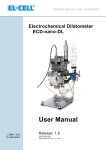
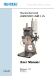
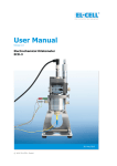
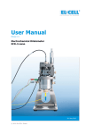
Electrochemical Dilatometer ECD-1 User Manual Serial-No © 2007 - 2012 EL-Cell GmbH Release: 2.2 2012-02-02 The information in this manual has been carefully checked and believed to be accurate; however, no responsibility is assumed for inaccuracies. EL-Cell GmbH maintains the right to make changes without further notice to products described in this manual to improve reliability, function, or design. EL-Cell GmbH does not assume any liability arising from the use or application of this product. EL-Cell GmbH - Tempowerkring 6 D-21079 Hamburg Germany phone:+49 (0)40 790 12 733 fax: +49 (0)40 790 12 736 [email protected] Page 2 of 39 ECD-1_manual 2012 02 02 / 02/02/2012 Contents 1 Product Description .................................................................................... 4 2 Technical Specifications .............................................................................. 5 3 Safety Precautions ...................................................................................... 6 4 Unpacking.................................................................................................. 6 5 ECD-1 Operation ........................................................................................ 8 5.1 Assembly ................................................................................................ 8 5.2 Connecting the Instrument .................................................................... 19 5.3 Recording the displacement signal with the data logger .......................... 21 5.4 Recording the displacement signal with the potentiostat (Optional) .......... 22 5.5 Sensor Sleeve Adjustment ..................................................................... 23 5.6 ECD-1 Disassembly ............................................................................... 24 5.7 Using the Reference Electrode ............................................................... 25 5.8 Using an Auxiliary Electrode ................................................................... 25 5.9 Changing the WE Load .......................................................................... 26 5.10 Using Single Crystals or Grains as the Working Electrode ......................... 27 5.11 Using Powder-Type Working Electrodes .................................................. 27 6 Accessories and Spare Parts ...................................................................... 28 7 Connector and Cable Pin-out ..................................................................... 35 8 Maintenance ............................................................................................ 37 9 Technical Support .................................................................................... 37 10 Appendix: AC Electrode Results ................................................................. 38 11 Warranty ................................................................................................. 39 Page 3 of 39 ECD-1_manual 2012 02 02 / 02/02/2012 1 Product Description The ECD-1 electrochemical dilatometer is dedicated to the measurement of chargeinduced strain (expansion and shrinkage) of electrodes down to the sub-micrometer range. The ECD-1 is particularly developed for the investigation of Li-ion battery and other insertion-type electrodes. It may, however, also be used for many other electrochemical systems utilizing organic as well as aqueous electrolyte solutions. The electrode materials used can either be bound films, single crystals (e.g. HOPG), or binder-free powders. The maximum electrode size is 10 mm x 1 mm (diameter x thickness). The heart of the ECD-1 is an electrochemical cell, hermetically tight against ambient atmosphere. The two electrodes inside are separated by a stiff glass frit that is fixed in position. The upper (working) electrode is sealed by means of a thin metal membrane, through which any charge-induced height change is transmitted towards the sensor/load unit above. This working principle allows determining the height change of the working electrode (WE) without any interference from that of the counter electrode (CE). A high-resolution displacement (LVDT) transducer detects dimensional changes of the WE ranging from 50 nanometers up to 500 micrometers, during one and the same experiment that may last between a few minutes to many days. A simple weight serves to adjust the load on the working electrode. For best accuracy and drift stability, we recommend operating the ECD-1 inside a temperature controlled chamber. This manual covers the ECD-1 Standard version together with the optionally available re-fitting kit for aqueous electrolytes. Page 4 of 39 ECD-1_manual 2012 02 02 / 02/02/2012 Friction-free flexure guide Exchangeable weight to control load on WE Sensor plunger Spacer disc for height adjustment Metal membrane Valve assembly for vacuum filling via syringe Auxiliary port Reference electrode assembly Gas filled dead volume to suppress changes in hydrostatic pressure inside cell Glass T-frit separates WE test specimen on top from CE below Spring-loaded CE plunger 2 Technical Specifications Page 5 of 39 LVDT sensor with two signal outputs, +2 to +10 V and -10 to +10V, and selectable gain. Signal conditioning for connection to a data logger and / or to the analog input channels of the controlling potentiostat / battery tester. Measurement range of ±500 µm Resolution of < 50 nm Drift stability of < 100 nm/hour (sample-free instrument at constant temperature) Sample (working electrode): bound film, binder-free powder, or single crystal / grain max. sample size 10 mm x 1 mm (diameter x thickness) Load on working electrode: 0.3 N or 1.3 N Electrolyte volume: <3 ml Materials in contact with electrolyte: PEEK, borosilicate glass, EPDM rubber and stainless steel 316L for aprotic, gold for aqueous electrolytes Operating temperature range Cell and Sensor: -20 to +70 °C Controller and Data Acquisition System: 0 to +40 °C ECD-1_manual 2012 02 02 / 02/02/2012 Minimum dimensions for glove box ante-chamber transfer (stand detached) Dimensions (ECD-1 completely assembled on stand) 3 Safety Precautions Use proper safety precautions when using hazardous electrolytes. Wear protective glasses and gloves to protect you against electrolyte that may accidentally spill out of the instrument during filling, operation, and disassembly. 4 Unpacking Check the contents of the packages against the list given below to verify that you have received all of the components. Contact the factory if anything is missing or damaged. NOTE: Damaged shipments must remain with the original packaging for freight company inspection. Page 6 of 39 ECD-1_manual 2012 02 02 / 02/02/2012 List of Components (Standard Version) 1. ECD-1 dilatometer (in the assembled state, equipped for use with aprotic electrolytes) 2. 3. 4. 5. Signal conditioning electronics (controller box) with DC power supply Cell cable Sensor Cable Data logger cable 6. Agilent 34972A Data Acquisition System (“Data Logger”) with 34901A 20 channel multiplexer board, 34825A Benchlink Data Logger Software, and documentation/drivers on CD 7. 8. 9. 10. 11. 12. 20 ml syringe with polysiloxane sealing Vacuum pipette and tweezers for electrode handling Hex wrenches for assembly and maintenance 3 tubing assemblies for interconnection between cell, valves and syringe Activated carbon electrode set (5 pcs) for reference measurements Re-fitting kit for aqueous electrolytes (to be ordered separately) Page 7 of 39 ECD-1_manual 2012 02 02 / 02/02/2012 5 ECD-1 Operation 5.1 Assembly The following photographs refer to the use of the dilatometer with aqueous electrolytes. For aprotic organic electrolytes, the assembly differs slightly as indicated in the respective figure captions. 1 Insert o-rings into cell body (21.95 x 1.78 and 41 x 1.78) 2 Insert glass frit (T frit 10/20 mm dia) into cell body Page 8 of 39 ECD-1_manual 2012 02 02 / 02/02/2012 3 Place CE (dia <= 20 mm) with the active layer downside on top of the glass frit 4 Place current collector disc on top of the CE NOTE: For aprotic organic electrolytes, this disc is not required. 5 Insert the central CE piston into the cell bottom (O-ring size 9.75 x 1.78 mm) NOTE: For aprotic organic electrolytes, use the stainless steel piston instead. Page 9 of 39 ECD-1_manual 2012 02 02 / 02/02/2012 6 Stack cell bottom (with central CE piston inserted) on top 7 Put base flange (with valve support attached) on top, hold the assembly tightly together, and turn it around 8 Screw the assembly together by means of the 3 hex socket screws M4x25 Page 10 of 39 ECD-1_manual 2012 02 02 / 02/02/2012 9 Attach the cell to the bracket, and fasten it with the two knurled screws 10 Screw in the CE spring load from below to its uppermost position, then release it slightly by turning the screw back (ccw) by 10 to 30 degrees. 11 Put the WE on top of the glass frit with the active layer downside. Page 11 of 39 ECD-1_manual 2012 02 02 / 02/02/2012 12 Place the spacer disc on top of the WE (gold for aqueous, stainless steel 316L for aprotic electrolytes). NOTE: By using the 2.1 mm thick spacer disc the neutral (flat) position of the membrane corresponds to an initial working electrode thickness of 250 µm (see sketch). Height changes between -250 and +250 µm relative to the neutral position are acceptable, without causing excessive bending of the membrane. WE Spacer disc Metal membrane T-frit CE Page 12 of 39 ECD-1_manual 2012 02 02 / 02/02/2012 13 Insert the membrane O-ring seal (33.05x1.78) 14 Insert the membrane (gold for aqueous, stainless steel 316L for organic aprotic electrolytes) 15 Place the cover flange on top Page 13 of 39 ECD-1_manual 2012 02 02 / 02/02/2012 16 Fasten the cover flange by means of the 3 hex socket screws M4x30. 17 Interconnect cell, valves and tubings as indicated by the numbering on the parts. 18 Close the side opening with the provided plug. NOTE: Optionally, this plug may be replaced by an auxiliary electrode. Page 14 of 39 ECD-1_manual 2012 02 02 / 02/02/2012 19 Attach the reference electrode (gold reference pin for aqueous, SS pin for aprotic electrolytes). NOTE: The reference pin is to be loaded with the appropriate reference electrode material. Dead volume valve (red) 20 Syringe valve (yellow) Fill the cell with electrolyte according to the following procedure 1. Charge a 20 ml syringe with ca. 3 ml of electrolyte. We recommend one-time use PP plastic syringes with low friction polysiloxane pistons. 2. Connect the syringe to the Luer adapter of the inner (syringe) valve 3. Open the syringe valve, and close the outer (dead volume) valve 4. Pull the syringe piston back to evacuate the cell. Hold the piston a few seconds in the strained position. 5. Release the piston so that the electrolyte is drawn into the cell. 6. Repeat the two previous steps to complete filling. 7. Close the syringe valve, and open the dead volume valve NOTE: The cell is now filled and hermetically tight. Up to this point, for airsensitive systems, assembly and filling has to be done in a glove box. All subsequent steps may be carried out in ambient atmosphere. Page 15 of 39 ECD-1_manual 2012 02 02 / 02/02/2012 21 Attach the sensor/load unit to the cell with the flexure guide locked in its upper position. 22 Fasten the sensor/load unit by means of the 3 hex socket screws M4x10. Page 16 of 39 ECD-1_manual 2012 02 02 / 02/02/2012 23 Unlock the flexure guide to lower the sensor tip down to the membrane. 24 Release the sensor plunger and fix it again. By doing so, the bias load resulting from the flexure deflection is reset to zero. Page 17 of 39 ECD-1_manual 2012 02 02 / 02/02/2012 Sensor Cable WE REF CE 25 Connect the instrument via the cell and sensor cables to the controller box. Page 18 of 39 ECD-1_manual 2012 02 02 / 02/02/2012 5.2 Connecting the Instrument 1. Place the ECD-1 inside a temperature controlled chamber, at a constant temperature between -20 to +70°C. 2. Establish all electrical connections between dilatometer, controller, and data logger according to the diagram given above. 3. Connect your potentiostat or battery tester to the 4 mm jacks on the front panel of the controller box. Refer to the table given below. Controller Box I2 REF I1 V1 Page 19 of 39 Potentiostat CE REF WE Current WE Sense ECD-1_manual 2012 02 02 / 02/02/2012 4. Connect the 2mm banana plugs of the cell cable to the dilatometer cell. Refer to the photo on page 19. The displacement signal can be recorded via the data logger, or, if available, by an analog input of the potentiostat that is used for charging the electrochemical cell. It is also possible to record the displacement signal simultaneously on both the data logger and the potentiostat. Two analog signals are provided, one in the range +2 to +10V, the other one in the extended range -10 to +10V. V1 is only available at the Sub-D data logger connector. It has a fixed bandwidth of 300 Hz (-3 dB) and a fixed gain of h/V1 = 0.00012025 m/V = 120.25 µm/V (S/N ...; calibration date ...) The gain and bandwidth of V2 are selectable by the DIP switches at the controller box. Gain h/V2 48.1 µm/V h/V1 x 2.5 Switch 1 Switch 2 ON ON ON OFF h/V1 x 5 24.05 µm/V OFF OFF h/V1 x 10 12.025 µm/V Switch 3 ON OFF Switch 4 OFF ON Bandwith V2 (-3 dB) 300 Hz 10 Hz The bar graph LED display at the controller box refers to the second displacement signal V2 at the actually chosen gain. The center of the bar graph display corresponds to an analog output signal V2 of around 0V, the outermost red LEDs indicate that V2 is outside the valid range of -10 to +10V. The signal V2 is available to the data logger / potentiostat via the Sub-D data logger connector, and at the BNC connector. Page 20 of 39 ECD-1_manual 2012 02 02 / 02/02/2012 5.3 Recording the displacement signal with the data logger The standard version of the ECD-1 comes with the Agilent 34970A data logger and the associated Benchlink software application. The data logger has to be configured to record the displacement signal along with the cell current, the electrode potentials, and the temperature inside the chamber. Set up the data logger’s channel list according to the screenshot given above. For software installation and data logger operation refer to the separate instructions coming along with the data logger. For best precision, set the resolution of channels 101, 102 and 107/117 to 6.5 digits (10 NPLC). Notice the impact of the resolution chosen and the number of channels activated on the maximum scanning speed of the data logger. At optimum precision and when all channels in the scan list are check marked, the scanning speed is limited to approximately 0.5 Hz (2 seconds each scan). Channel 102/902: To record the cell current, the voltage drop across a 100 Ohm resistor looped into the CE supply line is fed to channel 102. The 100 Ohm (1 Watt, 1%) resistor is located inside the controller box and is protected against overload by a 100 mA fuse. Both the resistor and the fuse can be replaced as necessary. For convenience, add two computed channels to the data logger’s scan list in order to directly display the electrode displacement in meters and the cell current in Amperes. Refer to the two computed channels at the bottom of the scan list shown above. Page 21 of 39 ECD-1_manual 2012 02 02 / 02/02/2012 Channels 107/117: These two channels are configured to measure the temperature by means of a 4-wire Pt100 sensor that is located inside the cell cable terminal close to the dilatometer. 5.4 Recording the displacement signal with a potentiostat (optional) Many battery testers and potentiostats provide additional analog input channels that may be used to record the displacement signal along with cell current and potential. In the following, connection of the ECD-1 to the Biologic VMP3 is described. Adaption to many other potentiostats is possible as well. I. Connect the 9-pin Sub-D connector of the data logger cable to the analog input of the respective VMP3 channel. II. Edit the cell characteristics settings of the VMP3 channel so as to record either one or both of the two analog inputs. Analog IN1 is connected to the displacement signal V1 with fixed gain, Analog IN2 to the displacement signal V2 with variable gain. Screenshot from the Biologic EC-Lab Software showing the analog input configuration Page 22 of 39 ECD-1_manual 2012 02 02 / 02/02/2012 NOTE: Before starting the electrochemical cycle we recommend holding the cell at open-circuit for several hours to allow for baseline stabilization. Following this procedure helps to discern charging induced dimensional changes from creeping. Note that all materials display a more or less pronounced creeping. They tend to shrink after applying a load, and to swell when removing this load. Creeping of the working electrode is initially induced when applying the load. It is also induced each time the mechanical properties of the working electrode are significantly altered by charging. Therefore, each charging induced height change is followed by some creeping. Both the initial and the charging induced creeping effects are real and not artefacts of the measurement. 5.5 Sensor Sleeve Adjustment For optimal utilization of the displacement range, for very thick samples or for samples showing large expansion, it may be advantageous to alter the mechanical null position of the sensor. This is to be done on the fully assembled instrument. Release the hex socket screw (1), and move the sensor sleeve (2) vertically into the desired position. Significant force is to be applied to move / turn the sleeve. The corresponding sensor signal on channel 101 must be between 2 and 10 V, referring to the upmost and lowermost valid position of the sensor sleeve. Fix the sleeve at a sensor voltage of about 6 V to start the measurement at mid-range. Note: The valid adjustment range is about ±0.5 mm relative to the default position of the sensor sleeve. Outside this range, the sensor signal is no longer linearly related to displacement. The sleeve may be lowered by approximately 5 mm before collision with the plunger (core) inside. Avoid collision in any case. (2) (1) Page 23 of 39 ECD-1_manual 2012 02 02 / 02/02/2012 5.6 ECD-1 Disassembly 1. Open the potentiostat’s charging-circuit and unplug the power supply from the controller box. Disconnect all cables from the dilatometer. Then remove the instrument from the temperature chamber. 2. Lock the flexure guide in the upper position by moving the adjustment wedge into the leftmost position. 3. Detach the sensor/load unit. 4. Remove the plug from the cell body, and open the syringe valve. Then draw any free electrolyte back into the syringe, and close the syringe valve. 5. Detach the reference electrode 6. Disconnect all tubings from the valves and from the cell. 7. Remove the cover flange, the metal membrane, the spacer disc, and the working electrode. NOTE: The membrane may be re-used many times. A slight bending and a tiny dent in the center of the membrane are normal signs of use. 8. Unscrew the counter electrode spring load. 9. Detach the remaining cell from the bracket. 10. Unfasten the cell body, and remove the T-frit from the cell body. NOTE: Take care not to jam or break the frit. The frit may accidentally slip out of the cell body. 11. Clean all parts that have been in contact with electrolyte. Depending on the electrolyte and electrodes used, the wetted parts may be cleaned with water, dilute detergent wash, ethanol or acetone. Ultrasonic cleaning is recommended. Dry all parts immediately after cleaning in vacuum at 80°C overnight. It is highly recommended to additionally dry cell body and cell bottom in vacuum at 150°C overnight. Absorbed moisture may otherwise adversely affect test results. Check O-ring seals and the T-frit visually for damage and replace as necessary. Page 24 of 39 ECD-1_manual 2012 02 02 / 02/02/2012 5.7 Using the Reference Electrode The reference electrode assembly is comprised of the reference pin (1), the set collar (2) attached to the pin by means of a set screw (3), the fitting (6), the spring (4), and the hollow screw (5), cf. the sketch below. The hollow screw serves to apply the spring pressure on the set collar, thereby gently pushing the reference pin against the glass frit. The blind bore on the tip of the reference pin is intended for taking up the reference electrode material. For most lithium ion chemistries the reference material may be a small piece of lithium metal picked up by the reference pin. For other aprotic electrolytes, and also for some aqueous systems, a piece of PTFE bound activated carbon may serve as the (pseudo) reference material. The optional gold reference pin is recommended for use in aqueous electrolytes. NOTE: Do not use the gold reference pin in combination with lithium metal. 5.8 Using an Auxiliary Electrode As an option, the ECD-1 may be equipped with an additional electrode face to face with the reference electrode. This auxiliary electrode may be a second reference electrode, or simply a bare metal wire. For instance, in aqueous solutions, a platinum wire auxiliary electrode may be cycled against the counter electrode to determine the actual electrode potential of a simultaneously attached pseudo reference electrode. The auxiliary electrode assembly is virtually identical with the reference electrode assembly, except that the reference pin is replaced by a metal wire with 1.5 mm diameter. Page 25 of 39 ECD-1_manual 2012 02 02 / 02/02/2012 5.9 Changing the WE Load By default, the sensor/load unit is equipped with a weight (appr. 100 g) to assure a good electrical contact between the working electrode and the membrane over the whole displacement range. In some situations, however, it may be preferable to apply only the dead load of the sensor plunger and the flexure (ca. 30 g in the neutral position). To remove the 100 g weight, follow the instructions given below. 1. 2. 3. 4. 5. 6. 7. 8. Detach the sensor/load unit from the dilatometer cell Release the knurled screw (1) Pull out the sensor plunger (4) with the weight (2) attached on it Release the set screw of the weight with the provided hex-wrench (3), and remove the weight Insert the plunger (4) into the leftmost position, and fasten the knurled screw (1) Attach the sensor/load unit back to the cell Unlock the flexure guide Release the knurled screw, and re-fasten it (thereby moving the flexure guide in its neutral position. Make sure that the sensor tip (5) is sitting on the membrane. Knurled Screw (1) Weight (2) Hex Wrench (3) Sensor Plunger (4) Sensor Tip (5) Page 26 of 39 ECD-1_manual 2012 02 02 / 02/02/2012 5.10 Using Single Crystals or Grains as the Working Electrode As an option, the ECD-1 may be loaded with a single crystal or grain as the working electrode. For this purpose, the ball tip of the sensor/load unit is to be replaced by a flat tip, and the membrane is directly placed on top of the crystal, without the spacer disc in between. More detailed instructions come with the optionally available Part Kit for Single Crystals. 5.11 Using Powder-Type Working Electrodes The ECD-1 is also capable of using binder-free powders as the working electrode. Simply place a separator on top of the glass frit (to prevent contamination of the frit), and subsequently a small amount of the powder, appr. 5 to 15 mg. Just as for the measurements of single grains, cover the sample directly with the metal membrane, and use the sensor/load unit equipped with the flat tip (Part kit for Single Crystals). Filling the cell by the syringe/ vacuum technique prevents that loose powder is flushed away during the filling procedure. NOTE: Make sure that the sample has sufficient electronic conductivity, and that the contact resistance between sample and membrane is tolerable. An additional interlayer (e.g. gold foil for aqueous, carbon coated aluminium or copper foil for aprotic electrolytes) between sample and membrane may reduce the contact resistance drastically. Page 27 of 39 ECD-1_manual 2012 02 02 / 02/02/2012 6 Accessories and Spare Parts Page 28 of 39 ECC1-00-0019-C membrane (aprotic) stainless steel 316L ECC1-00-0019-A membrane (aqueous) gold ECD1-00-0014-A Part Kit "Sealings" ECC1-00-0041-A T-Frit (20/10) ECD1-00-0018-A Part Kit for single crystal WE ECD1-00-0008-B CE Spring Load II Duran sinter glass (poros. 3) ECD1-00-0005-B Central CE Piston II ECD1-00-0006-B Central CE Piston II (aqueous) PEEK/1.4305/ gold ECC1-00-0033-A Current Collector gold ECD1-00-0013-A Part Kit "Flexure Unit" ECD1-00-0015-A Part Kit "Screws" ECD1-00-0017-B Part Kit "Springs" II ECD1-00-0016-A Part Kit "Tubings" ECD1-00-0010-B Reference Electrode (aqueous) UNF1/4"-28 gold ECD1-00-0009-B Reference Electrode (aprotic) UNF1/4"-28 1.4430 ECC1-00-0018-B 2 mm spacer disk (aprotic) stainless steel 316L ECC1-00-0018-A 2 mm spacer disk (aqueous) gold ECD1-00-0020-A Terminal board with 2nd Data Logger Cable ECD-1_manual 2012 02 02 / 02/02/2012 (aprotic) 1.4404 Page 29 of 39 ECD-1_manual 2012 02 02 / 02/02/2012 Page 30 of 39 ECD-1_manual 2012 02 02 / 02/02/2012 Page 31 of 39 ECD-1_manual 2012 02 02 / 02/02/2012 Page 32 of 39 ECD-1_manual 2012 02 02 / 02/02/2012 Page 33 of 39 ECD-1_manual 2012 02 02 / 02/02/2012 Page 34 of 39 ECD-1_manual 2012 02 02 / 02/02/2012 7 Connector and Cable Pin-out Cell Cable (8 x 2 TP, shielded) One end of the cable is terminated with a Sub-D HD M15 connector (to box); the other end is terminated with 2 mm banana connectors (to ECD-1 cell). Pin # 1 2 3 4 5 6 7 8 9 10 11 12 13 14 15 Signal V1 V2 Cable Color Red Blue Color of 2mm Connector red blue REF I2 AUX Grey Yellow Pink black yellow black +5V white/blue I1 Pt100(1) Pt100(2) Pt100(3) Pt100(4) Green Violet Black White Brown green (R1) (R2) (R2) (R1) Data Logger Cable (8x2 TP, shielded) One end of the cable is terminated by a Sub-D HD F15 connector (to box); the other end is terminated by the multiplexer card of the data logger. Pin # 1 2 3 4 5 6 7 8 9 10 11 12 13 14 15 Page 35 of 39 Signal V1 V2 RA REF Sensor Signal 1 AUX RB Cable Color Red Blue brown/green grey green pink White/green Logger Channel #3HI, #4HI #3LO, #5HI #2LO #4LO, #5LO, #6LO #1HI #6HI #2HI AGND Pt100(1) Pt100(2) Pt100(3) Pt100(4) Sensor Signal 2 yellow violet black white brown white/yellow #1LO, #8LO #7LO #7HI #17LO #17HI #8HI ECD-1_manual 2012 02 02 / 02/02/2012 Analog Output Cable (4x1, shielded) Optionally, the datalogger cable is split into a second cable that is terminated with a Sub-D M9 connector. This connector fits directly into the auxiliary input connector of the Biologic VMP3 potentiostat. Adaption to other second-party instrumentation is available on request. Pin # 1 2 3 4 5 6 7 8 9 Signal Sensor Signal V1 Sensor Signal V2 GND - Cable Color green VMP3 AUX connector Analog IN1 white brown Analog IN2 GND Sensor Cable SUB-D F15 to box Round connector to sensor Pin # 1 2 3 4 5 6 7 8 9 10 11 12 13 14 15 Page 36 of 39 Signal secondary + secondary secondary mid primary primary + - Cable Color white brown grey blue black - ECD-1_manual 2012 02 02 / 02/02/2012 8 Maintenance Right after finishing an experiment, disassemble the instrument, dispose the electrodes, and clean all parts that have been in contact with electrolyte. Depending on the electrolyte and electrodes used, the wetted parts may be cleaned with water, dilute detergent wash, ethanol or acetone. Ultrasonic cleaning is recommended. Tubes and valves are to be purged with the aid of a syringe. Right after cleaning, all parts have to be dried in vacuum at max. 80°C. Check O-ring seals and the T-frit visually for damage and replace as necessary. 9 Technical Support Technical support for this product is exclusively handled by EL-Cell GmbH. The following procedure must be followed when the ECD-1 or any part of it is returned to EL-Cell GmbH for repair: 1. 2. 3. 4. 5. Send an e-mail to [email protected] to obtain a return authorization number and a decontamination report form. Sign the decontamination report asserting that the instrument has been decontaminated and is safe for technicians to work on it. Describe in detail what is wrong. Include a contact name, address, telephone number, and email address. Return the instrument to EL-Cell GmbH Tempowerkring 6 D-21079 Hamburg Germany Email [email protected] Page 37 of 39 ECD-1_manual 2012 02 02 / 02/02/2012 10 Appendix: AC Electrode Results The ECD-1 comes with a set of activated carbon (AC) double layer electrodes, 0.2mm thick and 9 mm in diameter. These electrodes may be used to get quickly familiar with the test procedure. The electrodes contain 75 wt-% of a mesoporous activated carbon with 1200 m2/g surface area (BET), and 25% of PTFE as a binder. The following diagrams show the dilatometric response of this electrode material during the first 10 cycles in 1.2M LiPF6 in EC/EMC 3:7 with a scan rate of 5 mV/s between 3.0 and 1.5V vs. Li/Li+. Lithium metal was used as both the counter and the reference electrode. Similar results are obtained with other common Li-ion battery electrolytes. 40 35 Height / µm 30 25 1 µm 20 15 10 400 sec 5 + ELi/Li / V I / mA 0 1 0 -1 3.0 2.5 2.0 1.5 0 2000 4000 Time / s Page 38 of 39 ECD-1_manual 2012 02 02 / 02/02/2012 6000 8000 11 Warranty For a period of one year from the date of shipment, EL-Cell GmbH (hereinafter Seller) warrants the goods to be free from defect in material and workmanship to the original purchaser. During the warranty period, Seller agrees to repair or replace defective and/or nonconforming goods or parts without charge for material or labour, or, at the Seller’s option, demand return of the goods and tender repayment of the price. Buyer’s exclusive remedy is repair or replacement of defective and nonconforming goods, or, at Seller’s option, the repayment of the price. Seller excludes and disclaims any liability for lost profits, personal injury, interruption of service, or for consequential incidental or special damages arising out of, resulting from, or relating in any manner to these goods. This Limited Warranty does not cover defects, damage, or nonconformity resulting from abuse, misuse, neglect, lack of reasonable care, modification, or the attachment of improper devices to the goods. This Limited Warranty does not cover expendable items. This warranty is void when repairs are performed by a non-authorized person or service center. At Seller’s option, repairs or replacements will be made on site or at the factory. If repairs or replacements are to be made at the factory, Buyer shall return the goods prepaid and bear all the risks of loss until delivered to the factory. If Seller returns the goods, they will be delivered prepaid and Seller will bear all risks of loss until delivery to Buyer. Buyer and Seller agree that this Limited Warranty shall be governed by and construed in accordance with the laws of Germany. The warranties contained in this agreement are in lieu of all other warranties expressed or implied, including the warranties of merchantability and fitness for a particular purpose. This Limited Warranty supersedes all prior proposals or representations oral or written and constitutes the entire understanding regarding the warranties made by Seller to Buyer. This Limited Warranty may not be expanded or modified except in writing signed by the parties hereto. Page 39 of 39 ECD-1_manual 2012 02 02 / 02/02/2012