1
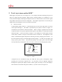
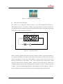
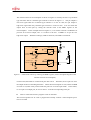
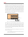
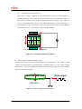
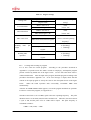
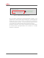
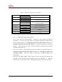
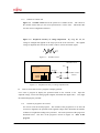
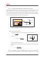
- When the read value is '0,' the switch can be determined to be in the on state.
- When the read value is '1,' the switch can be determined to be in the off state.
3.2
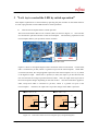
How to create and execute a program to control LEDs by switch operation
This section explains how to create a program to detect the switch operation state.
The
program also controls LED operation to enable you to visually know that the switch operation
state is detected.
The program applies the method of turning on the LED described in the
previous chapter.
3.2.1
Outline of program to be created
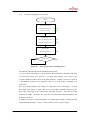
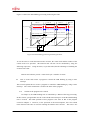
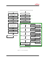
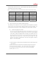
The operation of the program to be created is as described below.
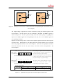
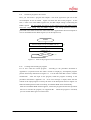
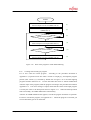
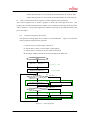
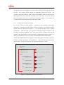
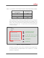
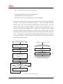
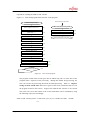
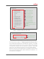
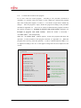
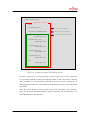
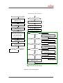
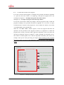
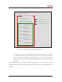
Figure 3.4 is the flow
of the program that performs the operation.
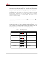
(1) When SW1 is pressed, LED1 is turned on.
(2) While SW1 is in the on state, LED1 is kept lighting.
(3) When SW1 is released (set to off), LED1 is turned off.
(4) Similarly, LED2 is turned on and off according to the SW2 state.
START
Set output pins for LED1 and LED2
(PDR1.bit0=1, PDR1.bit1=1)
-------------
Set input pins for SW1 and SW2
(DDR2.bit5=0, DDR2.bit7=0)
(1)
------------- (2)
(3)
SW1 input state?
PDR2.bit5 = 1
PDR2.bit5 = 0
(4)
Set LED1 to off (PDR1.bit0 = 1)
Set LED1 to on (PDR1.bit0 = 0)
(6)
SW2 input state?
(5)
PDR2.bit7 = 1
PDR2.bit7 = 0
(7)
Set LED2 to on (PDR1.bit1 = 0)
Figure 3.4
© Fujitsu
(8)
Set LED2 to off (PDR1.bit1 = 1)
Flow of program
-51-