1
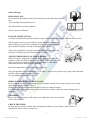
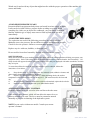
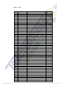
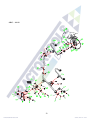
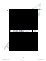
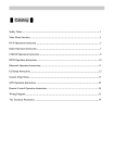
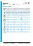
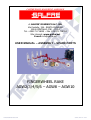
COSTRUZIONI MACCHINE AGRICOLE
di GALFRE’ DOMENICO & C. SRL
Via Centallo, 136 - ROATA CHIUSANI
12044 CENTALLO (CN) – ITALY
Tel. +390171.718005 – Fax +390171.718004
Sito internet: www.galfre.net
E-mail: [email protected]
USER MANUAL – ASSEMBLY – SPARE PARTS
FINGERWHEEL RAKE
AGW2/3/4/5/6 – AGW8 – AGW10
D
DE
EC
CL
LA
AR
RA
AT
TIIO
ON
NO
OF
FC
CO
ON
NF
FO
OR
RM
MIIT
TY
Y
The manufacturer
Galfrè Domenico & C. SRL
Via Centallo, 136 - ROATA CHIUSANI – 12044 CENTALLO (CN) Italy
Tel 0171.718005
Fax 0171.718004
declares under it responsibility that the machine:
FINGERWHEEL RAKE
Model ……………
Serial number n. ……………
Year .……………
fully complies with Essential Requisites for Safety
and for Safeguarding health set out in:
2006/42/CE
(Repealing Directives 98/37/Ce e 89/392/CEE)
With the aim of verify the conformity towards those directives,
we consult the harmonized standard:
EN 1553
UNI 10759
and technique specific:
ISO 11684
Centallo (CN), ___________________
The legal administrator
_____________________
1
AGW – MOUNTED HAY RAKE
2/3/4/5/6 wheel hay rake is easily adaptable to each type of tractor by its 3 point linkage. It is a machine
that saves a lot of time and work. Our machine can be used on each kind of field and it help farmers to
make work easier than previous. It is used for the seperating the green herb over the field to ventilate
them to dry in a short time. It can be used to collect the cutted plant stalks (barley, wheat stalks...)
together to put this in a standart row and bt this way the plant stalks return to the economy and obins
extra gain.
MODEL
LENGHT
AGW - 04
425 cm
WORKING
WIDTH
250 – 300 cm
TRANSPORT
WIDTH
140 cm
WEIGHT
WHEEL #
175 kg
4
AGW – 08 CARTED HAY RAKE
8 wheel hay rake is easily adaptable to each type of tractor by its 3 point linkage. By means of
high work capacity that saves a lot of time and work. Our machine can be used on each kind of field and
it help farmers to make work easier than previous. It is used for the seperating the green herb over the
field to ventilate them to dry in a short time. It can be used to collect the cutted plant stalks (barley,
wheat stalks...) together to put this in a standart row and bt this way the plant stalks return to the
economy and obtains extra gain.
MODEL
LENGHT
AGW - 08
670 cm
WORKING
WIDTH
520 – 610 cm
TRANSPORT
WIDTH
300 cm
WEIGHT
WHEEL #
485 kg
8
AGW – 10 CARTED HAY RAKE
10 wheel hay rake is easily adaptable to each type of tractor by its 3 point linkage .At pleasure GVR-10
can be turn into 8 wheel hay rake with one pin. By means of high work capasity that saves a lot of time
and work. Our machine can be used on each kind of field and it help professional farmers to make work
easier than previous .It is used for the seperatingthe green herb over the field to ventilate them to dry in a
short time. It can be used to collect the cutted plant stalks (barley , wheat stalks...) together to put this in
a standart row and by this way the plant stalks return to the economy and obtains extra gain.
MODEL
LENGHT
AGW - 10
760 cm
WORKING
WIDTH
520 – 700 cm
TRANSPORT
WIDTH
410 cm
2
WEIGHT
WHEEL #
580 kg
10
Safety Messages
READ MANUALS
Do not operate the machine unless the instructions in the following manuals
have
been carefully read and understood:
This Wheel Rake Operator’s Manual
Tractor Operator’s Manual
FOLLOW INSTRUCTIONS
Carefully read and understand all safety messages in this manual and on your machine safety decals.
Safety decals located on your machine contain important information
that will help you operate your equipment safely. Keep safety decals in
good condition. Replace missing or damaged safety decals.
Allow only responsible, properly instructed individuals to operate the
machine. Carefully supervise inexperienced operators.
TOWING IMPLEMENTS ON PUBLIC ROADS
Before towing the implement, attach the safety chain to the drawbar
support or other specified anchor location. Safety chains will reduce the
risk of injury due to collision or loss of vehicle control if the drawn
implement becomes unhitched from drawbar.
Provide enough slack in the chains to permit turning.
Obey all applicable laws regarding the use of lights, a slow moving vehicle sign, safety chain and other
possible requirements concerning road use.
Use good judgment and drive carefully.
REDUCE SPEED WHEN TOWING LOADS
Be sure that the tractor is large enough to have adequate braking and steering control when towing
implements that do not have brakes.
Reduce speed if towed load without breaks weighs more than the tractor.
Use additional caution when towing loads under adverse surface conditions, when turning, and on
inclines.
NO RIDERS
Be sure the tractor operator is the only person riding the tractor. Do not allow
riders on the machine.
CHECK THE FIELD
Be alert and use extreme caution when operating on hillsides or near ditches, gullies, holes, or
obstructions where rollover could occur.
3
Watch out for and avoid any object that might interfere with the proper operation of the machine (i.e.
stones and limbs).
AVOID HIGH PRESSURE LEAKS
Pressurized fluid can penetrate body tissue and result in serious injury or death.
Leaks can be invisible. Relieve pressure before working on system. When
searching for a leak, use an object like cardboard - not your hand. A surgeon
familiar with this type of injury must remove fluid injected under the skin
immediately.
AVOID TIRE EXPLOSION
Tire explosion can result if the following procedures are not to followed:
Maintain correct tire pressure. Do not inflate tire above recommended pressure.
Check for low tire pressure. Inflate to recommended pressure.
Replace any tire with cuts, bubbles, or damaged rims.
Do not weld or heat wheel assembly. Heating will increase tire pressure.
SAFETY DECALS
Safety decals located on your machine contain important and useful information that will help you operate your
equipment safely. Each of the safety decals is shown below and in the parts book under “decal assembly”. All
safety decals also appear elsewhere in the parts manual where they are displayed with other assemblies of which
they are a part.
To assure that all decals remain in place and remain in good condition, follow-theinstuctions. Given below:
1.
Keep decals clean. Use soap and water -Not mineral spirits, adhesive cleaners and
other similar cleaners that will damage the decal.
2.
Replace any damaged or missing decals. When attaching decals, the surface
temperature of the metal must be at least 40 degree F. The metal must also be clean and
dry,
3.
When replacing a machine component with a decal attached, replace the decal also.
4.
Purchase replacement decals from your Wheel Rakes dealer.
AUXILIARY HYDRAULIC CONTROL
Hydraulic control lever (B) is used to raise and lower the rake arms.
Some tractors have detents, which will not allow the tractor lever to
return to neutral on its own. The lever must be returned to neutral
manually to prevent overheating of the hydraulic system.
NOTE:Layout varies with tractor model. Consult your tractor
operator’s manual.
4
ASSEMBLY INSTRUCTIONS (AWG-10 02)
a)
Position the parking stand (1) 1 in its housing and lock it with the pin (2) Next, lay the
primary structure supplied assembled on the ground with the swinging pipe (20) upwards
picture 1.
18
17
6
20
21
1
Pict.1
b)
Slide the main pipe (26) into the swinging pipe (20) and retain with the supplied lever (22)
and pin (23) so that it is on axis with the three-point hitch (pict. 2).
26
26
5
Pict.2
c)
At AWG04 hay rake; attach the axles (27) to the main pipe (26) by the hel of flanges, side
lock lamas (22) and pin (25), as you see picture 3.
At AWG04 hay rake; attach the axle (27) from external to the inside as axle (27) and single axle (44),
44
27
27
27
27
Pict.3
d)
Attach the wheel assembly (43) to the hub (28) with bolt (23) and nut (42) according to for every
axle (27) 2 units, for single axle (44) 1 unit. For AWG-04 4 units
23 40
35
41
37
42
Pict.4
6
e)
Lift the wheels (x from the ground until they are in the working position.Above are the
instructions for the R.H. rake assembly. Please refer to the above instructions also for the L.H. rake
assembly. Most parts are interchangeable for both rakes only the specific parts are marked RIGHT or
LEFT.
f)
Unlock the primary structure with the supplied lever (22) and pin (25), turn it by 90 degrees and
lock it again with the same pin. Now the rake is properly positioned on the ground and you only have to
attach the remaining wheels as explained above.
The rake is now fully assembled and ready to be mounted to the tractor .
7
ASSEMBLING (AWG-10 01)
a)
Attch the drawbar (52) to the back frame (31) by bolt (27) and plate of frame (41). Attach the
jack (5) and wheel (36). Fig 29.
b)
Attach the lift arm RH and LH (33-22) to the back frame (31) with pin (28)
c)
Attach the lift (25) and hose 3.00m-3.25m (13-14) as it shown at the motaging AWG-10
d)
Attach the under of front arrangement RH-LH (34-35) to the lift arm RH-LH (33-22) by bolt (2)
and plate of arrangement (32)
8
e)
Attention that the lift hoses (13-14) mustn’t be free and must be attached to the drawbar with
hose collar (15)
f)
After you attach the pintle (1) with bolt-nut-washer (2-3-4).
g)
After you fnish the part montage of AWG-02 MONTAGE it the under front arrangement (34-35)
which is attached to the lift arm and start to use.
9
100 x 50mm tube
280m
260mm
155 x180mm
180m
HYD.CYL
70 x 330mm
485mm collapsed
ASSEMBLING
a)
Attach the frame RH (3) and frame LH (4) to each other by bolt (5) and nut, washer (12-13) as
you see at frame assembling. Look at the assembling AWG-10 02
b) Attach the connection lamas, as the shape of connection lama 1 (10) will be at the back and
connection lama 2 (11) in the front, to the frame 2 units from each as right and left, by the help of bolt
(9), nut (12) and washer (13). Picture .
10
Pict.7
c)
After than attach the frame to the tractor by the help of somebody or by crane with in (6)and
linch pin (7).pict.8
Pict.8
When the rake is ready to be mounted to the tractor ( pict. 6) attach the lifting arms to the pins on both
sides of the primary structure (1). Next, attach the three-point arm to the cap (15) of the primary
structure with the pin. Now lift the rake to its highest setting and for transport lock with the pin (19) for
no rake floating (pict. 7). Retain the part (14) to the crossbar (1) with the pin (9) into hole 1 (pict. 15) of
the above said crossbar. Now turn the main pipe (24) and bring the rake to the vertical position for
transport (pict. 10)
Never operate the rake with the pin (19) in the locked position. The locked position is for transport only
11
14
16
15
18
19
transporting locked-working unlocked
1
Pict.9
Pict.10
AWG-08 and AWG-10 V-rakes are made as follows:
1 main frame (1) complete of hitches (4-12)
1 R.H. RP- 4 or RP- 5 rake. Duly assembled as above.
1 L.H. RP- 4 or RP- 5 rake, duly assembled as above.
On the R.H. and L.H. GR-04 and GR-05 rakes only the wheel arms and the wheels are specific, all other
parts are interchangeable for both rakes. The specific parts are marked RIGHT (for the RH. rake and
LEFT for the L.H. rake).
12
OPERATING INSTRUCTIONS
The rake is suitable for:
1)
RAKING (pict. 16) Turn the
main pipe (26) with the bend to the
left. Turn the wheel arms (27) (on RP5 rake turn the wheel arm 55 as well)
with the bend to the left.
2)
SPREADING (pict. 17) Turn
the main pipe (3) with the bend to the
left Turn the wheel arms (27)
3)
TURNING (pict. 15) Turn the main pipe (3d) with the bend to the right. Turn the wheel arms
(27) (on GR-5 rake turn the wheel arm 55 as well) with the bend to the left.
Above we have described
how to set a R.H. rake for the
different operations. If you need
to set a L.H. rake for the above
operations, please refer to
pictures 16-17 and 18 of V-rakes.
Insert the hitches (1-15) of front arrangement to the bolted lamas (10-11) on frame and lock it with
pin (8) and linch pin (7)
13
For the V-rakes transport please refer to the AWG-04 rake transport.
Pictures 13 and 14 below show the transport position of AWG-08 and AWG-10 V - rakes
Before operating the rake and after you have reached the field, unlock pin (21) (pict. 7 and
re1evant notes). This will enable the rake to float independent of the Mainframe.
Next, adjust the rake angle by positioning the pin (11) into the holes 2 to 7 (pict. 15). Hole is for
transport only.
14
AWG-8 and AWG-10 rakes are properly designed for windrowing, as ideal implement to
complement
the big halers. Slide the AWG-4 rakes on the frame (1) to get different working widths.
Below (pict. 19-20) is the ideal positioning of the rake for a swath suitable for a 5 pick-up baler.
15
PROBLEM
1) Wheel does not unload hay
2)
Tine failure
3)
The rake does not
collect the hay
CAUSES
1) New tine, too much
paint on it.
2) Mud on tine point due
to moist soil.
1)
Going backwards with
wheels not lifted,
REMEDIES
Have the wheels be turning on
gravelly soil until the tine is
clean again.
2)
The wheels are too
close to the
ground
1)
Lift the wheels before
going backwards
2)
Too much pressure on
the wheels.
2)
Lightly lift the rake.
3)
3)
Protect it by oiling.
Tine rusted.
1) The wheel is too much
vertical inclined angle to the
ground
1)
By setting the 3rd point
arm, bring the wheel vertical to
the ground.
2)
Replace it. We recommend replacing all tines worn
to a uniform height.
2) Tine worn out.
4)
Too much floating 1) Wheels too far from ground.
of wheels.
1)
5)
1
Going backwards with
the wheels not lifted,
1)
Lift the wheels when
going backwards
2)
Too much speed on
rough soil.
Reduce speed.
Bent tine
Slightly lower the rake.
Going across deep and narrow Reduce your speed
ditches
Too much weight on the wheels. 4)
Lightly lift the rake.
16
SAFETY PRECAUTIONS
Picture Parts
No:
code
--
Parts Name
Using Aim
Chain
To hinder being
damaged the rake’s arm
or attachment
components because of
much loading during the
transporting.
To prevent damaging
the front arrangement
and its components
because of rocking its
self during the
transporting.
01 – 50
01 – 51
Under Lock
Lama
--
AWG10
03 –
01
02 – 16
02 – 17
Side Lock
Lama
Cultıvator
Linch
--
AWG
04
02 – 13
Wire Stand
Plate
02 – 35
Problem
Any of
components could
be broken or
damaged because
of rocking during
the transporting.
The front
arrangement could
cause damaging to
its self and
components
because of rocking
its self during the
transporting.
To hinder being
The attachment of
damaged of the
main pipe and
attachment of main pipe front arrangement
and front arrangment to to each other could
each other because of
be damaged
being shaked during the because of being
operating in the field.
shaked during the
operating in the
field.
Especially to reduce the The back pipe of
effect of being damaged front arrangement
bacause of being shaked could damage the
during the operating and system with hard
prevent the machine
and sudden strokes
being damaged for this
because of effects
reason.
of shaking.
To increase the life of
The grass
montage and to prevent collection wire
the getting out of gragg could get out of its
collection wire its
housing and / or
housing because of
the bolts and nuts
making pressure on the could be out of use
tines which are on the
because of being
rake part.
deformed.
17
Precautions
Project chain
between two
arm.
Project under
locl lama.
Project the side
lock lama
Assemb the
cultivator linch.
Project the wire
stand plate.
AWG – 04
42
18
24
19
17
16
14
8
14
13 20
15
7
12
23
13
6
9
10
11
12
25
22
21
25
12
42
18
NO
1
2
3
4
5
6
7
8
9
10
11
12
13
14
15
16
17
18
19
20
21
22
23
24
25
26
27
28
29
30
31
32
33
34
35
36
37
PART #
AWG-04 01
AWG-04 02
AWG-04 03
AWG-04 04
AWG-04 05
AWG-04 06
AWG-04 07
AWG-04 08
AWG-04 09
AWG-04 10
AWG-04 11
AWG-04 12
AWG-04 13
AWG-04 14
AWG-04 15
AWG-04 16
AWG-04 17
AWG-04 18
AWG-04 19
AWG-04 20
AWG-04 21
AWG-04 22
AWG-04 23
AWG-04 24
AWG-04 25
AWG-04 26
AWG-04 27
AWG-04 28
AWG-04 29
AWG-04 30
AWG -04 31
AWG -04 32
AWG -04 33
AWG -04 34
AWG -04 35
AWG -04 36
AWG -04 37
38
39
40
41
42
43
AWG -04 38
AWG -04 39
AWG -04 40
AWG -04 41
AWG -04 42
AWG -04 43
DESCRIPTION
Support
R Lock Pin M7
Under of front arrangement
Bolt M12*90
Nut M12
Front arrangement
Castle nut 7/8
Cottor Pin 5/5
Pin M24
AWGease nipple M8
Pin M16
R Lock Pin M4
Bolt M12*120
Nut M12
İntermediate tube
Upper spring retainig plate
Middle link coupling
Suspension spring M10*50
Lower spring retainig plate
Connection bar
Lower lock lama
Side lock lama
Bolt M12*40
Barbed spangle M12
Pin M12
Main pipe
Axis
Completed hub
Gaiters circle
Bearing 6205
Hub
Bearing 4204
Hub cover
Piston ring
Nut ¾
Circle
Grass concentration wire
¢6,5mm
Pan -head bolt 3/8*25
NC Nut 3/8
Wire stand plate
Rim sheet metal
Fiber bolt M12
Collected wire circle
19
PIECE
1
1
1
1
1
1
1
1
1
5
1
5
2
2
1
1
1
2
1
1
1
3
10
2
4
1
2
4
4
4
4
4
4
4
4
4
160
80
80
40
4
9
4
AWG – 04
AWG – 10 01
51
22
50
35
2
25
20
19
17
46
47 48
51
49
16
28
27
15
36
45 44
43
42
41
29
31
40
39
38
30
14
37
6
18
3 7
26
4
34
52
3
12
10
11
8
1
4
2
13
18 19 20
21
23
7
9
32
24
2
6
5
20
33
AWG – 10 01
NO
1
2
3
4
5
6
7
8
9
10
11
12
13
14
15
16
17
18
19
20
21
22
23
24
25
26
27
28
29
30
31
32
33
34
35
36
37
38
39
40
41
42
43
44
45
46
47
48
49
50
51
52
PART #
AWG-01 01
AWG-01 02
AWG-01 03
AWG-01 04
AWG-01 05
AWG-01 06
AWG-01 07
AWG-01 08
AWG-01 09
AWG-01 10
AWG-01 11
AWG-01 12
AWG-01 13
AWG-01 14
AWG-01 15
AWG-01 16
AWG-01 17
AWG-01 18
AWG-01 19
AWG-01 20
AWG-01 21
AWG-01 22
AWG-01 23
AWG-01 24
AWG-01 25
AWG-01 26
AWG-01 27
AWG-01 28
AWG-01 29
AWG-01 30
AWG-01 31
AWG-01 32
AWG-01 33
AWG-01 34
AWG-01 35
AWG-01 36
AWG-01 37
AWG-01 38
AWG-01 39
AWG-01 40
AWG-01 41
AWG-01 42
AWG-01 43
AWG-01 44
AWG-01 45
AWG-01 46
AWG-01 47
AWG-01 48
AWG-01 49
AWG-01 50
AWG-01 51
AWG-01 52
DESCRIPTION
Pıntle
Bolt
Fibre nut M16
Washer M16
Jack
Pin M14
Cottor pin
Bolt
Bolt
Mace
Washer
Nut
Hose 3.00m
Hose 3.25m
Hose collar
UNF T ¾
R2 90° corner hose 3/8*33cm
R2 90° corner hose 3/8*40cm
UNF Nipple ¾
Washer ¾
UNF T ¾
Lift arm RH
Circlip
Pin of lift
Lift
Headgear
Bolt M16*150
Pin
Bolt
Nut
Back frame
Plate of front arrangement
Lift arm LH
Under of front arrangement LH
Under of front arrangement RH
Wheel
Bolt
Nut
Ring
Hub assembly
Plate of frame
Oil seal
Bearing
Pin
Hub
Grease nipple
Cap of hub
Nut
Bearing
Chain
Safety pin
Drawbar 21
PIECE
1
10
10
10
1
3
3
1
1
1
1
1
1
1
2
1
1
2
4
4
1
1
2
2
2
2
4
2
2
2
1
2
1
1
1
2
2
2
2
2
1
2
2
10
2
2
2
2
2
1
2
1
AWG – 10 02
22b
22a
21
18
17
20
22
19
7
02
NO
1
2
3
4
5
6
7
8
9
10
11
12
13
14
15
16
17
18
19
20
21
22a
22b
23
24
25
26
27
28
29
30
31
32
33
34
35
36
37
38
PART #
AWG-02 01
AWG-02 02
AWG-02 03
AWG-02 04
AWG-02 05
AWG-02 06
AWG-02 07
AWG-02 08
AWG-02 09
AWG-02 10
AWG-02 11
AWG-02 12
AWG-02 13
AWG-02 14
AWG-02 15
AWG-02 16
AWG-02 17
AWG-02 18
AWG-02 19
AWG-02 20
AWG-02 21
AWG-02 22
AWG-02 23
AWG-02 24
AWG-02 25
AWG-02 26
AWG-02 27
AWG-02 28
AWG-02 29
AWG-02 30
AWG-02 31
AWG-02 32
AWG-02 33
AWG-02 34
AWG-02 35
AWG-02 36
AWG-02 37
AWG-02 38
AWG-02 39
DESCRIPTION
Front arrangement
Castle nut 7/8
Cotter pin 5/5
Pin M24
Grease nipple
Pin M16
Cottor pin M4
Bolt M12*120
Nut M12
Intermediate tube
Upper spring retaing plate
Washer M12
Suspension spring 10*50
Lower spring retaing plate
Connection bar
Lower lock lama
Side lock lama
Bolt M12*40
Pin M12
Nut M12
Hub assemply
Single axis
Axis
Main pipe
Gaiters circle
Bearing 6205
Hub
Bearing 4204
Hub cover
circlip
Nut ASA-B-18-2-2
circle
Grass concentrtion wire
Pan head bolt 6/8
NC nut 3/8
Wire standplate
Rim sheet metal
Wheel assemply LH
Wheel assemply RH
23
PIECE
2
2
2
2
12
2
12
4
5
2
2
4
4
2
2
2
8
11
5
10
10
2
4
2
10
10
10
10
10
10
10
10
400
200
200
100
10
5
5
AWG – 10
NOTE :
………………………………………………………………………………………………………
………………………………………………………………………………………………………………
………………………………………………………………………………………………………………
………………………………………………………………………………………………………………
………………………………………………………………………………………………………………
………………………………………………………………………………………………………………
………………………………………………………………………………………………………………
………………………………………………………………………………………………………………
………………………………………………………………………………………………………………
………………………………………………………………………………………………………………
………………………………………………………………………………………………………………
………………………………………………………………………………………………………………
………………………………………………………………………………………………………………
………………………………………………………………………………………………………………
………………………………………………………………………………………………………………
………………………………………………………………………………………………………………
………………………………………………………………………………………………………………
………………………………………………………………………………………………………………
………………………………………………………………………………………………………………
………………………………………………………………………………………………………………
………………………………………………………………………………………………………………
………………………………………………………………………………………………………………
………………………………………………………………………………………………………………
………………………………………………………………………………………………………………
………………………………………………………………………………………………………………
………………………………………………………………………………………………………………
………………………………………………………………………………………………………………
………………………………………………………………………………………………………………
………………………………………………………………………………………………………………
………………………………………………………………………………………………………………
………………………………………………………………………………………………………………
………………………………………………………………………………………………………………
………………………………………………………………………………………………………………
………………………………………………………………………………………………………………
………………………………………………………………………………………………………………
………………………………………………………………………………………………………………
………………………………………………………………………………………………………………
………………………………………………………………………………………………………………
………………………………………………………………………………………………………………
………………………………………………………………………………………………………………
………………………………………………………………………………………………………………
………………………………………………………………………………………………………………
………………………………………………………………………………………………………………
………………………………………………………………………………………………………………
………………………………………………………………………………………………………………
24
………………………………………………………………………………………………………………
………………………………………………………………………………………………………………
………………………………………………………………………………………………………………
………………………………………………………………………………………………………………
………………………………………………………………………………………………………………
………………………………………………………………………………………………………………
………………………………………………………………………………………………………………
………………………………………………………………………………………………………………
NOT : ………………………………………………………………………………………………………
………………………………………………………………………………………………………………
………………………………………………………………………………………………………………
………………………………………………………………………………………………………………
………………………………………………………………………………………………………………
………………………………………………………………………………………………………………
………………………………………………………………………………………………………………
………………………………………………………………………………………………………………
………………………………………………………………………………………………………………
………………………………………………………………………………………………………………
………………………………………………………………………………………………………………
………………………………………………………………………………………………………………
………………………………………………………………………………………………………………
………………………………………………………………………………………………………………
………………………………………………………………………………………………………………
………………………………………………………………………………………………………………
………………………………………………………………………………………………………………
………………………………………………………………………………………………………………
………………………………………………………………………………………………………………
………………………………………………………………………………………………………………
………………………………………………………………………………………………………………
………………………………………………………………………………………………………………
………………………………………………………………………………………………………………
………………………………………………………………………………………………………………
………………………………………………………………………………………………………………
………………………………………………………………………………………………………………
………………………………………………………………………………………………………………
………………………………………………………………………………………………………………
………………………………………………………………………………………………………………
………………………………………………………………………………………………………………
………………………………………………………………………………………………………………
………………………………………………………………………………………………………………
………………………………………………………………………………………………………………
………………………………………………………………………………………………………………
………………………………………………………………………………………………………………
………………………………………………………………………………………………………………
………………………………………………………………………………………………………………
………………………………………………………………………………………………………………
………………………………………………………………………………………………………………
………………………………………………………………………………………………………………
………………………………………………………………………………………………………………
………………………………………………………………………………………………………………
………………………………………………………………………………………………………………
………………………………………………………………………………………………………………
25
………………………………………………………………………………………………………………
………………………………………………………………………………………………………………
………………………………………………………………………………………………………………
………………………………………………………………………………………………………………
………………………………………………………………………………………………………………
………………………………………………………………………………………………………………
………………………………………………………………………………………………………………
………………………………………………………………………………………………………………
………………………………………………………………………………………………………………
………………………………………………………………………………………………………………
26