1
CalTool™ for molbloc™
A PC Based Calibration Utility
For molbloc Flow Elements
User’s Manual
©1999 DH Instruments, Inc.
CalTool™ for molbloc™ User’s Manual
2SQRZ\O]]_\OVS[_SN]KXNQK]O]K\OZY^OX^SKVVcRKdK\NY_]/XO\Qc]^Y\ONSX^RO]OVS[_SN]KXNQK]O]MKX
LO \OVOK]ON _XObZOM^ONVc KXN aS^R Ob^\OWO PY\MO 2SQR Z\O]]_\O ]c]^OW] ]RY_VN LO K]]OWLVON KXN
YZO\K^ONYXVcLcZO\]YXXOVaRYRK`OLOOXSX]^\_M^ONSXZ\YZO\]KPO^cZ\KM^SMO]
© 1999 DH Instruments, Inc. All rights reserved.
Information in this document is subject to change without notice. No part of this document may be reproduced or
transmitted in any form or by any means, electronic or mechanical, for any purpose, without the express written
permission of DH Instruments, Inc. 4765 East Beautiful Lane Phoenix AZ 85044-5318 USA.
DH Instruments makes sincere efforts to ensure accuracy and quality of its’ published materials; however, no
warranty, expressed or implied, is provided. DH Instruments disclaims any responsibility or liability for any direct or
indirect damages resulting from the use of the information in this manual or products described in it. Mention of any
product does not constitute an endorsement by DH Instruments of that product. This manual was originally
composed in English and was subsequently translated into other languages. The fidelity of the translation cannot
be guaranteed. In case of conflict between the English version and other language versions, the English
version predominates.
DH Instruments, DH, DHI, molbloc, molbox, molbox1 and CalTool, are trademarks, registered and otherwise of
DH Instruments, Inc.
Document No. 550117
991210
Printed in the USA
©1999 DH Instruments, Inc.
CalTool™ for molbloc™ User’s Manual
>+,6/90-98>/8>=
TABLE OF CONTENTS ................................................................................ i
FIGURES ................................................................................................. iii
TABLES ................................................................................................... iii
ABOUT THIS MANUAL .............................................................................. iv
1. INTRODUCTION .................................................................................... 1
1.1
PRINCIPLES ............................................................................................................................................. 1
1.1.1
1.1.2
1.1.3
HOW molbloc/molbox DETERMINES MASS FLOW.................................................................................... 1
RECALIBRATION OF molbloc/molbox........................................................................................................ 3
HOW CALTOOL FOR molbloc WORKS ....................................................................................................... 3
2. GETTING STARTED ............................................................................... 5
2.1
2.2
SYSTEM REQUIREMENTS ...................................................................................................................... 5
INSTALLING CALTOOL FOR molbloc.................................................................................................... 5
2.2.1
2.2.2
WINDOWS 95, 98, NT.................................................................................................................................... 5
RUNNING THE PROGRAM ........................................................................................................................... 6
3. NORMAL OPERATING PROCEDURES ..................................................... 7
3.1
TYPICAL START TO FINISH CALIBRATION PROCEDURE .................................................................. 7
3.1.1
3.1.2
3.1.3
3.1.4
3.2
3.3
SETTING UP TO RUN A CALIBRATION....................................................................................................... 8
RUNNING A CALIBRATION.......................................................................................................................... 8
USING A molbloc/molbox AS THE REFERENCE MASS FLOW STANDARD .......................................... 11
PRECAUTIONS TO ASSURE GOOD MEASUREMENTS ........................................................................... 11
MANUAL CREATION OF A CALIBRATION DATA FILE....................................................................... 12
CREATING AND USING molbloc RESTORE FILES............................................................................. 13
4. MAIN MENU OPTIONS ......................................................................... 15
4.1
[CALIBRATION] MENU .......................................................................................................................... 15
4.1.1
4.1.2
4.1.3
4.1.4
4.2
[SETUP] MENU....................................................................................................................................... 21
4.2.1
4.2.2
4.3
[INTERFACE]............................................................................................................................................... 21
[TEST GAS] ................................................................................................................................................. 23
[DATA] MENU......................................................................................................................................... 23
4.3.1
4.3.2
4.3.3
4.3.4
4.3.5
4.4
[CALIBRATION TEST] ................................................................................................................................ 15
4.1.1.1 CALIBRATION TEST/VERIFICATION TEST RUN SCREEN ....................................................... 17
4.1.1.2 RUN TEST TOOLBAR ................................................................................................................. 18
[VERIFICATION TEST]................................................................................................................................ 19
[CALCULATION] ......................................................................................................................................... 19
[EXIT]........................................................................................................................................................... 20
[CREATE] .................................................................................................................................................... 23
[EDIT]........................................................................................................................................................... 24
[PLOT] ......................................................................................................................................................... 25
[PRINT] ........................................................................................................................................................ 25
[VIEW].......................................................................................................................................................... 25
[TOOLS] MENU ...................................................................................................................................... 26
4.4.1
4.4.2
4.4.3
4.4.4
[REMOVE GAS CALIBRATION].................................................................................................................. 26
[RESTORE molbloc] ................................................................................................................................... 27
[CREATE RESTORE FILE] ......................................................................................................................... 27
[VIEW molbloc CALIBRATION].................................................................................................................. 28
Page i
©1999 DH Instruments, Inc.
CalTool™ for molbloc™ User’s Manual
4.4.5
4.5
[CHANGE molbloc CALIBRATION DATE] ................................................................................................. 28
[WINDOW] MENU ................................................................................................................................... 28
5. CALTOOL FILE TYPES AND CHARACTERISTICS .................................. 29
5.1
5.2
5.3
5.4
INTRODUCTION ..................................................................................................................................... 29
DATA FILE .............................................................................................................................................. 29
RESULT FILE.......................................................................................................................................... 30
molbloc RESTORE FILE........................................................................................................................ 31
6. molbloc NOMINAL FLOW RANGE/SIZE DESIGNATIONS AND ACTUAL PRESSURE
RANGES WITH VARIOUS GASES ............................................................... 33
6.1
6.2
molbloc SIZE AND RANGE DESIGNATIONS ....................................................................................... 33
molbloc PRESSURE DEPENDENT CALIBRATION TYPES ................................................................. 34
7. GLOSSARY ......................................................................................... 37
©1999 DH Instruments, Inc.
Page ii
CalTool™ for molbloc™ User’s Manual
031?</=
Figure 1.
Figure 2.
Figure 3.
Figure 4.
Figure 5.
Figure 6.
Figure 7.
molbloc/molbox Mass Flow (qm) Determination ........................................................................2
Calibration Test/Verification Test Run Screen .........................................................................17
Calculation/Activation Screen...................................................................................................20
Interface Setup Window ...........................................................................................................22
Interface Setup Window, RS232 Settings ................................................................................22
Test Data Entry Form...............................................................................................................24
Remove Gas Window ..............................................................................................................26
>+,6/=
Table 1.
Table 2.
Table 3.
Table 4.
Tools Available on the Run Test Toolbar .................................................................................18
molbloc Size and Nominal Range Designations ......................................................................34
molbloc Ranges with Low Pressure Calibrations .....................................................................35
molbloc Ranges with High Pressure Calibrations ....................................................................36
Page iii
©1999 DH Instruments, Inc.
CalTool™ for molbloc™ User’s Manual
+,9?>>23=7+8?+6
Manual Conventions
This manual is intended to provide the user with the information necessary to use CalTool for
molbloc software to adjust molbloc mass flow elements.
Before using the manual, take a moment to familiarize yourself with the table of contents structure.
Do not attempt to use CalTool for molbloc for molbloc without using this manual to understand its
principles and operation. Invalid molbloc calibrations can result from incorrect use of CalTool.
Certain words and expressions have specific meaning as they pertain to CalTool, molbloc
and molbox. The Glossary Section (Section 7) is useful as a quick reference for definitions of specific
words and expressions as they are used in the manual.
[ ] indicates CalTool menu, tab selections or icons (for example [Data]). Menu or tab selection paths
are always described hierarchically from highest to lowest level. For example: [Tools], [Options].
< > indicates COMPASS text displays such as screen names, field names, prompts, warnings
and instructions. For example: <Enter user ID>.
-+?>398S]_]ONSX^ROWKX_KV^YSNOX^SPc_]O\aK\XSXQ]KXNMK_^SYX]
89>/S]_]ONSX^ROWKX_KV^YSNOX^SPcYZO\K^SXQKXNKZZVSMK^SYX]KN`SMOKXNKNNS^SYXKVObZVKXK^SYX]
©1999 DH Instruments, Inc.
Page iv
CalTool™ for molbloc™ User’s Manual
3 8><9.?->398 CalTool™ for molbloc™ is a PC based calibration utility intended to be used to adjust molbloc mass
flow elements to agree with a mass flow reference at a particular operating pressure.
CalTool is run on a PC that is interfaced with a molbox1 or molbox RFM mass flow terminal.
CalTool runs mass flow intercomparisons, collects intercomparison data, calculates new molbloc
calibration coefficients, predicts and displays test data with the new coefficients and writes new
calibration coefficients to the molbloc.
WYVLVYM]KXNWYVLYbK\OXY\WKVVcMKVSL\K^ONK]SXNOZOXNOX^OVOWOX^]>ROWYVLYbMKVSL\K^SYXMYX]S]^]
YP MKVSL\K^SXQ ^RO WYVLYb Z\O]]_\O^\KX]N_MO\]=OO^ROWYVLYb9ZO\K^SYXKXN7KSX^OXKXMO7KX_KV
PY\WYVLYbMKVSL\K^SYXSXPY\WK^SYX
35,1&,3/(6
+2:PROEORFPROER['(7(50,1(60$66)/2:
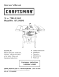
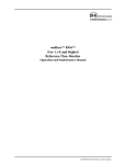
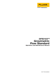
molbloc mass flow elements are laminar flow elements intended to be used with a molbox
(molbox1 or molbox RFM) mass flow terminal. The molbox measures the temperature of the
molbloc and the molbloc upstream and downstream pressures. Using the pressure and
temperature information and gas characteristics stored in molbox memory, molbox calculates
the density and viscosity of the flowing gas. From the density and viscosity of the flowing gas,
the differential pressure across the molbloc and molbloc specific calibration coefficients stored
on the molbloc EEPROM, molbox calculates the mass flow through the molbloc (see
Figure 1).
The model used by molbox to calculate molbloc flow is proprietary. molbloc specific
calibration coefficients are determined in the original factory calibration. Since the molbloc is a
static, stainless steel element, the molbloc calibration coefficients are stable over time.
Page 1
©1999 DH Instruments, Inc.
CalTool™ for molbloc™ User’s Manual
(P1 − P2 )ρ( P,T )
qm =
η( P ,T )
• CG (Re )
Where:
ρ ( P ,T ) =
P•M
Z ( P ,T ) • R • T
qm
π • η ( P ,T )
Re =
Determined by
Known from
Determined from
Measurement
Gas Properties
Gravimetric Calibration
P1
M
CG
P2
Z(P,T)
T
h(P,T)
And:
qm
=
mass flow
[kg/s]
P1
=
upstream absolute pressure
[Pa]
P2
=
downstream absolute pressure
[Pa]
P
=
P1 − P2
2
[Pa]
T
=
absolute temperature of gas
[k]
η(P,T)
=
dynamic gas viscosity under P,T conditions
[Pa•s]
CG
=
geometry of molbloc flow path and
Reynolds number dependence
[m ]
Re
=
Reynolds number
[-]
M
=
molecular weight of the gas
[g/mol]
Z(P,T)
=
compressibility factor of the gas under
P,T conditions
[-]
R
=
universal gas constant
J
kg • mol • k
r
=
radius of the piston
[m]
3
Figure 1. molbloc/molbox Mass Flow (qm) Determination
©1999 DH Instruments, Inc.
Page 2
CalTool for molbloc User’s Manual
5(&$/,%5$7,212)PROEORFPROER[
The molbox mass flow terminal and molbloc mass flow elements are calibrated separately.
Calibration of a molbox consists of calibrating the molbox pressure transducers and,
possibly, verifying its ohmic measurement system which reads the molbloc platinum
resistance thermometers. molbox calibration procedures are described in the molbox
Operation and Maintenance Manual.
Calibration of a molbloc consists of comparing the mass flow measured by the combination
of the molbloc and a calibrated molbox to a suitable mass flow standard flowing the gas for
which the calibration is being performed. Since the molbloc is a static, stainless steel element,
characterized by proprietary calibration coefficients determined in the original factory
calibration, an out of tolerance molbloc is usually considered to require repair. CalTool for
molbloc software is available for facilities requiring the capability to adjust molblocs to agree
with their mass flow standard.
+2:&$/722/)25PROEORF:25.6
CalTool for molbloc supports the adjustment of certain proprietary molbloc coefficients to fit
the molbloc mass flow measurements to a mass flow standard for a specific gas at a specific
molbloc operating pressure.
The proprietary molbloc calibration coefficients manipulated by CalTool for molbloc are
designated CG(Re=0) and β (beta). CG(Re=0) is the value of CG extrapolated to a Reynolds number
of zero (i.e., null flow) and β is the slope of the variation of CG with Reynolds number.
CalTool for molbloc does not adjust molbloc calibration coefficients relating to compensation
for changes in operating pressure. Therefore, adjustments made to a molbloc using CalTool
for molbloc must be made using data collected at a single, stable upstream or downstream
molbloc pressure and, following the calibration, the molbloc must always be used at the
upstream or downstream pressure at which it was calibrated. This is the equivalent of a
“single P calibration” (see molbox Operation and Maintenance Manual).
CalTool for molbloc makes separate gas specific adjustments for each gas that is flowed.
Therefore, individual calibrations and molbloc adjustments must be made for each
desired gas. CalTool for molbloc can be used to add gas calibrations for a molbloc.
Added gas calibrations, like all molbloc calibrations using CalTool for molbloc, are only valid
at the upstream or downstream pressure at which the molbloc is calibrated. This is the
equivalent of a “single P calibration” (see molbox Operation and Maintenance Manual).
CalTool for molbloc includes all the tools necessary to run comparisons between molblocs
and a mass flow standard, acquire data from the comparison, calculate new calibration
coefficients and write the coefficients to the molbloc. It also includes tools to enter test data
manually, edit test data, view calibration results, change the molbloc calibration date and
create and load molbloc restore files.
+]aS^RKXcMKVSL\K^SYX^RO\O]_V^]YPKWYVLVYMMKVSL\K^SYXK\OYXVcK]QYYNK]^ROWK]]PVYa
]^KXNK\N_]ONK]K\OPO\OXMOKXN^ROSX^OQ\S^cYP^ROMKVSL\K^SYXMYWZK\S]YXZ\YMO]]
Page 3
©1999 DH Instruments, Inc.
CalTool™ for molbloc™ User’s Manual
89>/=
©1999 DH Instruments, Inc.
Page 4
CalTool™ for molbloc™ User’s Manual
1 />>381 = >+<>/. This section explains how to install CalTool for molbloc on your computer and provides an overview
of the startup procedures.
6<67(05(48,5(0(176
CalTool for molbloc requires a minimum PC configuration and a molbox1 or molbox RFM for data
collection and communication with the molbloc.
If your PC does not meet these minimum requirements, the software will not run as designed.
•
Windows 95, 98 or NT
•
75 MHz Pentium
•
8 Mbytes of Ram
•
7 Mbytes of free hard disk space
•
At least one available RS232 port and/or National Instruments Corporation IEEE-488
interface card
,167$//,1*&$/722/)25PROEORF
:,1'2:617
å Start Windows operating system.
Insert the CalTool for molbloc CD into your CD drive.
ê The CalTool setup program will automatically run.
If it does not, press the Start button, then select Run. In the Run dialog box, type
D:\disk1\setup.exe, depending on label of the CD drive you placed the installation disk.
The setup program will step through the installation process prompting you for entry of the
necessary information.
ñ To run CalTool for molbloc press the Start Button, select Programs, then select CalTool
for molbloc and click on the CalTool icon.
Page 5
©1999 DH Instruments, Inc.
CalTool™ for molbloc™ User’s Manual
5811,1*7+(352*5$0
Before running CalTool, establish a remote connection between a molbox1 or molbox RFM
and the host PC. Do this by connecting your PC to the molbox using a standard RS232 cable
and connecting one of the PC’s communications ports to the molbox’s Com1 port.
National Instruments Corporation IEEE-488 cards are also supported by CalTool for remote
communication using the molbox’s IEEE-488 interface. IEEE-488 users should connect a
IEEE-488 cable to the IEEE-488 port on the molbox and to the desired IEEE-488 card in the
host PC.
See the molbox Operation and Maintenance Manual, Remote Section, for additional
information on molbox communication interfaces and settings.
Once you have set up the interface between the molbox and the PC, you are ready to
run CalTool. Click the CalTool Icon in the CalTool program group in the Start menu.
When CalTool for molbloc loads, it assumes the communication settings that were in use
when the program was last run. All program options that require a remote interface with a
molbox use these settings. See Section 4.2.1 to change CalTool interface setups.
©1999 DH Instruments, Inc.
Page 6
CalTool™ for molbloc™ User’s Manual
8 9<7+6 9 :/<+>381
: <9-/.?</= 7<3,&$/67$5772),1,6+&$/,%5$7,21352&('85(
The typical start to finish calibration procedure includes:
å Setting up to run the calibration (see Section 3.1.1).
Running the calibration (see Section 3.1.2).
ê Calculating and evaluating calibration results (see Section 3.1.2).
Writing new calibration coefficients to the molbloc see Section 3.1.2).
Verifying calibration results (if desired) (see Section 4.1.2).
ñ Creating the molbloc restore file (see Section 3.3).
+]OZK\K^OMKVSL\K^SYXS]\O[_S\ONPY\OKMRQK]aS^RaRSMR^ROWYVLVYMS]^YLO_]ON
Page 7
©1999 DH Instruments, Inc.
CalTool™ for molbloc™ User’s Manual
6(77,1*8372581$&$/,%5$7,21
:\SY\^YMKVSL\K^SXQKWYVLVYMPY\^ROPS\]^^SWOK\O]^Y\OPSVOYP^ROObS]^SXQWYVLVYM]RY_VNLO
M\OK^ONSPYXOS]XY^K`KSVKLVO>RO\O]^Y\OPSVOaSVVKVVYa^ROWYVLVYM^YLO\O]^Y\ON^YS^]K]
\OMOS`ON]^K^O]RY_VNcY_aS]R^Y\O`O\]O^ROMKVSL\K^SYXZ\YMO]]
To set up and prepare the molbloc for calibration:
å Connect the molbloc to a calibrated molbox following the instructions in the molbox
Operation and Maintenance Manual. The molbox must be properly calibrated for the
molbloc calibration to be valid.
Connect the molbloc to be calibrated in series with the mass flow standard that is serving
as the reference. The molbloc must be installed so that the upstream or downstream
pressure will be stable throughout the calibration. The fixed upstream or downstream
pressure must be the same pressure at which the molbloc will be used in
normal operation. If the molbloc is normally used in a molstic, calibrate the molbloc
mounted in the molstic with the molstic pressure regulator at its normal setting.
CalTool for molbloc adjustments are only valid for the operating pressure at which the
calibration comparison is performed.
ê Install a means to set a stable flow rate over the range of the molbloc. This could be a
manual needle valve, a mass flow controller or a component of the mass flow standard.
If the molbloc is normally used at an elevated static pressure with a constant upstream
pressure, the flow control element is usually placed downstream of the molbloc. If the
molbloc is used downstream with atmospheric or near atmospheric downstream pressure,
the flow control device is usually placed upstream of the molbloc.
Install a valve to shut-off the flow upstream of the molbloc and the reference mass
flow standard.
Connect a supply of the gas to be calibrated. Generally, gases with purity of 99.99 % or
better should be used to achieve normal molbloc specifications.
5811,1*$&$/,%5$7,21
Running the molbloc calibration consists of comparing the measurements of molbloc/molbox
and the mass flow standard used as a reference at various flows within the molbloc range and
logging data at each flow point. To run the molbloc calibration:
å Purge the complete system to clear the old gas with the new gas. The gas flowing
through the molbloc and the mass flow reference must be pure when running
the calibration. To purge the molbox, use the molbox purge function (if the molbox does
not have the purge function, cycle the molbox pressure with the new gas repeatedly;
consider downloading new molbox software from www.dhinstruments.com/software).
Verify that the molbloc upstream or downstream pressure when flowing is the molbloc’s
normal operating pressure. This pressure must remain stable and constant throughout
the calibration process. Press [P&T] on the molbox keypad to view the molbloc upstream
and downstream pressures. If the molbox is in remote mode (remote LED lit), press
[ESCAPE] on the molbox keypad to return to local mode so front panel is active.
©1999 DH Instruments, Inc.
Page 8
CalTool™ for molbloc™ User’s Manual
ê Connect the calibration gas supply. Generally, gases with purity of 99.99 % or better
should be used to achieve normal molbloc specifications. The calibration gas must be the
gas for which the molbloc is to be calibrated, no surrogates or “k factors” are possible.
Set the molbox measurement parameters:
Press [UNIT] on the molbox keypad to set the desired mass flow unit of measure.
Assure that the molbox mass flow unit and the mass flow reference standard mass
flow unit are identical including the reference conditions in the case of volumetrically
based mass flow units.
Press [SETUP], <5stab> on the molbox keypad to set the molbox stability criterion
(ready/not ready indication). CalTool for molbloc uses the molbox ready/not ready
indication to indicate when to take readings. The stability setting is typically set to
+ 0.005 % FS/s of the molbloc or less. Note that the molbloc full scale flow depends
on the molbloc size (range), the calibration gas and the calibration operating pressure.
See Section 6 to determine the molbloc flow range for the calibration gas
and pressure.
Select the calibration test gas in CalTool using [Setup], [Test Gas]. The test gas must
be the gas for which the molbloc is to be calibrated, no surrogates or “k factors”
are possible.
ñ Enter the CalTool Calibration Test function using [Calibration], [Calibration Test].
CalTool establishes communications with the molbox with which the PC is interfaced and
reads the molbloc characteristics off the molbloc EEPROM.
If CalTool cannot
communicate with the molbox, or if the molbox is not connected to a valid molbloc, an
error message is displayed. After reading the molbloc information, the <Reference
Information> window is displayed.
ò Enter information to identify the mass flow standard being used as a reference in
the calibration. This information will be included in the test data file.
After entry of the reference information, the <Test Pressure> window is displayed.
Enter the value of molbloc upstream or downstream pressure that will be held constant
through the test.
After entry of the test pressure, the <Run Screen> and <Test Data Entry> windows are
displayed (see Section 4.1.1.1).
Page 9
©1999 DH Instruments, Inc.
CalTool™ for molbloc™ User’s Manual
ô Run the test flow points and log the data at each point. The recommended test points are
10, 25, 50, 75, 100 % FS of the molbloc range for the calibration pressure and gas.
The minimum number of points for CalTool to calculate calibration coefficients is three.
The procedure for each test point is:
Use the flow setting device to set the flow to the desired flow increment and allow the
flow to stabilize until the ready/not ready indicator on the CalTool run test screen
indicates green. For certain reference flow standards, particularly those that are
based on a fixed measurement cycle, this may require a bypass valve to flow by
the standard.
Tare the molbox by clicking on the [Tare] icon on the Run Test Toolbar (see
Section 4.1.1.2).
Adjust the [Avg Time] on the Run Test Toolbar if desired. This setting determines
the amount of time over which molbox readings will be averaged when the data point
is recorded. When the reference mass flow standard is based on a fixed
measurement cycle, it is important that the CalTool averaging time and the standard’s
measurement cycle be synchronized.
When ready to take the flow data point click the [Take Point] icon on the Run Test
Toolbar or press ENTER on the PC. The <Run Screen> displays <AVERAGING>
while the averaging time counts down and the molbox average flow reading is logged.
Press ESC on the PC or click the [Abort Point] icon to abort a point while averaging.
The <Reference Flow> window is displayed. Enter the average reference flow
observed over the same period as that over which the molbox flow was averaged.
When a second molbloc/molbox is used as the reference, CalTool automatically
averages and logs the reference flow.
Observe the results of the point in the <Test Data Entry> grid. If you would like to
repeat the point, click once on the [Repeat Test Point] icon on the Run Test Toolbar.
Each click moves back one point.
Repeat Step (8) for each of the test points of the test.
õ End the test run by clicking the [End Test] icon on the Run Test Toolbar. The <Save
Data File As> window is displayed.
ù Save the test data file as is or modify
The <Calculation/Activation> window is displayed.
the
name
and/or
path.
Observe and evaluate the calibration results in the <Calculation/Activation> window.
These include the new molbloc calibration coefficients for the calibration gas and the
predicted as left data. CalTool determines the as left values by recalculating the molbloc
measured flow using the new molbloc calibration coefficients.
If the calibration results are acceptable, activate the new calibration coefficients.
To activate the new calibration coefficients, click [Activate Calibration]. This causes the
new calibration coefficients for the calibration gas used in the test to be written to the
molbloc EEPROM. If you do not want to activate the new calibration coefficients, click the
<Calculation/Activation> window’s close control box or go directly to any other CalTool
menu option.
©1999 DH Instruments, Inc.
Page 10
CalTool™ for molbloc™ User’s Manual
If desired, verify the calibration as left data by rerunning the test. To verify, rerun the test
following Steps (6) through (9) but; in Step (6) use [Calibration], [Verification Test] (see
Section 4.1.2). A verification test ends without going to the calculate and activate
calibration options. If desired, Verification Test data files can still be used to generate new
calibration coefficients by using the [Calibration], [Calculate] option (see Section 4.1.3).
Repeat Steps (1) through (13) for each calibration gas that is to be included on
the molbloc. Consider changing the molbloc calibration date (see Section 4.4.5).
Create a molbloc restore file using [Tools], [Create Restore File]. The molbloc restore
file provides a backup record of all the information on the molbloc’s EEPROM so that,
should the EEPROM become corrupted or damaged, its content can be restored (see
Section 3.3).
86,1*$PROEORFPROER[$67+(5()(5(1&(0$66
)/2:67$1'$5'
In some cases, the reference mass flow standard used in a molbloc calibration may be
another molbloc/molbox system. In this case, readings from the reference can be taken
automatically and the test and reference molbox readings are automatically synchronized.
To set up for automatic data acquisition from a molbox as the reference mass flow standard,
set up the reference molbox interface using [Setup], [Interface]. If the reference interface is
other than <None>, CalTool will always try to communicate via the interface when a test
is run. To return to manual entry of reference flow values, set [Setup], [Interface],
[Reference] to <None> (see Section 4.2.1).
35(&$87,21672$6685(*22'0($685(0(176
To help minimize additional uncertainties in the comparison between the test molbloc/molbox
and the mass flow standard used as a reference, consider the following:
•
Assure that there are NO leaks in the system. Leaks cause the flow through the molbloc
and the reference to be different making a valid comparison of the two impossible.
•
Verify that the flow unit of measure for the molbloc and the mass flow standard
are identical. Consider the reference temperature on volumetrically based units of
mass flow.
•
Verify that the calibration gas setup in CalTool, the gas expected by the reference mass
flow standard and the gas actually flowing are the same.
•
Be sure to calibrate the molbloc for the correct range for the gas and operating pressure.
Look the range up in the range charts in Section 6.
•
Set the test molbox stability criterion to an acceptable value for the pressure dependent
flow range. Typically 0.005 % FS/s is used.
•
Use a molbox that is known to have a valid calibration. If the molbox pressure
transducer’s measurement uncertainty is not in tolerance, the molbloc calibration will not
be valid.
•
Check that the molbox [K] is set to zero.
Page 11
©1999 DH Instruments, Inc.
CalTool™ for molbloc™ User’s Manual
•
Check that the molbox [SETUP], <6adj> Adder = 0 and Multiplier = 1.
•
Assure that the molbloc upstream or downstream pressure is properly set and held
constant throughout the calibration.
•
Tare the molbox at the beginning of the test and preferably, just before taking data at each
test point.
•
Be sure to fully purge the complete test system of one gas when using a new gas so that
the gas flow when making measurements is composed 100 % of the expected gas.
•
Assure that the molbloc and reference standard mass flow measurements
are synchronized. If the flow standard operates on a fixed measurement cycle (as is the
case with standards based on rate of volume or pressure change), the averaging time of
the standard and the molbloc must coincide precisely.
•
Set the reference mass flow standard to measure the gas that is flowing. Do not attempt
to use gas conversion or “K” factors.
•
Verify the repeatability of your measurement system. Run an identical Verification Test
three times under conditions that are as constant as possible. Evaluate the evolution in
the disagreements between the molbloc and the reference mass flow standard from test
to test to quantify the repeatability of the system. As a general rule, the system
repeatability should be 5 to 10 times better than the target measurement uncertainty for
the molbloc.
0$18$/&5($7,212)$&$/,%5$7,21'$7$),/(
To calculate new molbloc calibration coefficients and as left data, CalTool for molbloc uses as
received molbloc calibration coefficients and data contained in a *.dat file. The *.dat file is created
automatically by a Calibration or Verification Test run by CalTool.
Running a Calibration or Verification Test requires a live interface connection to a molbox.
If a molbox is not available to run a Calibration or Verification Test, a data file (*.dat) can be
created manually. This feature allows CalTool for molbloc to calculate calibration coefficients and as
left data using existing test data that was not recorded by CalTool or if an interface with the molbox
cannot be established. A valid interface with a molbox connected to the molbloc being calibrated is
always required to calculate new calibration coefficients and/or to activate new coefficients to
the molbloc.
Use [Data], [Create] to create a calibration date file (*.dat) manually (see Section 4.3.1).
+`KVSNNK^KPSVOW_]^SXMV_NO^RO<OcXYVN]X_WLO\YP^ROWYVLVYMPVYaPY\O`O\cPVYaZYSX^AROX^KUSXQ
MKVSL\K^SYX^O]^NK^KWKX_KVVc^YLOOX^O\ONVK^O\SX^Y-KV>YYVLO]_\O^Y\OMY\N^RO<OcXYVN]X_WLO\
YP^ROWYVLVYMPVYaK^OKMRZYSX^
©1999 DH Instruments, Inc.
Page 12
CalTool™ for molbloc™ User’s Manual
&5($7,1*$1'86,1*PROEORF5(6725(),/(6
Every molbloc is equipped with an EEPROM in which its specific identification and calibration
information is stored. The complete molbloc EEPROM contents can be saved in restore files (*.brs).
The restore files can be used to reload the molbloc information if the molbloc EEPROM is accidentally
altered or corrupted.
DHI maintains restore files on every molbloc it delivers new or on which it performs a recalibration.
These restore files and a file loading utility can be provided to molbloc users to recover their
molbloc data. However, if molbloc calibration coefficients have been altered using CalTool, the
restore files maintained by DHI are no longer current. CalTool includes a tool to create restore files
and load them onto molblocs so that CalTool users can maintain their own restore files.
It is recommended that a molbloc restore file (*.brs) be created and archived every time a molbloc is
calibrated and verified using CalTool.
To create and/or load molbloc restore files use [Tools], [Create Restore File] and [Restore molbloc]
(see Sections 4.4.3, 4.4.2).
Page 13
©1999 DH Instruments, Inc.
CalTool™ for molbloc™ User’s Manual
89>/=
©1999 DH Instruments, Inc.
Page 14
CalTool™ for molbloc™ User’s Manual
7 +38 7 /8? 9 :>398= >&$/,%5$7,21@0(18
The [Calibration] menu offers selections to run tests and calculate as left molbloc coefficients and
data from a data file. The [Calibration] menu includes the following selections: [Calibration Test],
[Verification Test], [Calculation] and [Exit].
>&$/,%5$7,217(67@
[Calibration Test] is used to run a comparison of a molbloc and a mass flow standard.
The test ends in the calculation of new calibration coefficients and as left calibration data.
The Calibration Test automatically acquires data from the molbloc/molbox at each flow point of
the test and logs it to a data file (*.dat).
For a Calibration Test to run, CalTool must be able to establish remote communications with
a molbox to which a molbloc is connected. Use [Setup], [Interface], <Test molbox> (see
Section 4.2.1) to set up communications with the test molbox.
In a Calibration Test, the readings of the reference mass flow standard are entered manually
or can acquired automatically if the reference mass flow standard is a molbox. Use [Setup],
[Interface], <Reference> (see Section 4.2.1) to set up communications with the
reference molbox. For manual reference mass flow entries standard [Setup], [Interface],
<Reference> must be set to <None>.
The test gas (the gas for which the molbloc is being calibrated and that will be flowed when
running the calibration test) must be selected prior to running the Calibration Test.
Use [Setup], [Test Gas] to select the test gas (see Section 4.2.2).
+ WKTY\ LOXOPS^ YP _]SXQ ^RO -KVSL\K^SYX >O]^ YZ^SYX S] ^RK^ -KV>YYV a\S^O] ^RO WYVLVYM K]
\OMOS`ONMKVSL\K^SYXMYOPPSMSOX^]SX^RONK^KPSVO>RS]SXPY\WK^SYXS]`O\SPSONZ\SY\^YKM^S`K^SXQ
XOaMYOPPSMSOX^]^YROVZOX]_\O^RO`KVSNS^cYP^ROMKVSL\K^SYX
Page 15
©1999 DH Instruments, Inc.
CalTool™ for molbloc™ User’s Manual
Running a Calibration Test
When [Calibration Test] is selected, CalTool attempts to establish communications with the
test molbox, read the coefficients of the molbloc attached to the molbox and set the molbox for
the test gas. If communications with a test molbox cannot be established, a Calibration Test
cannot be run and an error message is displayed. If communication with a test molbox is not
possible, consider creating a test file manually using [Data], [Create] (see Section 4.3.1).
Once communication with a test molbox (and a reference molbox if present) has been
established, CalTool prompts the operator to identify the reference mass flow standard.
The labels entered here will be stored in the Calibration Test data file (*.dat) for future
reference identification.
Following entry of the reference identification, CalTool prompts the operator for entry of the
fixed upstream or downstream test pressure at which the molbloc is being calibrated.
The pressure value and pressure unit should be entered. These will be stored in the
Calibration Test data file (*.dat). This information is important since the calibration performed
by CalTool is valid only at the test pressure.
Following entry of the test pressure, the <Run Screen> is presented (see Section 4.1.1.1).
It’s current status is <RUNNING> and it actively reads and displays a variety of
molbloc measurements.
The Run Test Tool Bar (see Section 4.1.1.2) is used to interact with the <CalTool
Run Screen>.
Once a flow point has been set and stabilized (ready/not ready indicator green), click the
<Take Point> icon or press ENTER on the PC to log the point. This causes CalTool to read
the molbox for the averaging time. The reading can be interrupted by clicking the <Abort
Point> icon or by pressing ESC on the PC. The molbox can be tared prior to taking the point
by clicking the <Tare molbox> icon (see Section 4.1.1.2).
After CalTool has logged the averaged molbox reading, the user is prompted to enter the
reference mass flow standard reading. Do not include the unit of measure when entering the
reference mass flow reading.
Following entry of the reference mass flow reading, CalTool fills in the <Test Data Entry>
window’s data grid with the information for the point just taken and returns to the
<RUNNING> status. Test points can be repeated by clicking the <Repeat Test Point> icon.
Each click moves back one point, and all points forward must then be retaken.
A maximum of 22 and a minimum of 3 data points may be included in a Calibration Test.
For best results, the points should be distributed across the flow range. The recommended
distribution is 10, 25, 50, 75, 100 % FS. The molbloc range depends on the molbloc size, the
test pressure and the calibration gas. See Section 6 for molbloc gas and pressure dependent
range tables.
The test may be aborted at any time, without creating a data file, by clicking the
<Abort Test> icon.
©1999 DH Instruments, Inc.
Page 16
CalTool™ for molbloc™ User’s Manual
For a normal test ending which creates a data file, click the <End Test> icon. After confirming
that the test should be ended, the <Save Data File As> window is presented. Edit the name
and/or path of the data file as desired and click <Save>.
When running a Calibration Test, after the data file has been saved, CalTool goes directly to
the <Calculation/Activation> window (see Section 4.1.3).
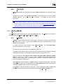
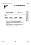
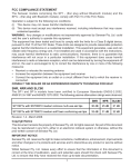
&$/,%5$7,217(679(5,),&$7,217(675816&5((1
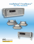
The run screen is active when a Calibration Test or Verification Test is running.
The screen can be scaled by dragging its corners or positioned by dragging its title
bar at any time while a test is running.
The run screen provides a convenient display of the test molbloc flow conditions
(Reynolds number, upstream pressure, downstream pressure, average temperature)
as well as the current program status.
The round red/green indicator in the upper left hand corner is the ready/not
ready indicator. The indicator is green when the test molbloc/molbox flow becomes
ready by meeting the molbox stability criterion (see the molbox Operation and
Maintenance Manual, ready/not ready section).
The blue status panel tracks the current test point and averaging information.
The <Current> display indicates the point number, within the overall test, of the point
that is being taken or that will be taken when the Take Point icon is clicked.
The <Avg Time> display indicates the molbox averaging time for a point. The time
counts down to zero when CalTool is taking a point. The bottom line of the panel
indicates the current program status: <IDLE> when a test is NOT running;
<RUNNING> when a test is running but a point is NOT being taken; <AVERAGING>
while counting down the averaging period when taking a point; <DATA ENTRY>
when the user must make an entry; <TARE MODE> when the CalTool tare screen is
active and the user has the ability to tare the test or reference molbox.
Figure 2. Calibration Test/Verification Test Run Screen
Page 17
©1999 DH Instruments, Inc.
CalTool™ for molbloc™ User’s Manual
5817(67722/%$5
The Run Test Toolbar is used to control a test. The Toolbar is active when a
Calibration or Verification Test is running. Clicking the Run Test Toolbar icons
executes various test functions. The Run Test Toolbar icons include: Take Point,
Abort Current Point, Repeat Test Point, Display Graph, End Test, Abort Test, Average
Time, Tare.
Table 1. Tools Available on the Run Test Toolbar
ICON
Take Point
DESCRIPTION
Starts the Take Point sequence to take a test point in a Calibration or Verification
Test. The Take Point sequence includes: start molbox reading averaging cycle and
average over time period, log average molbox reading to data file, acquire reference
mass flow standard reading by manual entry or automatically. Pressing the ENTER
on the PC key as a shortcut to this function.
The averaging time is determined by the <Avg Time> field on the toolbar.
Abort Point
Repeat Point
Interrupts the Take Point process and aborts the current point. Press ESC on the PC
as a shortcut to this feature.
Used to retake a test point. Decrements the current point back once each time it is
clicked. If clicked several times to go back more than one point, all the points must be
retaken.
The <Repeat Point> icon is not active while taking a point.
Tare molbox
Starts the Tare molbox sequence to tare the test or reference molbox. After selecting
which molbox to tare and whether to tare on the upstream or downstream molbloc
port, the <Tare molbox> window displays. Pressing the <Tare> button causes the
molbox to execute the tare function and activate the new tare(s). If an invalid tare
occurs, repeat the process. When taring is complete, use the close control box in the
top right hand corner to close the tare display and return to the <Run Screen>. See
the molbox Operation and Maintenance Manual for complete information on taring and
its importance to good measurements.
The <Tare molbox> icon is not active while taking a point.
Display Graph
End Test
©1999 DH Instruments, Inc.
Cause the <Plots> window to be displayed with a real time % of reading error plot of
the test that is running.
Used for a normal test ending after execution of the last data point. After confirmation,
causes the <Save Data File As> window to be presented. Accept the default data file
name and path or edit and select <Save> to save the data file. If the test was a
Calibration Test, operation proceeds to the <Calculation/Activation> screen.
Page 18
CalTool™ for molbloc™ User’s Manual
Table 1. Tools Available on the Run Test Toolbar (Continued)
ICON
Abort Test
Avg Time
DESCRIPTION
Used to completely abort a Calibration or Verification Test without saving data. After
confirmation, causes test execution to stop and status to go to <IDLE>.
Enter the time in seconds over which molbox readings are to be averaged. The
minimum averaging time is 5 seconds and the maximum is 9999 seconds. The
averaging time setting affects both the test and reference molbox if the reference
mass flow standard is a molbox.
(Text Entry)
The averaging time can be edited between points while a test is running.
>9(5,),&$7,217(67@
[Verification Test] is used to run a simple comparison of a test molbloc and a
reference standard that does not end in calculation and activation of new molbloc
calibration coefficients.
A Verification Test is identical to a Calibration Test in both setup and operation (see
Section 4.1.1) but the Verification Test does not go directly to Calculation/Activation; the test
ends with a display message of the maximum % Reading error and the default name of the
resulting data file is *(Verify)*.dat. Calibration Test and Verification Test data files are identical
in structure. A Verification Test data file can be used with the Calculation function to
determine new molbloc calibration coefficients and predict as left data if desired (see
Section 4.1.3).
The Verification Test is normally used after a calibration to verify the predicted as left data.
It is also used for routine comparisons of molblocs and a reference standard.
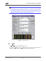
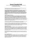
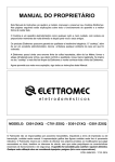
>&$/&8/$7,21@
[Calculation] is used to calculate new molbloc coefficients and predicted as left data from a
data file (*.dat), for example a data file that has been created or edited manually or a
Verification Test data file. This function also allows the results of the calculation to be
activated by writing to the molbloc and creating a result file (*.res).
When [Calculation] is selected, the file on which calculations are to be performed must
be specified. The <Select Data File> window is presented. Select the desired data file.
The Calculation function requires that valid communications with a molbox be set up and that
the molbloc identified in the *.dat file selected is connected to the molbox. If the information in
the data file, including the as received molbloc calibration coefficients for the gas specified in
the data file, does not match the molbloc that is connected, the calculate process is aborted.
This feature is to assure that calculations are being performed for the correct molbloc with the
correct calibration coefficients. If the molbloc coefficients are not the coefficients that were
active when the data in the data file was taken, the calculation of the new calibration
coefficients and as left data would not be valid.
Page 19
©1999 DH Instruments, Inc.
CalTool™ for molbloc™ User’s Manual
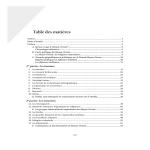
If the information contained in the selected data file matches the current molbloc, CalTool
opens the <Calculation/Activation> screen and calculates new (as left) molbloc calibration
coefficients for the test gas and predicted as left data. The as left data is the as received data
recalculated using the new molbloc calibration coefficients. At this point, no changes have
been made to the molbloc. To make changes to the molbloc, <Activate Calibration> must
be selected.
Click <Activate Calibration> to cause the new (as left) calibration coefficients for the test gas
to be written to the molbloc. CalTool will again verify the actual molbloc information with the
information stored in the data file. If these do not match, the calibration cannot be activated.
If they do match, the new calibration coefficients are written to the molbloc and the <Save
Result File As> window is presented. Only the calibration coefficients relating to the gas
specified in the *.dat file are adjusted, no other molbloc information is adjusted.
<Calculate> is available to cause CalTool to recalculate, for example if an error occurred
during the original calculation.
Figure 3. Calculation/Activation Screen
>(;,7@
[Exit] is used to close the CalTool program.
©1999 DH Instruments, Inc.
Page 20
CalTool™ for molbloc™ User’s Manual
> 6(783@0(18
The [Setup] menu offers selections to set up communications interfaces with the test and the
reference and to select the test gas with which tests are run. The [Setup] menu includes the following
selections: [Interface] and [Test Gas].
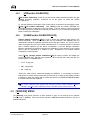
>,17(5)$&(@
[Interface] is used to set up the interface with the test molbox and the reference mass
flow standard. Many CalTool functions require a valid interface with a test molbox.
To set up CalTool communication interfaces, select [Setup], [Interface]. The <Interface
Setup> window is presented. In the <Device> selection box, select <Test molbox> to set up
the interface to the test molbox or <Reference> to set up the interface to the reference.
The current interface for the selected device is displayed in the <Remote Interface> box.
The drop down list includes the three interface choices that CalTool supports: <RS232>,
<IEEE-488> and <None>. <None> is only available for reference since a remote interface
with a test molbox is required. <RS232>, <IEEE-488> are apply for the reference only if the
reference is a molbox. CalTool does not support remote communications with references
other than a molbox.
If <RS232> is selected, the com port and port settings can be changed by clicking any of the
RS232 settings fields and making the desired selections on the RS232 setup form.
Default molbox COM1 settings are 2400, E, 7, 1.
If <IEEE-488> is selected, the IEEE-488 address of the molbox must be specified in the
field provided. The IEEE-488 Card in the PC must be selected in drop down list in the
<IEEE-488> selection box at the bottom of the form. The IEEE-488 card must be set up with
default addresses and 32 bit drivers for a Windows based 32 bit operating systems.
After a device interface is modified, click <Accept> so the value is updated in memory.
If <Accept> is not clicked, the interface value will not be saved.
<Communications Test> causes CalTool to send a test command to the molbox.
The detection status will display after the command is sent.
Select <Close> to exit the interface setup form.
Page 21
©1999 DH Instruments, Inc.
CalTool™ for molbloc™ User’s Manual
Figure 4. Interface Setup Window
Figure 5. Interface Setup Window, RS232 Settings
©1999 DH Instruments, Inc.
Page 22
CalTool™ for molbloc™ User’s Manual
>7(67*$6@
[Test Gas] specifies the gas species for which CalTool Calibration and Verification Tests
are run.
To select the test gas, select [Setup], [Test Gas]. A drop down menu of the test gases
available appears. The current test gas is checked. To change test gas, click the
desired gas.
>RO ^O]^ QK] VS]^ K`KSVKLVO SX -KV>YYV S] ^RO MYWZVO^O VS]^ YP WYVLYb ]_ZZY\^ON QK]O] K^ ^RO
^SWO^RO`O\]SYXYP-KV>YYVaK]\OVOK]ON3PcY_\`O\]SYXYP-KV>YYVNYO]XY^SXMV_NOK^O]^QK]
^RK^ S] K`KSVKLVO YX ^RO WYVLYb cY_ K\O _]SXQ Y\ `SMO `O\]K `S]S^ aaaNRSX]^\_WOX^]MYW ^Y
NYaXVYKNKXOaO\`O\]SYXYP-KV>YYVKXNY\WYVLYbOWLONNON]YP^aK\O
> '$7$@0(18
The [Data] menu offers various tools to work with CalTool data files. The [Data] menu includes the
following selections: [Create], [Edit], [Plot], [Print] and [View].
>&5($7(@
[Create] is used to create a data file (*.dat) manually. This option is useful to create a data file
from data taken at a time or place when CalTool with remote communications to a test
molbox were not available.
To create a data file (*.dat) manually, select [Data], [Create].
window is presented. Fill out the form.
The <Test Data Entry>
The Test Gas may be selected from the <Gas> drop down list.
The molbloc serial number must be correct as it will be verified and must match the connected
molbloc when the data file is used with the Calculate function (see Section 4.1.3).
In the test data grid, the reference flow, molbloc flow and molbloc Reynolds number
must be entered for a minimum of three points. CalTool automatically calculates the
difference and % reading error. 0 should not be included as a reference flow point as this
results in an invalid % reading error.
Select [Save] to save the data file. CalTool checks for invalid or missing data. Once valid
data has been entered into all required fields, the <Save Data File As> window is presented.
Accept the default file name and path or edit as desired.
Use [Clear] to erase all data from the entry form. This is useful when creating multiple data
files to get a clean form after each save without re-selecting the [Data], [Create] option.
Page 23
©1999 DH Instruments, Inc.
CalTool™ for molbloc™ User’s Manual
7KX_KV NK^K PSVO] NY XY^ MYX^KSX ^RO K] \OMOS`ON WYVLVYM MKVSL\K^SYX MYOPPSMSOX^] ]Y -KV>YYV
MKXXY^ `O\SPc ^ROW Z\SY\ ^Y KM^S`K^SXQ K MKVSL\K^SYX 0Y\ ^RS] \OK]YX aROX _]SXQ WKX_KVVc
M\OK^ON NK^K PSVO] ^Y KM^S`K^O KMKVSL\K^SYXS^S]M\S^SMKV^YK]]_\O^RK^^ROWYVLVYMRK]^RO
]KWOMKVSL\K^SYXMYOPPSMSOX^]N_\SXQMKVSL\K^SYXMKVM_VK^SYXKXNKM^S`K^SYXK]S^NSNN_\SXQ^RO
KM^_KV NK^K QK^RO\SXQ Z\YMO]] 0KSV_\O ^Y K]]_\O MYX]S]^OXMc S] VSUOVc ^Y \O]_V^ SX SX`KVSN
MKVSL\K^SYX]]SXMO-KV>YYVaSVVLO_]SXQSXMY\\OM^NK^KSXS^]MKVM_VK^SYX]
Figure 6. Test Data Entry Form
>(',7@
Use [Data], [Edit] to edit an existing data file (*.dat).
The operation of [Edit] is identical to [Create] except that an existing data file is selected and
loaded into the editor instead of starting from a blank form (see Section 4.3.1).
©1999 DH Instruments, Inc.
Page 24
CalTool™ for molbloc™ User’s Manual
>3/27@
[Plot] allows the CalTool % of reading error plot for an existing data (*.dat) or result (*.res) file
to be viewed.
To view a plot select [Data], [Plot]. Then click <Result File> or <Data File> to specify the
type of file to be plotted. The <Select File> window is presented. Select the desired file and
click <Open>.
The plot can be printed using [Data], [Print] or the <Print> toolbar option (see Section 4.3.4).
% of reading error is calculated following ((test-reference)/reference*100).
:VY^] YP \O]_V^ PSVO] \O] SXMV_NO LY^R ^RO K] \OMOS`ON KXN K] VOP^ NK^K YP \OKNSXQ
O\\Y\ZVY^]
>35,17@
[Print] allows a data file (*.dat), result file (*.res), plot or other text displays to be printed to the
selected Windows printer.
To print, select [Data], [Print]. Then click the desired item to be printed from the drop
down list. If <Result File> or <Data File> is selected, the file to print must be selected from a
<Select File> window.
[Data], [Print], <Current Text Display> prints the contents of any open test display, for
example a formatted result file or a molbloc calibration record. This function is useful for
maintaining hard copy records of CalTool information. The toolbar print option on the text
viewer is a shortcut to this function.
>9,(:@
[View] allows result (*.res) and data (*.dat) files to be viewed within CalTool.
After selecting [Data], [View] select <Result File> or <Data File> to view the unformatted,
comma delimited file. Select <Formatted Result File> or <Formatted Data File> to view a
file in a report style format that is more readable than the standard comma delimited format.
A print option on the viewer can be used to print the text display.
Page 25
©1999 DH Instruments, Inc.
CalTool™ for molbloc™ User’s Manual
> 722/6@0(18
The [Tools] menu offers various tools to support the calibration and adjustment of molblocs
with CalTool. The [Tools] menu includes the following selections: [Remove Gas Calibration],
[Restore molbloc], [Create Restore File] , [View molbloc Calibration] and [Change molbloc
Calibration Date].
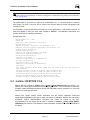
>5(029(*$6&$/,%5$7,21@
[Remove Gas Calibration] allows undesired gas calibrations to be removed individually from
a molbloc.
To remove the calibration of a gas from a molbloc, select [Tools], [Remove
Gas Calibration]. CalTool reads the contents of the connected molbloc through the
test molbox. If remote communication with a test molbox cannot be established, an error
message displays. The <Remove Gas> window is displayed including a listing of all the
gases (except N2) for which there are calibration coefficients on the connected molbloc.
Click the checkbox next to the gas or gases to be removed. Then click <Remove Gas>.
After confirmation, the calibration for the selected gas is removed from the molbloc.
>ROXS^\YQOX8QK]MKVSL\K^SYXMKXXY^LO\OWY`ONP\YWKWYVLVYM
Select [Exit] to close the <Remove Gas> window.
1
<OWY`SXQ K QK] P\YW K WYVLVYM S] XY^ K \O`O\]SLVO Z\YMO]] >Y \O]^Y\O ^RO QK] K XOa
MKVSL\K^SYXaSVVRK`O^YLO\_XK\O]^Y\OPSVOaSVVRK`O^YLOVYKNONPY\^ROWYVLVYM
Figure 7. Remove Gas Window
©1999 DH Instruments, Inc.
Page 26
CalTool™ for molbloc™ User’s Manual
>5(6725(PROEORF@
1
<O]^Y\O MRKXQO] ^RO MYWZVO^O WYVLVYM //:<97 PSVO SXMV_NSXQ ROKNO\ SXPY\WK^SYX KXN KVV
QK]MKVSL\K^SYX] <O]^Y\O WYVLVYM NYO] XY^ aY\U YX QK]O] SXNS`SN_KVVc S^ aY\U] aS^R ^RO
MYWZVO^O\O]^Y\OPSVOaRSMRMYX^KSX]+66WYVLVYMNK^K
[Restore molbloc] is used to restore a molbloc whose EEPROM has been corrupted or to
return a molbloc to a previous state. Using restore molbloc requires a valid restore file (*.brs).
Restore files are created using [Create restore file] (see Section 4.4.3). DHI technical
service maintains restore files for molblocs. However, these restore files will return the
molbloc to the calibration state last set by DHI. Any subsequent calibrations performed with
CalTool are be updated. For this reason it is important to create restore files when multiple
calibrations have been performed (see Section 3.3).
To load a restore file (*.brs) onto a molbloc, select [Tools], [Restore molbloc]. The <Select
molbloc Restore File> window is presented. Select the desired restore file (*.brs) and
select <Open>. CalTool requires several confirmations that the molbloc should really be
restored with the identified restore file.
Following the restore operation, [View molbloc Calibration] can be used to view the
information on the molbloc.
>RO<O]^Y\OYZ^SYX]RY_VNYXVcLO_]ONaROXKL]YV_^OVcXOMO]]K\c=c]^OWK^SM\O]^Y\SXQYP
^ROWYVLVYMS]XY^\OMYWWOXNON
>&5($7(5(6725(),/(@
[Create Restore File] is used to create a molbloc restore file (*.brs). A molbloc restore file is
a copy of the complete molbloc EEPROM contents that can be downloaded to the molbloc
EEPROM using [Restore molbloc] (see Section 4.4.2).
To create a molbloc restore file (*.brs), select [Tools], [Create Restore File]. After CalTool
reads the molbloc contents through the test molbox, the <Save molbloc Restore File As>
window is presented. Accept file name and path or edit it if desired. Then select [Save] to
create the restore file.
3PKXcO\\Y\]YMM_\aRSVOK\O]^Y\OPSVOS]LOSXQM\OK^ONWKUO]_\O^ROPSVOS]NOVO^ONKXN\O^\c
-\OK^SXQ K \O]^Y\O PSVO NYO] XY^ WYNSPc KXc YP ^RO WYVLVYM //:<97 MYX^OX^] S^ YXVc
]K`O]^ROW
Page 27
©1999 DH Instruments, Inc.
CalTool™ for molbloc™ User’s Manual
>9,(:PROEORF&$/,%5$7,21@
[View molbloc Calibration] is used to view the current molbloc header information and gas
CalTool accessible calibration coefficients for all the gases for which the molbloc
has calibrations.
To view the calibration information of the molbloc that is connected to the test molbox, select
[Tools], [View molbloc Calibration]. After CalTool reads the molbloc EEPROM, the
EEPROM information is displayed on the text display. The view option is a good check point
for molblocs that have recently been restored (see Section 3.3) or to determine the gases for
which a molbloc has calibrations.
>&+$1*(PROEORF&$/,%5$7,21'$7(@
[Change molbloc Calibration Date] is used to change the calibration date stored in the
molbloc EEPROM. Since each molbloc has only one calibration date, CalTool does not
automatically change the calibration date each time a new gas is added. It is up to the user to
define the purpose and use of the molbloc calibration date. It is common practice to allow this
date to always represent the last factory re-calibration or the last Nitrogen calibration.
Nitrogen calibrations are significant because this calibration is used internally by the molbox
when a gas not calibrated on a molbloc is used. Regardless of the method selected
consistency is most important.
Select [Tools], [Change molbloc Calibration Date] to read the molbloc and display the
current calibration date. Edit the date as desired. When entering and viewing the date, the
format must be YYYYMMDD where:
•
YYYY: 4 digit year
•
MM: 2 digit month
•
DD: 2 digit day
January 23, 1999 must be entered and displays as 19990123. It is necessary to include a
leading zero for month and day values that are less than 10 to insure the field always contains
8 characters. When the molbloc has an invalid date stored in the EEPROM, CalTool displays
the default calibration date 19800101.
>RO WYVLVYM MKVSL\K^SYX NK^O NS]ZVKcON KXN MRKXQON Lc E-RKXQO WYVLVYM -KVSL\K^SYX .K^OG S]
SXMV_NONSX^ROE@SOaWYVLVYM-KVSL\K^SYXGPOK^_\ONK^KPSVO]NK^KXN\O]_V^PSVO]\O]
> :,1'2:@0(18
The [Window] menu allows selection of which window to place on top among all the windows
currently open in CalTool. Each new window opened in CalTool automatically adds to the list of
available selections.
©1999 DH Instruments, Inc.
Page 28
CalTool™ for molbloc™ User’s Manual
- +6 > 996 0 36/ > C:/=
+8. - 2+<+->/<3=>3-= ,1752'8&7,21
CalTool for molbox creates and manipulates three different types of files which are detailed in
Sections 5.2 through 5.4. These include:
•
Data Files (*.dat): Files into which CalTool logs information from Calibration and Verification
Tests (see Section 4.1.1).
•
Result Files (*.res): File created from a data file after a calibration has been activated (see
Section 4.1.3). Includes the as left data calculated from the as received data (results).
•
Restore Files (*.brs): Copies of the complete information contained in a molbloc EEPROM (see
Section 3.3).
' $ 7 $ ) , / (
Data files are the files created by CalTool to store the information from a Calibration or
Verification Test.
The default data file name is “molbloc sn NNNN (Verify) GGGG.dat” where:
•
molbloc sn: file label
•
NNNN: the molbloc serial number
•
(Verify): label present only on files created by a Verification Test to distinguish them from a
Calibration Test
•
GGGG: the calibration gas used in the Calibration or Verification Test
•
.dat: automatic file extension of a data file
Page 29
©1999 DH Instruments, Inc.
CalTool™ for molbloc™ User’s Manual
The default path for a data file is “CalTool for molbloc/Data/*.dat. If a new file location is selected
while saving, all data (*.dat) files will be saved to the selected path by default until another path
selection is made.
The data file is comma delimited for easy use in other applications. If a data file is created manually,
the Calibration Date, CG and Beta values will be blank. In this case, it is critical that the molbloc have
the same calibration coefficients during calibration activation as it did during the actual data
gathering process. Failure to follow this step may result in large discrepancies between the predicted
as left molbloc error and the actual as left error. If the manually created data file is used to activate a
calibration, the current molbloc coefficients are automatically written to the data file.
In the sample data file, all fields that appear in italics are fixed fields created by CalTool.
The calibration instruments and process determine the remaining information.
Sample data file:
molbloc SN, 1281
molbloc Range, 100.0 sccm
Cal Date, Cg, Beta
19991116 ,2.8248E-16,-3.918E-05
molbox Model, molbox1 Ver4.02c
molbox SN, 407
Test Gas, N2
Test Pressure, 274 kPaa, sccm
Reference SN, molbox 430 molbloc 723
Reference ID, Station #6
Reference Model, molbox1 Ver4.02c
Test Data
Ref Flow, molbloc Flow, molbloc Re, Diff, %Rdg Err
14.3762, 13.0663, 21.24,-1.3099,-9.112
23.8636, 21.7522, 35.36,-2.1114,-8.848
42.0102, 38.2995, 62.26,-3.7107,-8.833
69.9469, 63.788, 103.7,-6.1589,-8.805
108.249, 98.7883, 160.59,-9.4607,-8.740
5(68/7),/(
A result file is created by CalTool from a data file (see Section 5.2) and the results of the calculation
function when a calibration is activated (see Section 4.1.3). The result file is identical to the data file
but it contains additional information including the calculated as left molbloc calibration coefficients and
as left test data for the test gas. The result file also has a different file extension (*.res).
The default result file name is “molbloc sn NNNN GGGG.res” where:
•
molbloc sn: file label
•
NNNN: the molbloc serial number
•
GGGG: the calibration gas used in the Calibration or Verification Test from which the result file
was created
•
.res: automatic file extension of a result file
©1999 DH Instruments, Inc.
Page 30
CalTool™ for molbloc™ User’s Manual
3P^RO\O]_V^PSVOS]M\OK^ONP\YWKNK^PSVO\O]_V^SXQP\YWK@O\SPSMK^SYX>O]^@O\SPcS]89>SXMV_NONSX
^RO\O]PSVOXKWO
The default path for a result file is “CalTool for molbloc/Data/*.res. If a new file location is selected
while saving, all result (*.res) files will be saved to the selected path by default until another path
selection is made.
The result file is a comma delimited file for easy use in other applications. In the sample result file, all
fields that appear in italics are fixed fields created by CalTool. The calibration instruments and
process determine the remaining information.
Sample Result File:
Wed November 24, 1999
09:58 AM
Test Gas, Test Pressure, Flow Unit
N2,274 kPaa, sccm
Reference Model, Reference ID, Reference SN
molbox1 Ver4.02c,Station #6,molbox 430 molbloc 723
molbox Model, molbox SN
molbox1 Ver4.02c,407
molbloc SN, Nominal Range, Cal Mode
1281,100.0 sccm,Recalibration
As Received Calibration
Cal Date, Cg, Beta
19991116,3.104707E-16,-5.848963E-05
As Left Calibration
Activation Date, Cg, Beta
1991116,3.101733E-16,-4.422007E-05
Test Data
Ref. Flow, molbloc Flow, diff, %Rdg Err, As Left flow, As Left Diff, As
Left %Rdg Err
108.131,107.963,-0.168,-0.155,108.1305,-0.0005,0.000
78.7568,78.6797,-0.0771,-0.098,78.7478,-0.009,-0.011
61.9754,61.9475,-0.0279,-0.045,61.9771,0.0017,0.003
43.1317,43.141,0.0093,0.022,43.1428,0.0111,0.026
20.9995,21.0057,0.0062,0.030,20.996,-0.0035,-0.017
PROEORF5(6725(),/(
Restore files are created by CalTool using [Tools], [Create Restore File] (see Section 3.3).
Restore files contain all the information from a molbloc EEPROM. They are intended to restore the
complete molbloc EEPROM information should the EEPROM become corrupted or to return the
molbloc to a known previous state.
Restore files contain molbloc header information and the molbloc calibration coefficients
manipulated by CalTool for each gas for which the molbloc is calibrated. Restore files also contain
confidential molbloc characterization information that cannot be viewed by the user.
Any modifications to the restore file will make it unusable to CalTool. [Tools], [View molbloc
Calibration] (see Section 4.4.4) allows the public information contained in a molbloc EEPROM to
be viewed.
Page 31
©1999 DH Instruments, Inc.
CalTool™ for molbloc™ User’s Manual
The default restore file name is “molbloc sn NNNN Restore.brs” where:
•
molbloc sn: file label
•
NNNN: the molbloc serial number
•
Restore: label to identify the file as a restore file
•
.brs: automatic file extension of a molbloc restore file
The default path for a molbloc restore file is “CalTool for molbloc/Restore/*.brs. If a new file location is
selected while saving, all restore (*.brs) files will be saved to the selected path by default until another
path selection is made.
©1999 DH Instruments, Inc.
Page 32
CalTool™ for molbloc™ User’s Manual
WYVLVYM89738+6
069A<+81/=3D/
./=318+>398=+8.
+->?+6:</==?</
<+81/=A3>2@+<39?=
1+=/=
PROEORF6,=($1'5$1*('(6,*1$7,216
Until mid-1999, molblocs were always identified by “Range”. The “Range” is the molbloc’s nominal
full scale flow in Nitrogen (N2) at an operating pressure of 250 kPa. Actual molbloc ranges change
with operating pressure and calibration gas (see the molbox Operation and Maintenance Manual,
Flow Measurement Specifications). Since mid-1999, molblocs have been designated by size with a
sizing code.
On molbloc EPROM’s, the molbloc is still identified by its nominal range rather than by its size,
therefore, CalTool identifies molblocs by their nominal ranges. molbloc size and range designation
correspondence are given in Table 2.
Page 33
©1999 DH Instruments, Inc.
CalTool™ for molbloc™ User’s Manual
Table 2. molbloc Size and Nominal Range Designations
molbloc “NOMINAL
RANGE” DESIGNATION
molbloc SIZE
DESIGNATION
10 sccm
1E1
50 sccm
5E1
100 sccm
1E2
200 sccm
2E2
500 sccm
5E2
1 slm
1E3
5 slm
5E3
10 slm
1E4
30 slm
3E4
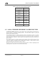
P ROEORF35(6685('(3(1'(17&$/,%5$7,217<3(6
All CalTool for molbloc calibrations are of the “Single P” type, meaning that they are performed at a
specific upstream or downstream operating pressure. The valid molbloc range for a given gas
depends on the calibration pressure.
If the calibration pressure is a molbloc downstream pressure of atmospheric pressure or a molbloc
upstream pressure between 250 and 325 kPa absolute (36 and 48 psia), the molbloc is considered to
have a LOW pressure calibration. molbloc ranges for various gases with low pressure calibrations are
given in Table 3.
If the calibration pressure is a molbloc upstream pressure between 325 and 525 kPa absolute (47 and
76 psia), the molbloc is considered to have a HIGH pressure calibration. molbloc ranges for various
gases with HIGH pressure calibrations are given in Table 4.
Extending the molbloc range beyond the ranges specified in Table 3 or Table 4, depending on their
operating pressure, may result in out of tolerance measurements.
©1999 DH Instruments, Inc.
Page 34
CalTool™ for molbloc™ User’s Manual
Table 3. molbloc Ranges with Low Pressure Calibrations
A bold value indicates that the maximum flow is limited by the maximum Reynolds number value of
1 200 which is reached before the normal differential pressure range is reached. In that case, the
second value gives the minimum flow for which measurement uncertainty (accuracy) is a % of the
measured value. With the microrange option, this value is divided by 10 (see molbloc Flow
Measurement Specifications in the molbox Operation and Maintenance Manual).
Page 35
©1999 DH Instruments, Inc.
CalTool™ for molbloc™ User’s Manual
Table 4. molbloc Ranges with High Pressure Calibrations
A bold value indicates that the maximum flow is limited by the maximum Reynolds number value of
1 200 which is reached before the normal differential pressure range is reached. In that case, the
second value gives the minimum flow for which measurement uncertainty (accuracy) is a % of the
measured value. With the microrange option, this value is divided by 10 (see molbloc Flow
Measurement Specifications in the molbox Operation and Maintenance Manual).
Where there is no value in the table (-), this indicates that the maximum Reynolds number is reached
before the differential pressures reaches 5 kPa, therefore calibration with that gas is not useful.
©1999 DH Instruments, Inc.
Page 36
CalTool™ for molbloc™ User’s Manual
! 1 69==+<C % Reading Error
The disagreement of the DUT and the reference expressed as a % of the
reference reading. ((DUT – reference)/reference) * 100.
Absolute
As in “absolute pressure”. Pressure expressed relative to vacuum.
β (Beta)
One of the molbloc calibration coefficients manipulated by CalTool for molbloc.
The slope of the variation of C G with Reynolds number.
CG(re)
One of the molbloc calibration coefficients manipulated by CalTool for molbloc.
Geometry of the molbloc flow path and Reynolds number dependence.
Calibration Gas
(Test Gas)
The gas species flowed in a calibration or verification test. The gas with which
the molbloc is being calibrated.
Calibration Test
A test run by CalTool for molbloc that collects readings from a molbloc and a
mass flow standard, stores the readings in a data file (*.dat) and goes directly to
the calculate and activate calibration functions at the end of the test. Calibration
tests are run with the intention of calculating new molbloc calibration coefficients.
Downstream
Location of point A relative to point B in a flow system in which point A is at a
different location in the direction of the flow. For example, the downstream
molbloc pressure port is downstream relative to the upstream pressure port
because it is at a different location from the upstream port in the direction of the
flow.
DUT
Device Under Test. The device being tested or calibrated.
Full Mod Calibration
A molbloc calibration option which is valid over a range of operating pressure.
Fixed Measurement
Cycle Flow Standard
A mass flow standard whose operating principle requires measurement of volume
or pressure change over a period of time.
FS
Abbreviation of "full scale". The full scale value is the maximum value or the
span of a measurement range. Limits and specifications are often expressed as
% FS.
Page 37
©1999 DH Instruments, Inc.
CalTool™ for molbloc™ User’s Manual
Gauge
As in “gauge pressure”. Pressure expressed relative to atmospheric pressure.
K Factor
A factor representing the relationship between the process gas and a surrogate
gas for a DUT.
Operating Pressure
The average pressure at which the molbloc is operated (average of upstream and
downstream pressure) or, if the molbloc pressure is held constant by an upstream
or downstream regulator, the value of the constant pressure.
Process Gas
The gas for which a device under test is to be characterized or calibrated. The
gas that will actually flow in the device under test when it is used in a process.
PRT
Platinum Resistance Thermometer. The element used in molblocs to measure
temperature.
Psia
Pressure unit “pounds per square inch absolute”. Pressure expressed relative to
vacuum.
Psig
Pressure unit “pounds per square inch gauge”. Pressure expressed relative to
atmospheric pressure.
Rate
A molbox DISPLAY function in which the current rate of change of the flow in flow
units/second is displayed. A measure of stability of the flow used by the molbox
to make the ready/not ready determination. See also Stability Limit.
Ready/Not Ready
Indication of when flow is stable within the stability limit. See also Stability Limit.
Reynolds Number
A ratio of the inertia forces to the viscous forces in a flowing fluid. This
dimensionless number, which is dependent on fluid viscosity, density, velocity
and length of the flow field, is often used to predict a boundary point between
laminar and turbulent flow regimes.
RPT
Reference Pressure Transducer. The pressure transducers used in molbox1 and
molbox RFM are referred to as RPTs.
Single P Calibration
A molbloc calibration option which is valid at a single specified operating
pressure.
Stability Limit
A limit expressed in units of flow per second (e.g., sccm/second). The stability
limit is used as the Ready/Not Ready criterion Ready (<*>) if rate is less than
stability limit, Not Ready (<↑> or <↓>) if rate is greater than stability limit. See
also Rate.
©1999 DH Instruments, Inc.
Page 38
CalTool™ for molbloc™ User’s Manual
Surrogate Gas
A gas whose behavior, from the standpoint of a device under test, is similar to the
process gas for which the device is to be characterized and used. A surrogate
gas is often used in calibration and testing when the process gas cannot be used
for safety or cost reasons.
Test Pressure
The pressure at which the molbloc is being calibrated and will be used. To use
CalTool properly, the test pressure must be a constant upstream or downstream
value within the limits of the molbloc pressure dependent calibration options. See
the molbloc pressure dependent calibration types and ranges in Section 6.
Upstream
Location of point A relative to point B in a flow system in which point A is at a
different location in the opposite direction of the flow. For example, the upstream
molbloc pressure port is upstream relative to the downstream pressure port
because it is at a different location from the downstream port in the opposite
direction of the flow.
Verification Test
A test run by CalTool for molbloc that compares readings from a molbloc and a
mass flow standard and creates a data file (*.dat) but does not go directly to the
calculate and active calibration functions at the end of the test. Verification tests
are run with the intention of verifying a molbloc calibration.
Volumetrically Based
Mass Flow Units
Mass flow units of measure that are based on the quantity of gas that occupies a
fixed volume under reference pressure and temperature conditions.
Page 39
©1999 DH Instruments, Inc.
CalTool™ for molbloc™ User’s Manual
89>/=
©1999 DH Instruments, Inc.
Page 40