1
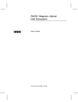
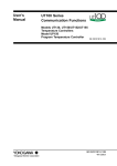
MD400 Scanner
Pocket Service Guide
Order Number EK-MD400-MC-001
Digital Equipment Corporation
May 1991
The information in this document is subject to change
without notice and should not be construed as a
commitment by Digital Equipment Corporation. Digital
Equipment Corporation assumes no responsibility for
any errors that may appear in this document.
The software described in this document is furnished
under a license and may be used or copied only in
accordance with the terms of such license.
No responsibility is assumed for the use or reliability of
software on equipment that is not supplied by Digital
Equipment Corporation or its affiliated companies.
Restricted Rights: Use, duplication, or disclosure by
the U. S. Government is subject to restrictions as set
forth in subparagraph ( c ) ( 1 ) ( ii ) of the Rights in
Technical Data and Computer Software clause at DFARS
252.227–7013.
Copyright © Digital Equipment Corporation 1991
Digital Equipment Corporation
All Rights Reserved.
Printed in U.S.A.
DECimage, DECstation, ULTRIX, VAXstation, VMS, and
the DIGITAL logo are trademarks of Digital Equipment
Corporation.
MS-DOS is a trademark of Microsoft Corporation.
This document was prepared and published by
Educational Services Development and Publishing,
Digital Equipment Corporation.
Contents
v
About This Guide
1
INTRODUCTION . . . . . . . . . . .
1.1
General . . . . . . . . . . . . . . . .
1.2
Hardware Options . . . . . . . .
1.3
Software Options . . . . . . . . .
1.4
Product Documents . . . . . . .
1.5
System Configurations . . . . .
1.5.1
PC Environment (Parallel
Interface) . . . . . . . . . . . . .
1.5.2
VAX Environment (SCSI
Interface) . . . . . . . . . . . . .
.
.
.
.
.
.
1
1
1
2
2
3
.
3
.
3
...
...
...
4
4
5
...
8
2
2.1
2.2
2.3
INSTALLING THE SYSTEM
Before Installation . . . . . .
Installation . . . . . . . . . . .
Post-Installation Checks Verification . . . . . . . . . . . .
3
3.1
3.2
3.3
3.4
3.5
TROUBLESHOOTING . . . . . .
VAXstation Software . . . . .
PC Software . . . . . . . . . . . .
Shading Correction . . . . . .
Hardware Service Strategy
Service Features . . . . . . . . .
.
.
.
.
.
.
.
.
.
.
.
.
8
8
8
9
9
10
iii
iv Contents
3.6
3.7
3.8
Self-Tests . . . . . . . . . . . . . . . .
ADF Faults . . . . . . . . . . . . . .
Unit Diagnostics . . . . . . . . . .
10
12
12
4
SPARES LIST . . . . . . . . . . . . . .
16
5
5.1
5.2
TECHNICAL TIPS . . . . . . . . . . .
Voltage Selection . . . . . . . . . .
Limitations of SCSI
Configurations . . . . . . . . . . . .
17
17
6
FURTHER INFORMATION
AND HELP . . . . . . . . . . . . . . . .
18
18
Figures
1
2
DIP Switch Setting For Normal
Operation . . . . . . . . . . . . . . . . . .
DIP Switch Setting in
Diagnostic Mode . . . . . . . . . . . . .
7
13
Tables
1
2
3
4
5
6
7
8
9
10
11
Hardware Options . . . . . . . . .
Software Options . . . . . . . . . . .
Product Documents . . . . . . . . .
Physical Characteristics . . . . .
Indicators . . . . . . . . . . . . . . . . .
Indicator Displays . . . . . . . . . .
Diagnostics . . . . . . . . . . . . . . . .
Unit Diagnostics Tests . . . . . . .
FRU List . . . . . . . . . . . . . . . . .
MD40X-SK SCSI Interface Kit
FRUs . . . . . . . . . . . . . . . . . . . .
Power Cords . . . . . . . . . . . . . . .
.
.
.
.
.
.
.
.
.
1
2
2
5
7
11
13
15
16
.
.
16
17
About This Guide
This pocket service guide provides information for
installing and servicing the MD400 scanner.
If you have any comments about this document,
please contact CSSE Solent, for attention of
G. Georgiou @SBP.
v
MD400 Scanner Pocket Service Guide
1
1
INTRODUCTION
1.1 General
The MD400 scanner is a resale of the Ricoh IS50
Image scanner. It is available in 120 Volt and
220-240 Volt variants.
It has an embedded SCSI interface port for
connection to a VAXstation computer, and
a parallel interface port for connection to a
DECstation PC. You must use the appropriate
SCSI or PC interface kit option. The personal
computer (PC) interface kit includes the Ricoh
ISI-8 PC interface card which must be installed in
the DECstation backplane.
The Ricoh DF60 automatic document feeder (ADF)
is available as a separate option.
1.2 Hardware Options
The hardware options are shown in Table 1.
Table 1
Hardware Options
Vendor
Part
Number
Vendor
IS50 Image
scanner 120v
IS50
Ricoh
MD400A3
IS50 Image
scanner 220-240v
IS50
Ricoh
MD40XDF
DF60 Automatic
document Feeder
DF60
Ricoh
MD400BA
MD400-AA +
MD40X-DF
IS50+DF60
Ricoh
MD400B3
MD400-A3 +
MD40X-DF
IS50+DF60
Ricoh
MD40XSK
SCSI Interface Kit
(VAXstation)
-
-
MD40XPK
PC Interface Kit
(DECstation PC)
ISI-8
Ricoh
MD40XLA
Replacement Lamp
H2045018
Ricoh
Digital
Option
Description
MD400AA
2 MD400 Scanner Pocket Service Guide
1.3 Software Options
The software options are shown in Table 2.
Table 2
Software Options
Description
VAX
PC
Vendor
DECimage Scan
Software V2.1
Yes
No
Digital
ProImage V3.10
For Digital MD400
No
Yes
Software
Dynamics
GmbH
MS-Windows V3.0
No
Yes
Microsoft
MS-DOS V3.1 or
higher
No
Yes
Microsoft
1.4 Product Documents
The documents shown in Table 3 are available in
TIMABOX.
Table 3
Digital
Part
Number
Product Documents
Title
Order From
(available
July 1991)
EKMD400MC-001
MD400 Scanner Pocket
Service Guide
P&CS
Northboro
MA
EKMD400UG-001
MD400 Scanner User
Supplement
ESSB Galway
MD400 Scanner Pocket Service Guide
3
1.5 System Configurations
1.5.1 PC Environment (Parallel Interface)
•
•
Hardware
•
DECstation 220, 316, 320, 325, 425.
Minimum: 2Mbyte Memory, 20 Mbyte
hard disk, mouse, EGA video.
Must have a spare backplane slot for
interface card.
Interrupt Request, IRQ2 or IRQ3 must be
free.
•
MD400-AA for 120v
or
MD400-A3 for 220-240v operation.
•
MD40X-PK
Software
•
ProImage V3.10 For Digital MD400
scanner.
•
MS-Windows V3.0 or later.
•
MS-DOS V3.1 or higher.
1.5.2 VAX Environment (SCSI Interface)
•
Hardware
•
VAXstation 3100 Models 30, 38, 40, 48, 76.
Minimum 16Mbyte main memory.
•
MD400-AA for 120v
or
MD400-A3 for 220-240v operation .
•
MD40X-SK.
4 MD400 Scanner Pocket Service Guide
•
Software
•
2
DECimage Scan Software (DSS) V2.1.
INSTALLING THE SYSTEM
2.1 Before Installation
The MD400 hardware and software is customer
installable. Digital will install the option for an
additional charge.
Before attempting to install the scanner, identify
the following:
•
All system components for a supported
configuration are on site
•
A suitable location for siting the
scanner/system (Refer to the next paragraph)
•
A suitable location for unpacking the
equipment.
Check for the following when choosing a suitable
location to install the system:
•
Scanner shielded from direct sunlight at all
times of day
•
Scanner away from high temperature,
humidity and vibration
•
Scanner away from excessive dust or corrosive
gases
•
Power cord will reach the power outlet,
without causing obstruction
•
Interface cable will reach the computer,
without causing obstruction
•
Desk top flat, level, stable and can adequately
support weight and size of the scanner and the
computer (Refer to Table 4).
The physical characteristics of the scanner and the
ADF are shown in Table 4.
MD400 Scanner Pocket Service Guide
Table 4
5
Physical Characteristics
Characteristic
Value
Height
300 mm
625 mm with ADF in
highest position
Width
390 mm
Depth
610 mm, including space for
cables
Weight
Scanner: 12 Kg
ADF: 5 Kg
Temperature
5 to 35 °C
Humidity
30 to 85 %
Length of cables
supplied in SCSI
interface kit
1 metre
Length of cable
supplied in PC
Interface Kit
2 metres
Length of power cord
supplied with scanner
2.5 metres
2.2 Installation
1.
Take unopened cartons to the area previously
identified for unpacking.
2.
Check packaging for shipping damage and
report any damage found.
3.
Unpack and check for short shipments (refer
to IS50/DF60 User Manuals).
4.
Retain packing materials. These will be
needed for service.
5.
Place equipment in the location previously
prepared for installation.
6 MD400 Scanner Pocket Service Guide
6.
Read the installation procedures in the
IS50/DF60 User Manuals.
NOTE
The power cord is shipped as a separate
line item, not with the scanner (as shown
in the IS50 User Manual).
7.
VAXstation users should halt the system and
use the console command:>>> SHOW DEVICES
to display the current status of SCSI IDs.
Determine and note a suitable SCSI ID for
the scanner; an ID of zero is recommended if
available.
8.
Switch off the power to the system box and all
peripherals.
WARNING
Before connecting or disconnecting
interface cables, remove power from
the scanner, the host computer and any
other devices connected to the SCSI bus.
WARNING
A special interface cable is supplied in
the PC interface kit. Do not use any
other cable for this purpose as this may
severely damage equipment.
9.
Install the interface kit to connect the
computer to the scanner as follows:
•
VAXstation - I/F cables and terminator,
refer to the 3100 User Manual.
•
DECstation - I/F card and cable, refer to
the ISI-8 Installation Manual.
MD400 Scanner Pocket Service Guide
For
For
DECstation
VAXstation
off
on
1
2
3
4
0
off
1
on
0
1
6
7
8
1
1
1
SCSI ID 0
1
1
0
SCSI ID 1
1
0
1
SCSI ID 2
lamp on only when scanning 0
1
0
0
SCSI ID 3
lamp cycled to keep ready 1
0
1
1
SCSI ID 4
0
1
0
SCSI ID 5
0
0
1
SCSI ID 6 * DO NOT USE
0
0
0
SCSI ID 7 * DO NOT USE
5
6
7
1
8
7
2
3
4
5
normal operating mode 0
Unit Diagnostic mode 1
not used
SCSI I/F 0
Parallel I/F 1
* RESERVED FOR 3100
lo speed parallel I/O 0
INTERNAL DEVICES
hi speed parallel I/O 1
Figure 1
DIP Switch Setting For Normal
Operation
10. Set the DIP switch on the rear panel as shown
in Figure 1.
NOTE
Use DIP switches 6,7 & 8 to select the
SCSI ID previously noted.
11. Install the ADF if required (refer to DF60
User Manual).
CAUTION
Remember to unlock the carriage lock on
the scanner.
12. Power up the scanner and check the self-test
completes successfully. The indicators light as
shown in Table 5 for successful completion.
Table 5
Indicators
SCANNER
RED
GREEN
off
on
13. If indicators are lit as in step 12 the hardware
installation is complete. Go to step 15.
8 MD400 Scanner Pocket Service Guide
14. Switch the power off. Check that the
installation has been carried out correctly.
Repeat or check steps 8 to 12.
If there is still an error, refer to Section 3.
15. Install the software if required (refer to the
ProImage or DSS manuals).
2.3 Post-Installation Checks - Verification
When the hardware and software has been
installed, it is recommended that a document
is scanned to check the system is functioning
correctly. Beware that image defects in printed
hardcopy may be due to limitations of the printer
rather than the scanner.
If the performance of the printer is in doubt, use
a VDU output device to check the quality of a
scanned image. Ask the customer to perform the
scan, or refer to the DSS or ProImage Software
User Manuals for help.
Ask the customer to retain the original shipping
packaging on site. Explain that it is the user’s
responsibility to carry out preventive maintenance
and lamp replacement and point out these details
in the Users Manuals.
3
TROUBLESHOOTING
3.1 VAXstation Software
DECimage Scan Software (DSS) is a fully Digital
supported software product. Refer to the relevant
product service documentation.
3.2 PC Software
ProImage is supported directly by the vendor,
Software Dynamics GmbH. The vendor provides
a registration card which the user must complete
and return to the vendor. This permits the user
to contact the vendor by telephone or FAX and get
help with ProImage software:
MD400 Scanner Pocket Service Guide
9
SOFTWARE DYNAMICS GmbH (Germany)
Contacts : Mr Thomas Deharde
Mr Dick Dirks
Mrs Sharon Dirks
Phone: 49-0421/32 04 61
FAX : 49-0421/32 61 35
Business hours: 09.00 to 17.00
(local time) Monday to Friday
3.3 Shading Correction
If the symptoms are uneven shading, cycle the
power on/off and re-scan.
NOTE
It is necessary for the scanner power to be
periodically cycled in order for the correction
to be fully effective.
The MD400 incorporates shading correction to
compensate for the effects of:
•
Uneven illumination
•
Uneven sensitivity of CCD elements
•
Uneven lens characteristics
•
Effects of ageing.
The correction is done by using data stored in a
correction memory. Data is automatically acquired
in the correction memory on power-up, by reading
a plain white tape which is built into the scanner.
3.4 Hardware Service Strategy
Localise the fault using built-in tests and replace
the defective field replaceable unit (FRU). Refer to
Section 4 for the FRU list.
10 MD400 Scanner Pocket Service Guide
3.5 Service Features
•
Indicators: Red and Green on the scanner
front panel. Green on ADF. Each indicator can
show three conditions: on, off, blink.
•
DIP switches: Located on the rear panel (refer
to IS50 User Manual).
•
Built-in tests:
•
Self-tests
•
Unit diagnostics.
3.6 Self-Tests
The Self-Test is invoked at power-on. A lamp test
is performed during the time that the self-tests
are running; the indicators are switched on for
approximately 4 seconds.
If the lamp test fails, check the electrical supply
and follow the troubleshooting procedure in the
IS50 User Manual.
At completion of the self-tests or if an error is
detected during normal operation, the indicators
display the error as follows as shown in Table 6.
The indicator display are those at completion of
the self-tests or errors encountered during normal
operation.
MD400 Scanner Pocket Service Guide
Table 6
11
Indicator Displays
Indicators
RED
GREEN Description
OFF
ON
NO ERROR
ON
ON
Power/ROM/RAM error1
1.
Run unit diagnostic test 1.
ON
BLINK
Illumination error
1.
Cycle power, correct shading.
2.
Replace lamp.
3.
Cycle power to run self-test.
4.
Failing? Swap scanner.
BLINK
BLINK
Optical system error
1.
Cycle power, correct shading.
2.
Replace lamp.
3.
Cycle power to run self-test.
4.
Failing? Swap scanner.
1 This status also occurs during normal operation when
the scanner is ‘‘busy’’.
12 MD400 Scanner Pocket Service Guide
Table 6 (Cont.)
Indicator Displays
Indicators
RED
GREEN Description
ON
OFF
1.
Driving system error
Swap scanner.
BLINK
OFF
ADF residual paper error
1.
Remove paper inside ADF.
2.
Cycle power to run self-test.
3.
Run unit diagnostic test 4.
3.7 ADF Faults
You can check the operation of the ADF by loading
the ADF with paper and running unit diagnostics
test 4.
3.8 Unit Diagnostics
CAUTION
Note the DIP switch settings used for normal
operation before starting unit diagnostics.
Reset to the original setting when returning
the unit to normal operation.
Tests may be selected and controlled from the DIP
switches on the rear panel, as shown in Figure 2.
MD400 Scanner Pocket Service Guide
13
0 = off
1 = on
1
2
3
4
5
6
7
8
halt test 0
0
0
0
1
test 1 power test
run test 1
0
1
0
0
test 4 ADF operation test
normal operating mode 0
Unit Diagnostic
Unit Diagnostic mode 1
Figure 2
DIP Switch Setting in Diagnostic Mode
Running the unit diagnostics is described in
Table 7.
Table 7
Diagnostics
Step
Action
Indicators
RED
GREEN
1
Note the DIP
switch settings
used in normal
operation
2
Turn power switch
OFF
3
Set DIP switch
1 ON, to enable
diagnostic mode
4
Turn power switch
ON
BLINK
ON
5
Set DIP switch 1
OFF
BLINK
BLINK
6
Set DIP switch 1
ON
BLINK
BLINK
7
Select the test
number, using DIP
switches 5 to 8
8
Run selected test
by setting DIP
switch 3 ON
14 MD400 Scanner Pocket Service Guide
Table 7 (Cont.)
Step
Diagnostics
Action
9
To interpret error,
check the status
of the indicators
shown in Table 8
10
Set DIP switch
3 off to halt the
selected test
11
Wait for current
test to terminate
12
To run another
Unit test, go back
to step (7)
13
When Unit
Diagnostics
testing is complete,
switch off power
and RESET
DIP switches to
original positions
for normal
operation. After
repairing the
MD400 system,
perform the
Post-Installation
Checks
Indicators
RED
GREEN
ON
BLINK
MD400 Scanner Pocket Service Guide
Table 8
Unit Diagnostics Tests
Indicators
RED
15
Action
GREEN
1. Power Supply Test
ON
OFF
NO ERROR
BLINK
OFF
Invalid test. Check Step 7 in
Table 7.
ALL OTHER
Swap Scanner
4. ADF Operation2
ON
OFF
NO ERROR
BLINK
OFF
Invalid test. Check Step 7 in
Table 7.
ALL OTHER
•
Remove paper jams.
•
Remove debris.
•
Switch off the power and
swap the ADF.
2 Load the ADF with paper to check ADF operation using
test 4.
If the PC interface card has been replaced, ensure
that the jumper settings are correct, by checking
against the original.
16 MD400 Scanner Pocket Service Guide
4
SPARES LIST
Table 9
FRU List
Part
Number
Description
MD400-AA
IS50 SCANNER 120v
MD400-A3
IS50 SCANNER 220-240v
MD40X-DF
DF 60 ADF FOR MD400-AA/MD40X-A3
MD40X-LA
FL LAMP (consumable item, customer
replaced)
MD40X-PK
30-35437-01 PC INTERFACE KIT
Table 10
MD40X-SK SCSI Interface Kit FRUs
Part Number
Description
17-02008-01
3 ft SCSI cable
17-01351-01
3 ft IEEE EA end
12-30552-01
Connector, SCSI terminator
MD400 Scanner Pocket Service Guide
17
Table 11
Power Cords
Part
Number
Option
Power Cord, 10 amp
17-00209-15
BN26B-2E
UK/Ireland
17-00210-13
BN24T-2E
Switzerland
17-00310-08
BN19K-2E
Denmark
17-00364-18
BN19Z-2E
Italy
17-00199-21
BN19W-2E
Central Europe
17-00606-02
BN19P-1K
USA/Canada/Japan
17-00198-14
BN24R-2E
Australia/New
Zealand
17-00457-16
BN22P-2E
Israel
17-00456-16
BN22Z-2E
India/South Africa
5
TECHNICAL TIPS
Appearance of SCSI scanner to a workstation
>>> SHOW DEVICE
VMS ULTRIX
JKA0: ... A/1/0/00
SCAN
xxGB
FX
IS50
The device will appear as ‘‘JKB0:’’ on dual SCSI
machines. The ‘‘capacity’’ field ( xxGB above)
changes depending on bus configuration.
The relevant part of the ‘‘test 50’’ screen is:
SCSI-A 0E0E.0001 V1.3
FFFFFF05 06000001 00000001 00000001
FFFFFF05 FFFFFF05 FFFFFF03 FFFFFF05
5.1 Voltage Selection
The difference between MD400-AA and MD400-A3
is the internal switch setting on the power supply.
Do not change this.
18 MD400 Scanner Pocket Service Guide
5.2 Limitations of SCSI Configurations
There is a limitation on the length of cable
which may be used to connect SCSI devices.
The maximum allowed length is 6 metres, which
includes bus stub lengths within the expansion
boxes. In order to meet this requirement, the total
length of cable on a single SCSI bus should not
exceed 4 metres.
6
FURTHER INFORMATION AND HELP
Further MD400 information is in the MD400 PSP,
PASS record 5734 and ProImage PSP, PASS record
3049. The Support organisation have access to
a detailed level of product information. Please
contact your local centre for help.