1
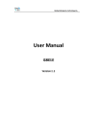
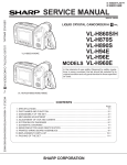
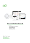
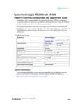
Wisnetworks System Configuration Manual This document contains information that is proprietary to Wisnetworks Technologies. No part of this publication may be reproduced, modified, or distributed without prior written authorization of Wisnetworks Technologies Co,. Ltd. This document is provided as is, without warranty of any kind. Statement of Conditions The information contained in this document is subject to change without notice. Wisnetworks shall not be liable for errors contained herein or for incidental or consequential damage in connection with the furnishing, performance, or use of this document or equipment supplied with it. Information to User Any changes or modifications of equipment not expressly approved by the manufacturer could void the user's authority to operate the equipment and the warranty for such equipment. Copyright © 2012-2014 WISNETWORKS Technologies Co., Ltd. All rights reserved. Page 2 , Total 42 Wisnetworks System Configuration Manual 1. Hardware Connection ....................................................................................................................... 5 1.1 Connect with PoE Adapter ................................................................................................... 5 1.2 Local Network Settings ................................................................................................................ 6 2. Software Configuration ..................................................................................................................... 8 2.1 Main Page ............................................................................................................................... 8 2.1.1 Status-WIRELESS ........................................................................................................... 8 2.2 2.3 2.4 2.5 2.1.2 Status-NETWORK ..................................................................................................... 10 2.1.3 Status-SYSTEM......................................................................................................... 12 2.1.4 Monitor-Throughput ................................................................................................... 12 2.1.5 Monitor-Interfaces ...................................................................................................... 12 2.1.6 Monitor-ARP List........................................................................................................ 13 2.1.7 Monitor-STA Stats ..................................................................................................... 13 2.1.8 Monitor-AP Stats........................................................................................................ 15 2.1.9 Monitor-Routes .......................................................................................................... 15 2.1.10 Monitor-PPPoE Information List................................................................................ 16 2.1.11 Monitor-DHCP Server ................................................................................................ 17 Radio Page ........................................................................................................................... 17 2.2.1 Basic Wireless Settings ............................................................................................. 17 2.2.2 Advanced Wireless Settings ...................................................................................... 21 2.2.3 WMM Settings ........................................................................................................... 22 WIRELESS Page .................................................................................................................. 22 2.3.1 AP/AP WDS Mode ..................................................................................................... 22 2.3.2 Station/Station WDS Mode ........................................................................................ 24 NETWORK ......................................................................................................................... 25 2.4.1 Bridge Mode ............................................................................................................... 25 2.4.2 WISP/SOHO Router Mode ......................................................................................... 28 SERVICES ......................................................................................................................... 30 Page 3 , Total 42 Wisnetworks System Configuration Manual 2.6 2.7 2.5.1 Web Server ................................................................................................................ 30 2.5.2 Telnet Server ............................................................................................................. 31 2.5.3 Security Basic ............................................................................................................ 32 2.5.4 Security Service ......................................................................................................... 32 2.5.5 Virus Protection ......................................................................................................... 33 2.5.6 Website Control ......................................................................................................... 33 2.5.7 MAC Control .............................................................................................................. 34 SYSTEM ............................................................................................................................ 34 2.6.1 Device ........................................................................................................................ 35 2.6.2 Ping Watchdog .......................................................................................................... 35 2.6.3 System Accounts ....................................................................................................... 36 2.6.4 Configuration Management........................................................................................ 36 2.6.5 Firmware upgrade...................................................................................................... 37 Tools .................................................................................................................................. 38 2.7.1 Ping ........................................................................................................................... 38 2.7.2 Traceroute ................................................................................................................. 39 2.7.3 Site survey ................................................................................................................. 39 2.7.4 Speed Test ................................................................................................................ 40 Declaration of Conformity........................................................................................................................ 42 Page 4 , Total 42 Wisnetworks System Configuration Manual 1. Hardware Connection All Wisnetworks products are powered by PoE (Power over Ethernet). The connecting diagram showed below (here using a CPE WIS-Q2300 as example) The connection step is Connect the device with an Ethernet cable. Connect the other end of the cable into POE port of power adapter. Page 5 , Total 42 Wisnetworks System Configuration Manual Using another Ethernet cable, connect one end of cable into LAN port of adapter, the other end into computer port. Plug the power adapter into an outlet to power up the device. If you are using our 5GHz radios, most of them are using Gigabit LAN port. Thus you should connect them with a CAT-5E or CAT-6 cable to get the maximum performance. Set PC and set IP address as 192.168.1.x(x is 1-254 except 2,to make sure no conflict with other IP in the network.) Run Web browser, input http://192.168.1.2(default IP address)and enter. Figure 2, default username:admin, password:admin (You can change this password after entering the system) , and then click Login to the software system. Page 6 , Total 42 Wisnetworks System Configuration Manual Page 7 , Total 42 Wisnetworks System Configuration Manual 2. Software Configuration Figure 2-1 Wireless Status(Access Point Mode) Figure 2-2 Wireless Status(Station Mode) 2.1.1 Status-WIRELESS Radio status window, mainly shows the radio work mode and related information of the unit. Wireless mode:working mode of the unit, supporting 4 kinds of working mode, AP Mode、 Station Mode、AP WDS Mode and Station WDS Mode. Radio mode: working mode of Radio, supporting 802.11a/an two kinds of working modes. Page 8 , Total 42 Wisnetworks System Configuration Manual Channel/Frequency: radio current working channel and working frequency. Channel Width: radio channel bandwidth , supporting 20MHz and 40MHz. Channel bandwidth has great influence to the wireless. Under no interference environment, average throughput of 40MHz channel bandwidth can reach more than twice of 20MHz channel bandwidth. Country Code: country code of current working Radio. Different country code has different channel and power for Radio supporting. Tx Power: current Radio transmission power. Transmission power influences directly signal strength of communication system, so we should guarantee transmission power big enough; Max Rate: max sending rate of Radio supporting. Different channel bandwidth could affect max sending rate. If AP and Station can reach to 40MHz channel bandwidth, max sending rate can reach to 300Mbps, and throughout rate can improve more than twice. WiD TDMA: the status of WiD TDMA with „enable‟ or „disable‟. Station status box shows the unit working as Station Mode. Figure 2-3 Wireless Station Status Up/Down: UP means CPE has successfully connected with AP. Down means the link is not built. SSID: SSID name of AP that CPE is connecting. BSSID: BSSID address of AP that CPE is connecting. Signal Strength: signal strength of AP that CPE is connecting. Signal strength is negative, the smaller the absolute value of signal strength, the stronger it proves between CPE and AP. When it transmits in long distance, stronger signal can ensure higher thorough for wireless transmission. Security: security way of AP that CPE is connecting, CPE supporting None/WEP/WPATKIP/WPA-CCMP/WPA2-TKIP/WPA2-CCMP/WPA mix encryption and WPA2 mix encryption Page 9 , Total 42 Wisnetworks System Configuration Manual connecting AP. Wireless1/2/3/4 status box shows the unit working as AP Mode. Our radio supports at most 4 wireless services, representing Wireless1/2/3/4. Figure 2-4 Wireless Access Point Status Up/Down: UP means interface of wireless service has started to work, and is providing wireless access services. And down means it has not SSID: SSID of wireless service. BSSID: BSSID of wireless service broadcast Beacon using. Security: security way of wireless service using, supporting None/WEP/WPA-TKIP/WPACCMP/WPA2-TKIP/WPA2-CCMP/WPA mix encryption and WPA2 mix encryption. 2.1.2 Assoc Number: current online clients connected to this unit. Status-NETWORK Network Role Network Mode: device supports 3 kinds of Network Modes, including Bridge Mode, SOHO Router Mode and WISP Mode. Page 10 , Total 42 Wisnetworks System Configuration Manual A brief introduction to those modes: 1. Bridge Mode: bridge Mode is typical 2-layer network mode. The unit ETH port and wireless interface are working at layer-2 network mode, no independent IP address. For the whole unit only has one Bridge port IP address. 2. SOHO Router Mode: this mode is typical network mode of wireless router. The ETH port is worked as WAN interface, connecting another network by ETH port, such as Internet or enterprise network. This device connects with public network supporting three ways: static IP address, DHCP dynamic IP address and PPPoE. Only when the unit works as AP Mode and AP WDS Mode, network mode can be set as SOHO Router Mode. 3. WISP Mode: this mode is opposite to SOHO Router. It uses wireless interface as WAN to connect public network and ETH port as 2-layer access port. For this mode we can think the unit as a wireless client router supporting PPPoE over air. Only when the unit works as Station Mode or Station WDS Mode,network mode can be set as WISP Mode. Network Settings Bridge IP Address: IP address of Bridge interface. Net mask: net mask of bridge interface IP address. Bridge Mac: MAC address of bridge interface. Gateway: gateway IP Address of bridge interface. Primary DNS IP: primary DNS address of bridge interface. Secondary DNS IP: secondary DNS address of bridge interface. Page 11 , Total 42 Wisnetworks System Configuration Manual 2.1.3 Status-SYSTEM Figure 2-6 System lable of status Device Name: device name or model name Serial Number: device serial NO. Software Version: current software version Language: current web language Time zone: current time zone Current time: current time Username: username when login 2.1.4 Monitor-Throughput Figure 2-7 Monitor-Throughput 2.1.5 Monitor-Interfaces Interfaces list counts send-receive info of all interfaces. Page 12 , Total 42 Wisnetworks System Configuration Manual Figure 2-8 Monitor-Interfaces Interface:listing all interfaces and interface name. MAC Address:listing MAC address of all interfaces. Tx Bytes:sending bytes number. Tx Packet:sending packet . Tx Err:sending error packet . Rx Bytes:receiving bytes . Rx Packet: receiving packet. Rx Err: receiving error packet. 2.1.6 Monitor-ARP List ARP List counts ARP information of device learning, as Figure 2-9. Figure 2-9 Monitor-ARP List IP: IP address of device learning. MAC: MAC address corresponding to IP address of device learning. Interface: interface to IP address of device learning. Type: interface hardware type of learning ARP. 2.1.7 Monitor-STA Stats When the unit works as AP Mode, a list shows STA info of current clients as Figure 2-10 Page 13 , Total 42 Wisnetworks System Configuration Manual Figure 2-10 Monitor-STA Stats Figure 2-11 Station Details BSSID:BSSID of STA connecting wireless services. Mode:working mode of STA Radio. AID: connecting ID of STA. Signal:AP detected RSSI of STA. Assoc Time:time online of STA. Tx/Rx Packets:send-receive packets between AP and STA. Tx means sending packets from AP to STA, Rx means receiving packets from STA to AP. Page 14 , Total 42 Wisnetworks System Configuration Manual Tx/Rx Bytes: send-receive bytes between AP and STA. Tx means sending bytes from AP to STA, Rx means receiving bytes from STA to AP. Tx/Rx Rate: rate using by send-receive packets between AP and STA. Tx means senidng rate from AP to STA, Rx means receving rate from STA to AP, in fact it is sending rate of STA. 2.1.8 Monitor-AP Stats When the unit works as Station Mode, the list shows info of CPE connecting AP, as Figure 2-12 Figure 2-12 Monitor-AP Stats SSID: SSID name of AP that CPE is connecting. BSSID: BSSID address of AP that CPE is connecting. Mode:radio work mode of AP that CPE is connecting. Channel: work channel of AP that CPE is connecting. Signal: CPE detected AP RSSI. Assoc Time:duration online after CPE is connecting AP. Tx/Rx Packets:send-receive packets between CPE and AP. Tx means sending packets from CPE to AP, Rx means receiving packets from AP to CPE. Tx/Rx Bytes: send-receive bytes between CPE and AP. Tx means sending bytes from CPE to AP, Rx means receiving bytes from AP to CPE . Tx/Rx Rate: rate using by send-receive packets between CPE and AP. Tx means senidng rate from CPE to AP, Rx means receving rate from AP to CPE, in fact it is sending rate of AP. 2.1.9 Monitor-Routes Routes list shows current routing relationship of device, as Figure 2-13. Page 15 , Total 42 Wisnetworks System Configuration Manual Figure 2-13 Monitor-Routes Destination: destination address and mask; Gateway:next address against destination address, that is gateway address. Flags:network type of this routing info. Interface:interface of this routing info. 2.1.10 Monitor-PPPoE Information List PPPoE information list shows connecting state of current PPoE, as Figure2-14. Figure 2-14 Monitor-PPPOE Server Name:server name of PPPoE server. Connection Time:time online of PPPoE connection. Local IP Address:local IP address of PPPoE client. Remote IP Address:remote IP address of PPPoE server. Primary DNS IP:primary DNS address of PPPoE client. Secondary DNS IP:secondary DNS address of PPPoE client. TX Packets:CPE sending packets by PPP interface. RX Packets:CPE receiving packets by PPP interface. TX Bytes: CPE sending bytes by PPP interface. RX Bytes: CPE receiving bytes by PPP interface. Page 16 , Total 42 Wisnetworks System Configuration Manual 2.1.11 Monitor-DHCP Server DHCP Server List shows status of assigning IP address when CPE is DHCP Server, as Figure 2-15. Figure 2-15 Monitor-DHCP Server MAC Address:MAC address of DHCP Client. IP Address:IP address of DHCP Client. Remaining Lease: remaining lease to this IP address of DHCP Server. Hostname:hostname of DHCP Client. Radio Page is mainly used for setting WLAN RF parameter, as Figure 2-16. Figure 2-16 Radio Page 2.2.1 Basic Wireless Settings Figure 2-17 Wireless Mode Wireless Mode:working mode of WLAN, the unit supporting AP Mode, Station Mode, AP WDS Mode and Station WDS Mode, the default is Station Mode. Because settings of those 4 Page 17 , Total 42 Wisnetworks System Configuration Manual modes have little impact to parameter setting of whole Radio,we will not introduce parameter setting of Radio for 4 modes. Figure 2-18 Country Code Country code:set country code of Radio, the default is Unite States. Figure 2-19 IEEE 802.11 Mode IEEE 802.11 Mode: set working mode of Radio, the default is 802.11n. Figure 2-20 Channel Width Channel Width:set occupied bandwidth of channel, the default is 20/40MHz Mode. Page 18 , Total 42 Wisnetworks System Configuration Manual Figure 2-21 Channel Channel: set working channel of Radio, the default is auto channel. 、 Figure 2-22 Tx Power Page 19 , Total 42 Wisnetworks System Configuration Manual Tx Power:set transmission power of Radio, the default is 24dBm. Tx power has different limit for each country. When changing the tx power the user or operator should follow the regulatory rules. Transmission power can influence signal strength of wirelss communication. when it transmits in long distance, please properly increase transmit power to ensure stronger singal. And when testing indoor, pls properly decrease transimission power in order to prevent signal saturation for higher signal strength. Figure 2-23 Max TX Rate Max TX Rate:set packets sending rate of Radio. 2.4GHz/5GHz radio is 2X2 device, so max support is MCS=15 and default setting. Page 20 , Total 42 Wisnetworks System Configuration Manual 2.2.2 Advanced Wireless Settings Figure 2-24 RTS Threshold RTS Threshold:set RTS/CTS threshold, the default is off state. RTS/CTS is mainly to prevent hidden node disturbing. But if RTS/CTS threshold is setting too much smaller, it may obviously reduce throughtput rate of wireless communication. Fragmentation Threshold:set fragmentation threshold, the default is off state. Distance: set transmission distance between AP and STA, so that system can choose proper ACK _timeout, the default is 3Km. When it is transmitting in long distance, proper adjusting distance can improve throughtput. Aggr Enable:set “enable” and “to enable”sending function of A-MPDU, the default is enable state. Aggr limit Enable: set sending limit function of A-MPDU, the default is enable state, the max aggr packet of the default is 64 units, the max aggr length is 60000 bytes. As long as one conditon meets, it will trigger aggr limit. Page 21 , Total 42 Wisnetworks System Configuration Manual 2.2.3 WMM Settings Figure 2-25 WMM Settings Wireless Page is used for setting wireless service of AP Mode or relevant parameters for Station Mode connecting AP . 2.3.1 AP/AP WDS Mode When the unit is set as AP/AP WDS Mode, Wireless Page is shown as Figure 3-12. 1. Wireless Settings Wireless1/2/3/4:device can be set with 4 wireless service at most, separately 4 labels to distinguish. Wireless Availability:working “Enable” or “Disable” wireless service, the default is “Enable” status for Wireless1, and „Disabled‟ for others. Hide SSID:working “Enable” and “Disable” hiding SSID function. The function would make the base station hidden from searching by other clients. The default is “Disable” status. SSID: text box for entering the name of the wireless service. Page 22 , Total 42 Wisnetworks System Configuration Manual Figure 2-26 Wireless Page 2. Wireless Security Security:set security type, the default is „None‟.If choosing WEP security type, as shown Figure 2-27. Figure 2-27 WEP Security Type Authentication Type:set authentication method, the default is open. WEP Key Length:set WEP key length, the default is 64 bit. Key Type:set key type , the default is ASCII type. WEP Key:enter WEP key. Key Index:choose key index, the default is 1. If choosing WPA/WPA2 security type, as shown Figure 2-28. Figure 2-28 WPA security type Page 23 , Total 42 Wisnetworks System Configuration Manual Figure 2-29 WPA2 security type WPA Authentication: set WPA/WPA2 authentication method, current only supporting PSK . WPA Preshard Key:set PSK key of WPA/WPA2, supporting ASCII and Hex. 2.3.2 Station/Station WDS Mode When the unit is set as Station/Station WDS Mode, Wireless Page is shown as Figure 2-30. Figure 2-30 Wireless Setting Page 1. Wireless Settings SSID: when the unit is set as Station Mode, enter here SSID of linked AP. If just enter SSID not AP MAC address, it will choose the strongest signal among the same SSID to connect to. Lock to AP MAC: lock MAC address needing to link AP. After SSID and AP MAC both enter, it will connect to the AP which meet two condition, not only same SSID. Scan: scan button is used for scanning SSID with available channels, as Figure 2-31. Figure 2-31 Scan List Page 24 , Total 42 Wisnetworks System Configuration Manual MAC Address: BSSID address of wireless service. SSID: BSSID name of wireless service, also called ESSID. Auth_mode: authentication method of the wireless service. Encryption: encryption types of the wireless service . Signal/Noise: signal strength and noise floor of wireless service. Frequency:working frequency of the wireless service. Channel: working channel of the wireless service. Lock to AP: if click this button, the unit would lock the BSSID of this wireless service. 2. Wireless Security The unit would automatically choose the right encryption type, and you need to input the encryption key in this textbox. NETWORK Page is used for setting relevant parameters of network mode. The unit supports Bridge Mode, SOHO Router Mode and WISP Mode. SOHO Router Mode and WISP Mode is the same for settings page, here is introduction about Bridge Mode and WISP Mode. 2.4.1 Bridge Mode Setting of Bridge Mode is shown as Figure 2-32. Page 25 , Total 42 Wisnetworks System Configuration Manual Figure 2-32 Bridge Mode 1. Network Role Network Mode: set current network mode. Figure 2-33 Edit VLAN Page 26 , Total 42 Wisnetworks System Configuration Manual Figure 2-34 Edit VLAN Interface 2. Management Network Settings Bridge IP Address: bridge IP address obtaining way, separately static set and DHCP access. IP Address: set static IP address. Netmask: set netmask of static IP address. Gateway IP:set static gateway address. Primary DNS IP: set static main DNS address. Secondary DNS IP: set static backup DNS address. MTU: set MTU, the default is 1500 bytes. 3. LAN Network Settings DHCP Server: working “enable” or “to enable” DHCP Server function, the default is “to enable”state. Range Start:set range start IP address of DHCP Server address pool. Range End:set range end IP address of DHCP Server address pool. Netmask:set netmask of DHCP Server address field. Lease Time: set lease time DHCP Server assigned address. DNS Proxy: working “enable” or “to enable” DNS proxy function. Page 27 , Total 42 Wisnetworks System Configuration Manual 2.4.2 WISP/SOHO Router Mode Setting of WISP/SOHO Router Mode is shown as Figure 2-35. Figure 2-35 Setting Page 1. Network Role Network Mode : set current network mode. 2. WAN Network Settings WAN IP Address: WAN IP adsress obtaining way, separately static set, DHCP access and PPPoE negoiation. Because static set and DHCP access are the same with setting of Bridge Mode, there is directly introduction PPPoE. Username: set PPPoE connection username . Password: set PPPoE connection password. Service Name: set PPPoE connection service name. Fallback IP: set fallback IP address after PPPoE negoiation failed. Fallback Netmask: set fallback netmask of IP address after PPPoE negoiation failed. MTU/MRU: set MTU and MRU PPPoE negoiation. Encryption: set MPPE Agreement when“enable” or “to enable” PPPoE negoiation is using (Microsoft Point-to-Point Encryption Agreement). NAT:set NAT service of “enable” or “disabled” with the checkbox. NAT Protocol:for some NAT service of special agreement, it needs to enable alone, CPE supporting NAT service of SIP、RSTP、FTP and PPTP. Page 28 , Total 42 Wisnetworks System Configuration Manual 3. LAN Network Settings Figure 2-36 Setting Page IP address: set IP address of management devices. Netmask: set netmask of IP address. DHCP Server: work “enable” or “to enable” DHCP Server function, the default is “to enable”state. Range Start: set range start IP address of DHCP Server address pool. Range End: set range end IP address of DHCP Server address pool. Netmask:set netmask of DHCP Server address field. Lease Time: set lease time DHCP Server assigned address. DNS Proxy: working “enable” or “to enable” DNS proxy function. Figure 2-37 Static Routes Figure 2-38 Port Forwarding Page 29 , Total 42 Wisnetworks System Configuration Manual Figure 2-39 Traffic Shaping Services Page is used for setting safe access, access management and so on, as Figure 2-40. Figure 2-40 Services 2.5.1 Web Server Figure 2-41 Web Server Server Port: set server port of web service, the default is 80. Page 30 , Total 42 Wisnetworks System Configuration Manual Session Timeout: set web session timeout, the default is 15 minutes. 2.5.2 Telnet Server Figure 2-42 Telent Server Enable Telnet Server: working “enable” or “to enable” Telnet server, the default is “to enable”state. Server Port: set server port of telnet server, the default is 23. Figure 2-43 NTP Client Figure 2-44 System Log Figure 2-45 Client Rate Limit-All Clients Figure 2-46 Client Rate Limit-Classified Clients Page 31 , Total 42 Wisnetworks System Configuration Manual 2.5.3 Security Basic Figure 2-47 Security Basic Security Basic is used for defending common outer net attack, including intrusion 、damage,and obtaining or changing sensitive data. Page is set as Figure 2-47. port scan detect: port scan, if enable, refuse outer net to scan equipment. ping of death detect: ping flood attack, if enable, still allow ping request, but restrict frequent ping request. sync flood attack detect: sync flood attack, if enable, restrict frequency of sending sync. fragment attack detect: fragment attack, if enable, restrict fragment package of outer net. spoofing attack detect: spoofing attack, if enable, prevent outer net linking by using inner net IP. ping attack detect: ping request, if enable, abandon ping requestof outer net sending. tcp null scan detect:tcp null scan, if enable, abandon null scan of tcp sending. ACK cheat detect:ack request, if enable, abandon false ack package of tcp sending. finger scan detect:finger scan, if enable, abandon relevant requests of finger service. netbios scan detect:netbios scab, if enable, abandon relevant requests of netbios service. 2.5.4 Security Service Security Service is mainly used for forbidding or allowing access of some web service, as Figure 2-48. Figure 2-48 Security Service ftp:port 21, if enable, forbid ftp service. Page 32 , Total 42 Wisnetworks System Configuration Manual ssh:Port 22, if enable, forbid ssh service. telnet:port 23, if enable, forbid telnet service. http:port 80, if enable, forbid http service. dns:port 53, if enable, forbid dns service. If enable corresponding service by http, it will forbid http service, and user cannot visit through browser. 2.5.5 Virus Protection Figure 2-49 Virus Protection Virus protection can prevent common network virus attack, as shown Figure 2-46. worm_virus: worm virus, if enable, prevent worm virus attack. shake_virus: shake virus, if enable, prevent shake virus attack. shock_virus: shock virus, if enable, prevent shock virus attack. hackers_horse:hackers horse, if enable, prevent hackers horse attack . netbus_horse: netbus horse, if enable, prevent netbus horse attack. netspere_horse: netspere horse, if enable, prevent netspere horse attack. 2.5.6 Website Control Website Control can set web blacklist. If web address is in the list, user cannot visit them. Now 20 website can be set, if do not control website, all website can be visit, as shown Figure 2-50. Figure 2-50 Website Control Page 33 , Total 42 Wisnetworks System Configuration Manual 2.5.7 MAC Control MAC Control means to restrict Internet access by computer MAC address, and manage access and visit of users by supporting blacklist or white list. Don‟t open MAC control in the case of the default, that is to say, all computers can visit Internet without limit, as Figure 2-51. Figure 2-51 MAC Control MAC Control is available to all ports. Pls be careful to setup. System Page is mainly used for setting relevant device management, as Figure 2-49. Figure 2-52 System Page Page 34 , Total 42 Wisnetworks System Configuration Manual 2.6.1 Device Figure 2-53 Device Device Description: set device description. Enable Startup Date: set enable startup date, the default is enable state. Startup Date:set device startup date. 2.6.2 Ping Watchdog Figure 2-54 Ping Watchdog Time zone: set device time zone. Page 35 , Total 42 Wisnetworks System Configuration Manual 2.6.3 System Accounts Figure 2-55 System Accounts Username: set admin username. Current Password: amending username and new password after entering current password. New Password: set new password. Verify New Password: verify new password. 2.6.4 Configuration Management Figure 2-56 Location Page Figure 2-57 Configuration Management Figure 2-58 Restore Factory-default settings Page 36 , Total 42 Wisnetworks System Configuration Manual Figure 2-59 Import the configuration file Figure 2-60 Device Reboot Restore Factory defaults:restore factory default. Export Configuration :export latest configuration. Import Configuration:import configuration into device. Reboot:reboot device. 2.6.5 Firmware upgrade Figure 2-61 Firmware Upgrade Firmware upgrade is used for upgrading software of the device. Page 37 , Total 42 Wisnetworks System Configuration Manual 2.7.1 Ping The ping test is usually used for measuring the network latency performance. Figure 2-62 Network Ping Destination IP :the target IP address Packet Count: number of the ping times Packet Size: define the ping/ICMP packet size, the larger size of the packet the higher latency for the ping Page 38 , Total 42 Wisnetworks System Configuration Manual 2.7.2Traceroute Figure 2-63 Network Traceroute Destination host :the target IP address/domain for tracing Resolve IP Address: allow to enter IP address 2.7.3 Site survey Figure 2-64 Scan List MAC Address: BSSID address of wireless service. SSID: BSSID name of wireless service, also called ESSID. Auth_mode: authentication method of the wireless service. Encryption: encryption types of the wireless service . Signal/Noise: signal strength and noise floor of wireless service. Frequency:working frequency of the wireless service. Channel: working channel of the wireless service. Page 39 , Total 42 Wisnetworks System Configuration Manual 2.7.4 Speed Test Figure 2-65 Network Speed Test Destination IP :the target IP address, in most condition is the IP of the opposite radio Web Port: default is 80 Username: default is admin Password: default is admin Type: transmit/receive/duplex speed performance of wireless Test Result: after pressing the apply button for a few seconds, the test result would come out If you require specific throughput, you should use a test tool like iperf or chariot. The speed test tool can only provide a rough result. Page 40 , Total 42 Wisnetworks System Configuration Manual Appendix A Acronym Explanation 802.11 A family of specifications related to wireless networking, including: 802.11a, 802.11b, and 802.11g. Access Point. The hub of a wireless network. Wireless clients connect to the access point, and traffic between two clients must travel through the access point. Access points are often abbreviated to AP Broadcast Service Set Identifier Customer Premises Equipment Dynamic Host Configuration Protocol. A protocol which enables a server to automatically assign an IP address to clients so that the clients do not have to configure the IP addresses manually. Extensible Authentication Protocol. A standard form of generic messaging used in 802.1X. EGOed Service Set Identifier Client mode compared to Access Point Service Set Identifier, a set of characters that give a unique name to a WLAN. Temporal Key Integrity Protocol Virtual Local Access Network Wireless Distribution System Wired Equivalent Privacy. An encryption system created to prevent eavesdropping on wireless network traffic. Wireless Individual Division technology Time division multiple access Wi-Fi Protected Access. A modern encryption system created to prevent eavesdropping on wireless network traffic. It is considered more secure than WEP. WPA-Extensible Authentication Protocol WPA-Pre-Shared Key AP BSSID CPE DHCP EAP ESSID Station SSID TKIP VLAN WDS WEP WiD TDMA WPA WPA-EAP WPA-PSK Page 41 , Total 42 Wisnetworks System Configuration Manual Declaration of Conformity Hereby, WISNETWORKS Technologies Co., Ltd. , declares that this Wisnetworks device, is in compliance with the essential requirements and other relevant provisions of Directive 1999/5/EC. Wisnetworks Technologies CO., LTD. No.77, FuTe West 3 Road, China (Shanghai) Pilot Free Trade Zone CE Mark Warning This is a class B product. In a domestic environment, this product may cause radio interference, in which case the user may be required to take adequate measures. Page 42 , Total 42