1
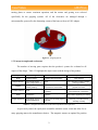
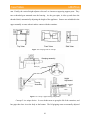
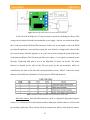
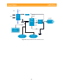
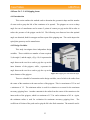
Figure 4.4. H-bridge connection to the motor and microcontroller
To the left of the H-bridge, the 5 Volts necessary to operate the H-Bridge are shown. This
voltage can be obtained from the microcontroller power supply. Also the two connections below
the 5 Volts represent the PWM and Direction pins. In this case, an On signal is sent to the PWM
pin when the appliance is activated (by pressing the ‘start’ button). A change in the value for this
pin is not necessary when the appliance is on, as we do not need to change the speed of the motor
or the pulse modulation. The Direction pin will receive either a 1 or 0 signal to control the motor
direction. Connecting both pins to two of the Mini-Max I/O ports can do this. The motor
behavior is dictated by the value of the I/O ports given by the microcontroller, which are
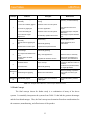
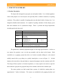
controlled by the status of the hall effect and push-button sensors. Table 4.1 shows the motor
behavior for the different combination of values given to PWM and Direction
Table 4.1. Function Table that characterizes the behavior of the motor.
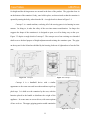
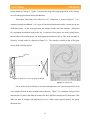
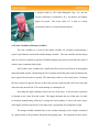
Hall effect sensors: Four hall effect sensors are used, as explained in the product logistics
section. Two of them will be in the bottom assembly radial plate, and the other two will be in the
top assembly spiral plate. These sensors tell the microprocessor when to turn off/on the motors,
21