1
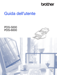
SS10C-C65H
SS10W-C65H
Indoor Ceiling Mount
Outdoor Wall Mount
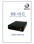
10x Mini PTZ Camera
Indoor
Outdoor
USER MANUAL
FEATURES
1/4" Interline Transfer CCD, 650 TV Lines
10x Optical Zoom, 10x Digital Zoom (Max 100x Zoom)
F1.8, f=3.8~38mm focal length
0.7 lux (color) / 0.02 lux (B&W), 50 IRE
Mechanical IR Cut Filter (ICR), Day & Night Function
360° Endless Pan ; 180° Auto-flip Tilt ; 95° Normal Tilt
127 Presets ; RS-485 Communication, max 255 cameras
Pelco-D & Pelco-P Selectable protocols
Vector Drive Technology: Pan/Tilt motions are done at the shortest path
4 Alarm Inputs – SS10W-C65H
Fan & Heater – SS10W-C65H
12V DC
Copyright © 2012 by OKINA USA. All Rights Reserved.
** Replacing SS10C-C480DN
P-044_P-045
R201204-V27
Please read the Manual before attempting to use this product.
Specifications and appearance are subject to change without notice.
Disposal of Old Electrical & Electronic Equipment (Applicable in the
European Union and other European countries with separate collection
systems).
This symbol on the product or on its packaging indicates that this product shall not be
treated as household waste. Instead it shall be handed over to the applicable collection
point for the recycling of electrical and electronic equipment. By ensuring this product is
disposed of correctly, you will help prevent potential negative consequences for the
environment and human health, which could otherwise be caused by inappropriate
waste handling of this product. The recycling of materials will help to conserve natural
resources. For more detailed information about recycling of this product, please contact
your local city office, your household waste disposal service or the shop where you
purchased the product.
CAUTION
1. Never point the camera toward the sun
Do not expose the lens directly to the sun or to strong light as this may damage the
pick-up device.
2. Handle this camera with care
Avoid any shock or bumping of the camera. Improper handling could damage the
camera.
3. Requires a proper operating environment
The ceiling mount camera is designed for indoor use. The allowable temperature
range for operation is between 32°F ~ 104°F / 0C ~ 40C. The wall mount camera is
designed for outdoor use. The allowable temperature range for operation is between
-22F ~ 122F / -30C ~ 50C.
2
4. Clean the front face or lens
It is recommended that the surface be cleaned every 3~6 months. Cleaning should be
done by using a chamois, a very fine soft cloth, lens tissue, or cotton tipped applicator
and ethanol to carefully remove any fingerprint or dust.
5. Check the power source voltage
The power source voltage should be within the specified range. (Camera must meet
the specifications). Camera must be connected to a surge protector at all times.
6. Objects and liquid entry
Never push objects of any kind into this camera as this may touch dangerous voltage
points of short out parts that could result in a fire or electric shock. Never spill any kind
of liquid on the video product.
7. Servicing
Do not attempt to service this video product by yourself as opening or removing
covers may expose you to dangerous voltage or other hazards. Refer all service to
qualified servicing personnel.
8. Damage requiring service
Unplug this video product from the wall outlet and refer service to qualified servicing
personnel under the following conditions:
a. When the power supply cord or plug is damaged.
b. If liquid has been spilled, or objects have fallen into the video product.
c. If the video product has been exposed to rain or water.
d. If the video product has been dropped or the cabinet has been damaged.
e. When the video product exhibits a distinct change in performance.
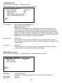
LIMITED WARRANTY
OKINA USA products are covered under warranty for one year from the date of
purchase. The warranty will automatically be voided if any of the following occurs:
1. Camera sticker is removed
If the camera sticker is removed, we will not be able to confirm any information
regarding when and where the product was purchased. We have no other way to
verify the purchase record without the serial number on the camera sticker; therefore,
it should not be removed.
2. Camera is modified in any way
If the camera is scratched, damaged, or modified in a manner not described in this
manual, the warranty will be voided immediately. It is the customer’s responsibility to
keep the camera in good condition.
3. Video or power cable is cut
The video cable and the power cable should not be tampered with. Cutting or
modifying of the cables will result in termination of the warranty.
3
INDEX
FEATUERS ……………………………………………………………………………………. 1
CAUTIONS ………………………………………………………………………………….. 2-3
LIMITED WARRANTY ……………………………………………………………………….. 3
PACKAGE CONTENTS ……………………………………………………………………… 5
DIMENSIONS ……………………………………………………………………..………... 5-6
DIP SWITCH SETTING ……………………………………………………………………. 7-8
APPLICATION DIAGRAM ………………………………………………………..…………. 8
INSTALLATION …………………………………………………………………………… 9-10
OPERATION ……………………………………………………………………………….10-14
PRESET AND PATTERN FUNCTION PRE-CHECK …………………….……. 10
STARTING OSD MENU …………………………………………………….……. 11
RESERVED PRESET …………………………………………………………….. 11
PRESET …………………………………………………………………………..... 11
SWING ……………………………………………………………………………… 12
PATTERN ……………………………………………………………………... 12-13
GROUP …………………………………………………………………………….. 13
OTHER FUNCTIONS ………………………………………………………………14
HOW TO USE OSD MENU ………………………………………………………….…. 15-31
OSD DISPLAY OF MAIN SCREEN …………………………………………...... 15
GENERAL RULES OF KEY OPERATION FOR MENU ………………………. 16
MAIN MENU ……………………………………………………………………….. 16
DISPLAY SETUP …………………………………………………………..…. 16-17
PRIVACY ZONE MASK SETUP ………………………………………..…… 17-18
CAMERA SETUP ……………………………………………………….…….. 19-20
MOTION SETUP ………………………………………………………….….. 21-23
PRESET SETUP ……………………………………………………………... 23-25
SWING SETUP ………………………………………………………………. 25-26
PATTERN SETUP …………………………………………………….……… 26-27
GROUP SETUP ………………………………………………….…………… 27-29
SYSTEM INITIALIZE ……………………………………………..………….. 30-31
SPECIFICATION ……………………………………………………………..…………….. 32
4
PACKAGE CONTENTS
One (1) 10x Mini PTZ Dome Camera
One (1) Mounting Base
Three (3) Mounting Base Screws
Three (3) Thread Connector Screws
One (1) Thread Connector
One (1) User Manual
*Ceiling bracket is standard for mini PTZ Dome.
* Arm Type Wall mount bracket is standard for Outdoor PTZ Dome.
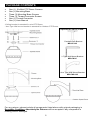
Options for SS10C-C65H:
Pendant Pole Bracket
MB-CP10C
L Type Wall Mount Bracket
MB-CW1C
Arm Type Wall Mount Bracket
MB-CWA10C
For any returns, please include all components listed above with original packaging in
Resalable Condition. Absolutely No Returns will be accepted if any component is
missing and/or damaged.
5
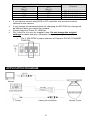
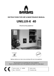
DIMENSIONS
Indoor Ceiling Mount
7.36” / 187mm
Ø 5.04” / 128mm
Ø 4.2” / 107.7mm
Ø 5” / 127mm
Outdoor Arm Type Wall Mount
With Pendant Pole Mount
With L Type Wall Mount
6
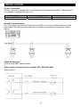
DIP SWITCH SETTING
Before you install the camera, you should set the DIP switches to configure the
camera ID, communication protocol.
Camera ID Setup
ID number of camera is set using binary number. The example is shown
below.
Pin
ID Value
Ex) ID=5
Ex) ID=10
1
1
Off
Off
2
2
Off
Off
3
4
Off
Off
4
8
Off
Off
5
16
Off
Off
6
32
Off
Off
7
64
Off
Off
8
128
Off
Off
The range of ID is 1~255. Do not use 0 as Camera ID. Factory default is 1.
If you want to control a certain camera, you must match the camera ID with
the Cam ID setting of DVR or Controller
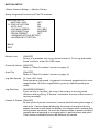
Communication Protocol Setup
Select the appropriate Protocol with DIP switch combination.
7
Switch State
P0
(Pin 1)
OFF
ON
OFF
ON
P1
(Pin 2)
OFF
OFF
ON
ON
Protocol
PELCO-D, 2400 bps
PELCO-D, 9600 bps
PELCO-P, 4800 bps
PELCO-P, 9600 bps
If you want to control using DVR or P/T controller, the protocol must be
identical to the camera.
If you change the camera protocol by changing the DIP S/W, the change will
be effective after you reboot the camera.
Factory default is Pelco-D, 2400 bps
Pin 3 and Pin 4 is only for supplier’s use. Do not change the original
settings for these two pins, otherwise, the camera may not operate
normally.
o Pin 3: PAL/NTSC system selection of Camera. DO NOT CHANGE
THIS PIN.
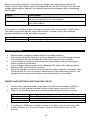
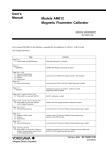
APPLICATION DIAGRAM
Monitor
Cabling Terminal Block
8
INSTALLATION
Power Connection
Please, check the voltage and current capacity of rated power carefully. Rated power
is indicated in the back of main unit.
Rated Power
12V DC
Input Voltage Range
11V~18V DC
Current Consumption
0.8 A
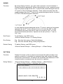
RS-485 Communication
For PTZ control, connect the keyboard and DVR. To control multiple cameras at the
same time, RS-485 communication lines of them is connected in parallel as shown
below.
Video Connection
Connect with BNC coaxial cable.
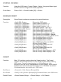
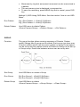
Alarm input Connection (For Outdoor PTZ, SS10W-C65H)
Sensor Input
9
Before connecting sensors, check driving voltage and output signal type of the
sensor. Since output signal types of the sensors are divided into open collector and
voltage output type in general, the cabling must be done properly after considering
these typed.
Signal
IN COM+
IN1-, IN2-, IN3-, IN4-
Description
Connect (+) cable of electric power source for sensors to
this port as shown in the circuit above.
Connect output of sensors for each other port as shown in
the circuit above.
If you want to use Alarm Input, the types of sensor must be selected in OSD menu.
The sensor types are Normal Open and Normal. It sensor type is not selected
properly, the alarm can be activated reversely.
Normal Open
Normal Close
Output voltage is high state when sensor is activated
Output voltage is high state when sensor is NOT activated
OPERATION
Before power is applied, please check the cables carefully.
The camera ID of the controller must be identical to that of the target camera.
The camera ID can be checked by reading DIP switch of the camera.
If your controller supports multi-protocols, the protocol must be changed to
match to that of the camera.
If you changed camera protocol by changing DIP switch, the change will be
effective after you reboot the camera.
Since the operation method can be different for each controller available, refer
to the manual for your controller if camera cannot be controlled properly. The
operation of this manual is based on the standard Pelco Controller.
PRESET AND PATTERN FUNCTION PRE-CHECK
Check how to operate preset and pattern function with controller or DVR in
advance to fully operate camera function when using controller or DVR.
Refer to the following table when using standard Pelco protocol controller.
<Go Preset>
<Set Preset>
<Run Pattern>
<Set Pattern>
Press [Call] input [Preset number] and press [Enter]
Press [Preset] input [Preset number and press [Enter]
Press [Call] input [Preset number and press [Enter]
Refer to the pattern setup on page 26
If controller or DVR has no pattern button or function, use shortcut keys with
preset numbers. For more information, refer to “Reserved Preset” in this
manual
10
STARTING OSD MENU
Function
Using the OSD menu, Preset, Pattern, Swing, Group and Alarm Input
function can be configured for each application.
Enter Menu
Press <Call> + Preset Number [95] + <Enter>
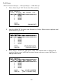
RESERVED PRESET
Description
Some Preset numbers are reserved to special functions.
Function
<Call> [95] <Enter> :
<Call>[131~134]<Enter> :
<Call>[141~148]<Enter> :
<Call>[151~158]<Enter> :
<Call>[161~162]<Enter> :
<Shot>[161~162] <Enter> :
<Call>[170]<Enter> :
<Call>[171]<Enter> :
<Call>[174]<Enter> :
<Call>[175]<Enter> :
<Call>[176]<Enter> :
<Call>[177]<Enter> :
<Call>[178]<Enter> :
<Call>[179]<Enter> :
<Call>[190]<Enter> :
<Call>[191]<Enter> :
<Call>[192]<Enter> :
<Call>[193]<Enter> :
<Call>[194]<Enter> :
Enters into OSD menu
Runs Pattern Function 1~4
Runs Swing Function 1~8
Runs Group Function 1~8
Sets Relay Output 1~2 to OFF
Sets Relay Output 1~2 to ON
Sets Camera BLC Mode to OFF
Sets Camera BLC Mode to ON
Sets Camera Focus Mode to AUTO
Sets Camera Focus Mode to Manual
Sets Camera Focus Mode to SEMI-AUTO
Sets Day&Night Mode to AUTO
Sets Day&Night Mode to NIGHT
Sets Day&Night Mode to DAY
Sets OSD Display Mode to AUTO
(Except Privacy Mask)
Sets OSD Display Mode to OFF
(Except Privacy Mask)
Sets OSD Display Mode to ON
(Except Privacy Mask)
Sets all Privacy Mask Display to OFF
Sets all Privacy Mask Display to ON
PRESET
Function
Max 127 positions can be stored as Preset position. The Preset
number can be assigned from 1~128, but 95 is reserved for starting
OSD menu. Camera characteristics (i.e. White Balance, Auto
Exposure) can be set up independently for each preset. Label should
be blank and ”Camera Adjust” should be set to ”GLOBAL” as default.
All characteristics can be set up in OSD menu
Set Preset
<Preset>[1~128 ] <Enter> (Except [95])
Run Preset
<Call>[1~128 ] <Enter> (Except [95]) To delete Preset, use OSD menu.
Delete Preset
<Dome Camera Setup>→<Preset Setup>→<Ctrl Preset>
11
SWING
Function
By using Swing function, you can make camera to move between 2
Preset positions repeatedly. When swing function runs, camera moves
from the preset assigned as the 1st point to the preset assigned as the
nd
2 point in CW (Clockwise) direction. Then camera moves from the
preset assigned as the 2nd point to the preset assigned as the 1st point
in CCW (Counterclockwise) direction.
In case that the preset assigned as the 1st point is same as the preset
nd
assigned as the 2 point, camera turns on its axis by 360° in CW
(Clockwise) direction and then it turns on its axis by 360° in CCW
(Counterclockwise) direction. Speed can be set up from 1° /sec to
180° /sec.
Set Preset
To set Swing, use OSD menu.
<Dome Camera Setup> <Swing Setup>
Run Swing
E.g.: Run the first swing <Call>[141]<Enter>
E.g.: Run the second swing <Call>[142]<Enter>
Delete Swing
To delete Swing, use OSD menu.
<Dome Camera Setup>→<Swing Setup>→<Clear Swing>
PATTERN
Function
Pattern Function is that a camera memorizes the path (mostly curve
path) by joystick of controller for assigned time and revives the path
exactly as it memorized. 4 Patterns are available and Maximum 1200
communication commands can be stored in a pattern.
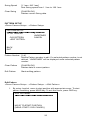
Setup Pattern
<Dome Camera Setup>→<Pattern Setup>→<Edit Pattern>
Pattern editing screen is displayed as bellow.
EDIT PATTERN1
[NEAR: SAVE / FAR: DELETE]
0 / 0 / X1 / N
12
Movement by Joystick and preset movement can be memorized in
a pattern.
The rest memory size is displayed in progress bar.
To save the recording, press NEAR key and to cancel, press FAR
key.
Method 2) OSD Using OSD Menu: See the section “How to use OSD
Menu".
Run Pattern
E.g.) Run Pattern 1: <Call>[131]<Enter>
E.g.) Run Pattern 2: <Call>[132]<Enter>
Delete Pattern
Use OSD menu to delete Pattern
<Dome Camera Setup>→<Pattern Setup>→<Ctrl Pattern>
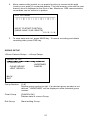
GROUP
Function
The group function allows running sequence of Presets, Pattern
and/or Swings Max 8 group can be stored. Each group can have max
20 action entities which can be preset, pattern or swing Preset speed
can be set up and the repeat number of Pattern & Swing can be set up
in Group setup. Dwell time between actions can be set up also.
Set Group
Use OSD Menu to create a Group
Run Group
Ex) Run Group 1: <Call>[151]<Enter>
Ex) Run Group 2: <Call>[152]<Enter>
Delete Group
Use OSD Menu to delete
<Dome Camera Setup>→<Group Setup>→<Clear Group>
13
OTHER FUNCTIONS
Power Up Action This function enables to resume the last action executed before power
down. Most of actions such as Preset, Pattern, Swing and Group are
available for this function but jog actions are not available to resume.
Auto Flip
In case that tilt angle arrives at the top of tilt orbit (90º), zoom module
camera keep moving to opposite tilt direction (180º) to keep tracing
targets. As soon as zoom module camera passes through the top of tilt
direction (90º), images should be reversed automatically and F
appears in screen. If this function is set to OFF, tilt movement range is
0~95º.
Parking Action
This function enables to locate the camera to specific position
automatically if operator doesn't operate the controller for a while. The
Park Time can be defined as an interval from 1 minute to 4 hours.
Privacy Zone
Mask
To protect privacy, MAX. 4 Privacy Masks can be created on the
arbitrary position to hide objects such as windows, shops or private
house. With Spherical Coordinates system, powerful Privacy Zone
Mask function is possible.
Global/Local
Image Setup
WB (White Balance) and AE (Auto Exposure) can be set up
independently for each preset. There are 2 modes, "Global" mode &
"Local" mode. The Global mode means that WB or AE can be set up
totally and simultaneously for all presets in "ZOOM CAMERA SETUP"
menu. The Local mode means that WB or AE can be set up
independently or separately for each preset in each preset setup
menu. Each Local WB/AE value should activate correspondingly when
camera arrives at each preset location. During jog operation, Global
WB/AE value should be applied. All Local WB/AE value does not
change although Global WB/AE value changes.
Semi-Auto
Focus
This mode exchanges focus mode automatically between Manual
Focus mode and Auto Focus mode by operation. Manual Focus mode
activates in preset operation and Auto Focus mode activates during
jog operation With Manual mode at presets, Focus data is memorized
in each preset in advance and camera calls focus data in
correspondence with presets as soon as camera arrives at a preset. It
should shorten time to get focuses Focus mode changes to Auto
Focus mode automatically when jog operation starts.
14
HOW TO USE OSD MENU
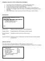
OSD DISPLAY OF MAIN SCREEN
P/T/Z Info
Current Pan/Tilt angle in degree, zoom magnification and a compass
direction.
Camera ID
Current Camera ID (address)
Action Title
Follovangs are possible Action-Titles and their meaning. "SET
PRESET ×××"
When Preset××× is stored "PRESET×××" When camera reach to
Preset ×××
"PATTERN ×" When Pattern × is in action
“ SWG×/PRESET×××” When Swing × is in action
"UNDEFINE D" When undefined function is called to run
Preset Label
The label stored for specific Preset.
Alarm Input
This information shows current state of Alarm Input. If an Input point is
ON state it will show a number corresponding to each point If an Input
point is OFF state, ' - ' will be displayed
Ex) Point 2&3 of inputs are ON, OSD will show as below
Image Flip
Shows that images are currently reversed by Auto Flip Function.
15
GENERAL RULES OF KEY OPERATION FOR MENU
The menu items surrounded with ( ) always has its sub menu.
For all menu level, to go into sub menu, press NEAR key.
To go to up-one-level menu, press FAR key.
To move from items to item in the menu, use joystick in the Up/Down or
Left/Right. To change a value of an item, use Up/Down of the joystick in the
controller.
Press NEAR key to save values and Press FAR key to cancel Values.
MAIN MENU
SPEED DOME CAMERA SYSTEM
INFORMATION
<DISPLAY SETUP>
<DOME CAMERA SETUP>
<SYSTEM INITIALIZE>
EXIT
System Info
Displays system information and configuration.
Display Setup
Enable/Disable of OSD display on Main Screen
Dome Camera
Setup
Configure various functions of this camera.
System Initialize Initializes system configuration and sets all data to factory default
configuration
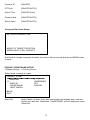
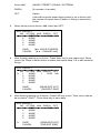
DISPLAY SETUP
This menu defines Enable/Disable of OSD display on Main Screen.
If an item is set to be AUTO, the item is displayed only when the value of it is changed.
DISPLAY SETUP
CAMERA ID
ON
PTZ INFORMATION
AUTO
ACTION TITLE
AUTO
PRESET LABEL
AUTO
ALARM INPUT
AUTO
<SET NORTH DIRECTION>
<PRIVACY ZONE>
BACK
EXIT
16
Camera ID
[ON/OFF]
PTZ Info
[ON/OFF/AUTO]
Action Title
[ON/OFF/Auto]
Preset Label
[ON/OFF/AUTO]
Alarm Input
[ON/OFF/AUTO]
Compass Direction Setup
SET NORTH DIRECTION
MOVE TO TARGET POSITION
[NEAR:SAVE / FAR: CANCEL]
Set North to assign compass direction as criteria. Move camera and press NEAR button
to save.
PRIVACY ZONE MASK SETUP
<Display Setup>→<Privacy Zone>
Select area in image to mask
PRIVACY ZONE
MASK NO
DISPLAY
CLEAR MASK
<EDIT MASK>
1
UNDEFINED
OFF
CANCEL
BACK
EXIT
Mask No.
Select Mask number. If the selected mask has already data, camera
moves as it was set. Otherwise, “UNDEFINED” will be displayed under
“Mask No”.
17
Display
[ON/OFE]
Sets if camera makes mask shows or not on images
Clear Mask
[CANCEL/OK]
Deletes data in the selected Mask No.
Privacy Zone Area Setup
<Display Setup>→<Privacy Zone>→<Edit Mask>
Move camera to area to mask. Then the menu to adjust mask size will be displayed.
EDIT MASK 1
MOVE TO TARGET POSITION
[NEAR:SELECT / FAR: CANCEL]
Privacy Zone Size Adjustment
Adjust mask size. Use joystick or arrow buttons to adjust mask size.
EDIT MASK 1
[ : ADJUST MASK WIDTH]
[ : ADJUST MASK HEIGHT]
[NEAR: SAVE / FAR: CANCEL]
(Left/Right)
(Up/Down)
Adjusts mask width.
Adjusts mask height.
18
CAMERA SETUP
<Dome Camera Setup>→<Camera Setup>
Setup the general functions of zoom camera module.
ZOOM CAMERA SETUP
FOCUS MODE
SEMIAUTO
DIGITAL ZOOM
ON
LINE LOCK
OFF
<WHITE BALANCE SETUP>
<AUTO EXPOSURE SETUP>
BACK
EXIT
Focus Mode
[AUTO/MANUAL/SEMIAUTO]
Sets camera focus mode.
SEMIAUTO Mode
This mode exchanges focus mode automatically between Manual
Focus mode and Auto Focus mode Manual Focus mode activates in
preset operation and Auto Focus mode activates when jog operation
starts. With Manual mode at presets, Focus data is memorized in each
preset in advance and camera calls focus data in correspondence with
presets as soon as camera arrives at a preset.
Digital Zoom
[ON/OFF]
Sets digital zoom function to ON/OFF. If this is set to OFF, optical
zoom function runs but zoom function stops at the end of optical zoom
magnification.
Line Lock
[ON/OFF]
If Line lock sync is ON, video signal is synchronized with AC power.
Video can be fluctuated after setting is changed.
White Balance Setup
<Dome Camera Setup>→<Camera Setup>→<White Balance Setup>
WB SETUP - GLOBAL
WB MODE
RED ADJUST
BLUE ADJUST
AUTO
-------
BACK
EXIT
WB Mode
Red Adjust
Blue Adjust
[AUTO/MANUAL]
In Manual mode, Red and Blue level can be set up manually.
[10~60]
[10~60]
19
Auto Exposure Setup
<Dome Camera Setup>→<Camera Setup>→<Auto Exposure Setup>
AE SETUP - GLOBAL
BACKLIGHT
DAY/NIGHT
BRIGHTNESS
IRIS
SHUTTER
AGC
SSNR
SENS-UP
OFF
AUTO1
25
AUTO
ESC
NORMAL
MIDDLE
<AUTO>
BACK
EXIT
Backlight
[ON/OFF]
Sets Backlight Compensation
Day/Night
[AUTO1/AUTO2 DAY/NIGHT]
AUTO1 exchanges Day/Night mode faster than
AUTO2.
Brightness
[0~100]
Adjusts brightness of images. Iris, Shutter Speed and Gain are
adjusted automatically in correspondence with this value
IRIS
[AUTO/MANUAL(0~100)]
If Iris is set to Auto Iris should have highest priority in adjusting AE and
Shutter Speed should be fixed. If Iris is set to Manual, Iris should be
fixed and Iris has lower priority in adjusting AE, in comparison with
others.
Shutter Speed
[ESC/A. Flicker/Manual (x 128~1/120000 sec )]
If Iris is set to Manual and Shutter Speed is set to ESC, Shutter Speed
should have highest priority. If Shutter Speed is set to A. Flicker, to
remove Flicker, Shutter Speed should be set to 1/100 secretary for
NTSC and 1/120 for PAL.
AGC
[OFF/NORMAL/HIGH]
Enhances image brightness automatically in case that luminance level
of image signal is too low.
SSNR
[OFF/LOW/MIDDLE/HIGH]
Enhances images by deducting noises when gain level of images is
too high.
Sens-Up
[AUTO(2~128)/OFF]
Activates Slow Shutter function when luminance of Image (signal) is
too dark. It is possible to set up the maximum number of frames piled
up one on another by Slow Shutter function
20
MOTION SETUP
<Dome Camera Setup>→<Motion Setup>
Setup the general functions of Pan/Tilt motions.
MOTION SETUP
MOTION LOCK
OFF
PWR UP ACTION
ON
AUTO FLIP
ON
JOG MAX SPEED
120/SEC
JOG DIRECTION
INVERSE
FRZ IN PRESET
OFF
<PARKING ACTION SETUP>
<ALARM INPUT SETUP>
BACK
EXIT
Motion Lock
[ON/OFF]
Group. It is possible only to run those functions. To set up and delete
those functions, enter into OSD menu.
Power Up Action [ON/OFF]
Refer to “Other Functions” section on page 14.
Auto Flip
[ON/OFF]
Refer to “Other Functions” section on page 14.
Jog Max Speed
[1º /sec~360º /sec]
Sets maximum jog speed. Jog speed is inversely proportional to zoom
magnification. As zoom magnification goes up, pan/tilt speed goes
down.
Jog Direction
[INVERSE/NORMAL]
If you set this to 'Inverse', the view in the screen is moving same
direction with jog tilting. If 'Normal' is selected, the view in the screen is
moving reversely.
Freeze In Preset [ON/OFF]
At start point of preset movement, camera starts freezing the image of
start point. Camera keeps displaying the image of start point during
preset movement and does not display the images which camera gets
during preset movement. As soon as camera stops at preset end point,
camera starts displaying live images which it gets at preset end point.
This function availability should be different by models.
21
Parking Action Setup
<Dome Camera Setup>→<Motion Setup>→<Parking Action Setup>
If Park Enable is set to ON, camera runs assigned function automatically if there is no
PTZ command during assigned ''Wait Time''.
PARKING ACTION SETUP
PARK ENABLE
WATI TIME
PARK ACTION
OFF
00:10:00
HOME
BACK
EXIT
Park Enable
[ON/OFF]
Wait Time
[1 minute ~ 4 hours]
The time is displayed with "hh:mm:ss" format and you can change this
by 1 min unit.
Park Action
[HOME/PRESET/PATTERN/SWING/GROUP]
HOME
Camera moves to home position if there is no PTZ command during
assigned "Wait Time".
Alarm Input Setup (For Outdoor PTZ, SS10W-C65H)
<Dome Camera Setup>→<Motion Setup>→<Alarm Input Setup>
Match the Alarm sensor input to one of Preset positions. If an external sensor is
activated, camera will move to corresponding preset position when this item is
predefined.
ALARM INPUT SETUP
ALARM1 TYPE
ALARM2 TYPE
ALARM3 TYPE
ALARM4 TYPE
ALARM1 ACT
ALARM2 ACT
ALARM3 ACT
ALARM4 ACT
N.OPEN
N.OPEN
N. OPEN
N.OPEN
NOT USED
NOT USED
NOT USED
NOT USED
BACK
EXIT
22
Alarm x Type
[Normal OPEN/Normal CLOSE]
Sets sensor input type.
Alarm x Action
[Not USED/PRESET1~128]
Assign counteraction preset position to each alarm input.
PRESET SETUP
<Dome Camera Setup>→<Preset Setup>
PRESET SETUP
PRESET NO
CLR PRESET
<EDIT SCENE>
<EDIT LABEL>
CAM ADJUST
1
CANCEL
LABEL 123
GLOBAL
BACK
EXIT
Preset Number
[1~128] (Except [95])
If a selected preset is already defined, camera moves to pre- defined
position and preset characteristics such as Label and Relay Outputs
show on monitor. If a selected preset is not defined. "UNDEFINED"
shows on monitor.
Clear Preset
[CANCEL/OK]
Delete current Preset data.
Edit Preset
Scene
Redefine current Preset scene position (i.e. PTZ)
Edit Preset
Label
Edits Label to show on monitor when preset runs
MAX. 10 alphabets are allowed
CAM Adjust
[GLOBAL/LOCAL]
WB (White Balance) and AE (Auto Exposure) can be set up
independently for each preset. There are 2 modes, "Global" mode &
"Local" mode. The Global mode means that WB or AE can be set up
totally and simultaneously for all presets in "Z00M CAMERA SETUP"
menu. The Local mode means that WB or AE can be set up
independently or separately for each preset in each preset setup
menu. Each Local WB/AE value should activate correspondingly when
camera arrives at each preset location. During jog operation, Global
WB/AE value should be applied. All Local WB/AE value should not
change although Global WB/AE value changes. If “Local” is selected,
Menu to set WB/AE shows on Monitor.
23
Edit Preset Scene
<Dome Camera Setup>→<Preset Setup>→<Edit Scene>
EDIT SCENE – PRESET1
MOVE TO TARGET POSITION
[NEAR: SAVE / FAR: CANCEL]
1.
2.
3.
Using Joystick, move camera angle to desired position.
By pressing NEAR key, save current PTZ data.
Press FAR key to cancel.
Edit Preset Label
<Dome Camera Setup>→<Preset Setup>→<Edit Label>
EDIT LABEL – PRESET1
[
]
-------------1234567890
ABCDEFGHI
JKLMNOPQR
STUVWXYZ
abcdefghIjkl
mnopqrstuvw
xyz<>-/.
OK
CANCEL
1.
Edits label to show on monitor when camera arrives at presets. In Edit Label
menu, a reverse rectangular is cursor As soon as finishing selecting alphabet,
cursor moves to the next digit
2.
Using Left/Right/Up/Down of joystick, move to an appropriate character from
the Character set. To choose that character, press the NEAR key.
If you want to use blank, choose Space character (" "). If you want to delete
a character before, use back space character ("").
24
3.
If you complete the Label editing, move cursor to "OK" and press NEAR key
to save completed label. To abort current change, move cursor to "Cancel"
and press NEAR key.
SWING SETUP
<Dome Camera Setup>→<Swing Setup>
SWING SETUP
SWING NO
1ST POS
2ND POS
SWING SPEED
CLEAR SWING
1
NOT USED
NOT USED
30/SEC
CANCEL
BACK
EXIT
Swing Number
[1~8]
Selects Swing number to edit. If a selected Swing has not defined,
st
nd
"NOT USED" is displayed in 1 position and 2 position.
1st Position
2nd Position
[PRESET 1~128] (Except [95])
Set up the 2nd position for Swing function. If a selected preset is not
defined, "UNDEFINED" will be displayed as shown below:
When swing function runs, camera moves from the preset assigned
st
nd
as the 1 point to the preset assigned as the 2 point in CW
(Clockwise) direction. Then camera moves from the preset assigned
as the 2nd point to the preset assigned as the 1st point in CCW
(Counterclockwise) direction. In case that the preset assigned as the
1st point is same as the preset assigned as the 2nd point camera
turns on its axis by 360º in CW direction and then it turns on its axis
by 360º in CCW direction.
25
Swing Speed
[1 /sec~180 /sec]
Sets Swing speed from 1 /sec to 180 /sec.
Clear Swing
[CANCEL/OK]
Deletes current Swing data.
PATTERN SETUP
<Dome Camera Setup>→<Pattern Setup>
PATTERN SETUP
PATTERN NO
CLR PATTERN
<EDIT PATTER>
1
UNDEFINED
CANCEL
BACK
EXIT
Pattern Number [1~4]
Selects Pattern number to edit. If a selected pattern number is not
defined, “UNDEFINED” will be displayed under selected pattern
number.
Clear Pattern
[CANCEL/OK]
Deletes data in current pattern.
Edit Pattern
Starts editing pattern.
Edit Pattern
<Dome Camera Setup>→<Pattern Setup>→<Edit Pattern>
1.
By using Joystick, move to start position with appropriate zoom. To start
pattern recording, press NEAR key. To exit this menu, press FAR key.
EDIT PATTERN1
MOVE TO START POSITION
[NEAR: START / FAR: CANCEL]
26
2.
Move camera with joystick or run preset function to memorize the path
(mostly curve path) in a selected pattern. The total memory size and the rest
memory size is displayed m the form of bar. Maximum 1200 communication
commands can be stored in a pattern.
EDIT PATTERN1
MOVE TO START POSITION
[NEAR: SAVE / FAR: DELETE]
X0/0/1/N
3.
To save data and exit, press NEAR key .To cancel recording and delete
recording data, press FAR key.
GROUP SETUP
<Dome Camera Setup>→<Group Setup>
GROUP SETUP
GROUP NO
CLEAR GROUP
<EDIT GROUP>
1
UNDEFINED
CANCEL
BACK
EXIT
Group Number
[1~8]
Selects group number to edit. If a selected group number is not
defined, “UNDEFINED” will be displayed under selected group
number.
Clear Group
[CANCEL/OK]
Deletes data in current Group.
Edit Group
Starts editing Group.
27
Edit Group
<Dome Camera Setup>→<Group Setup>→<Edit Group>
1. Press Near key in "NO" list to start Group setup.
EDIT GROUP 1
NO. ACTION ###
1
NONE
2
NONE
3
NONE
4
NONE
5
NONE
SAVE
CANCEL
2.
[NEAR:EDIT]
Note that MAX.20 Functions are allowed in a Group. Move cursor up/down and
press Near key to set up.
EDIT GROUP 1
NO. ACTION ###
1
NONE
2
NONE
3
NONE
4
NONE
5
NONE
SAVE
CANCEL
3.
DWELL OPT
DWELL OPT
[NEAR:EDIT ACT]
[FAR:EDIT:END]
Setup Action, Dwell time and Option. Note that selected item is displayed in
reverse. Move cursor Left/Right to select items and move cursor Up/Down to
change each value.
EDIT GROUP 1
NO. ACTION ###
1
NONE
2
NONE
3
NONE
4
NONE
5
NONE
SAVE
CANCEL
DWELL OPT
[: MOVE CURSER]
[ : CHANGE VAL]
28
4.
Action ###
[NONE / PRESET / SWING / PATTERN]
DWELL
[0 seconds~4 minutes]
OPT
Option
It should be preset speed when preset is set in Action and
the number of repeat when Pattern or Swing is selected in
Action.
Setup items such as Action, ###, Dwell and OPT.
EDIT GROUP 1
NO. ACTION ### DWELL OPT
1
PRESET 1
00:03 360
2
NONE
3
NONE
4
NONE
5
NONE
SAVE
CANCEL
5.
[: MOVE CURSER]
[ : CHANGE VAL]
After finishing setting up an Action, Press Near key to one-upper-level. Move
cursor Up/ Down to select Action number and repeat Step 1~4 to edit selected
Group.
EDIT GROUP 1
NO. ACTION ### DWELL OPT
1
NONE
1
00:03 360
2
NONE
3
NONE
4
NONE
5
NONE
SAVE
CANCEL
6.
[NEAR:EDIT ACT]
[FAR:EDIT END]
After finishing setting up all Action, Press FAR key to exit. Then cursor should
be moved to" SAVE ", Press Near key to save data.
EDIT GROUP 1
NO. ACTION ### DWELL OPT
1
NONE
1
00:03 360
2
NONE
3
NONE
4
NONE
5
NONE
SAVE
CANCEL
[NEAR:EDIT ACT]
[FAR:EDIT END]
29
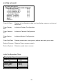
SYSTEM INITIALZE
SYSTEM INITIALIZE
CLEAR ALL DATA
CLR DISPLAY SET
CLR CAMERA SET
CLR MOTION SET
CLR EDIT DATA
REBOOT CAMERA
REBOOT SYSTEM
SAVE
CANCEL
NO
NO
NO
NO
NO
NO
NO
Clear All Data
Deletes all configuration data such as display camera, motion set,
and so on.
Clear Display
Set
Initializes Display Configuration
Clear Camera
Set
Initializes Camera Configuration
Clear Motion
Set
Initializes Motion Configuration
Clear Edit Date
Deletes preset date, swing data, pattern data and group data
Reboot Camera Reboots Zoom camera module
Reboot System
Reboots speed dome camera
Initial Configuration Table
Display Configuration
Camera ID
ON
PTZ Information
AUTO
Action Title
AUTO
Preset Label
AUTO
Alarm Input
AUTO
North Direction
Pan 0
Privacy Zone
Undefined
30
Camera Configuration
Focus Mode
Focus Mode
Digital Zoom
Digital
Zoom
Line Lock
Line Lock
White Balance
White
Balance
Backlight
Backlight
Day & Night
Day & Night
Brightness
Brightness
Iris
Iris
Shutter
Shutter
AGC
AGC
SSNR
SSNR
SENS-UP
SENS-UP
Motion Configuration
Motion Lock
OFF
Power Up Action
ON
Auto Flip
ON
Jog Max Speed
120/sec
Jog Direction
INVERSE
Freeze In Preset
OFF
Park Action
OFF
Alarm Action
OFF
User Edit Data
Preset 1~28
Swing 1~8
Pattern 1~4
Group 1~8
Undefined
Undefined
Undefined
Undefined
31
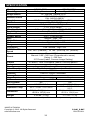
SPECIFICATION
Model
Mount Type
Image Sensor
Effective Pixels
Resolution
S/N Ratio
Zoom
Focal Length
Min. Illumination
Day & Night
Iris
Shutter Speed
AGC
White Balance
BLC
Range
Flickerless
SSNR Pan/Tilt
Speed
Preset
Pattern
Swing
Group
Other Functions
Communication
Protocol
Privacy Zone
Alarm Input
OSD
Fan & Heater
Rated Power
Operation Temp.
Dimension
Weight
SS10C-C65H
SS10W-C65H
Ceiling Mount
Arm Type Wall Mount
1/4" Interline Transfer CCD
NTSC: 967(H)×494(V)
PAL: 960(H)×582(V)
650 TV Lines (Color), 700 TV Lines (B/W)
50 dB (AGC Off)
x10 Optical Zoom, x10 Digital Zoom
F1.8, f=3.8~38mm
0.7 Lux (Color) / 0.02 Lux (B/W), 50 IRE
Auto / Day / Night (ICR)
Auto / Manual
1/50 ~ 1/120,000 sec
Normal / High / Off
Auto / Manual (Red, Blue Gain Adjustable)
Low / Middle / High / Off
Selectable
Low / Middle / High / Off
Pan: 360 (Endless) ; Tilt 180 (Auto-flip, 95 (Normal)
Preset: 360/sec
Manual: 0.05~360/sec (Proportional to zoom)
Swing: 1~180/sec
127 Preset (Label, Camera Image Setting)
4 Pattern, 1200 Commands (about 5 minute)/pattern
8 swing
8 groups (20 action entities per group)
Auto flip, Auto parking, Power up action, etc.
RS-485
Pelco-D, Pelco-P selectable
4 Zone
No
4 Input
Menu / PTZ Info, etc.
No
Yes
12V DC / 0.8 A
12V DC / 1.1A
-22F ~ 122F / -30C ~
32°F ~ 104°F / 0C~40C
50C
Ø5.04 x 7.36(H) inches /
Ø7.48 x 5.67(H) inches /
Ø128 x 187(H) mm
Ø190 x 144(H)mm
2.65 lbs / 1.2 kg
5.51 lbs / 2.5 kg
* Specifications are subject to change without notice.
MADE IN TAIWAN
Copyright © 2012. All Rights Reserved.
www.okinausa.com
P-046_P-047
R201303-V11
32