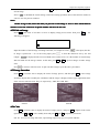
1
V
WED-2000A
WED-2000AV
er
Veterinary Ultrasound Scann
canner
User Manual
Shenzhen Well. D Medical Electronics Co., Ltd.
Content
Manufacturer Information....................................................................................................................................... 1
Preface..................................................................................................................................................................... 2
Copyright......................................................................................................................................................... 2
Statement......................................................................................................................................................... 2
Manufacturer's warranty.................................................................................................................................. 2
Matters need Attention.....................................................................................................................................3
Safety labels.....................................................................................................................................................3
Device safety classification:......................................................................................................................... 4
General tips for device operation.....................................................................................................................4
General Safety Message.................................................................................................................................. 4
Execution Standard(Safety)........................................................................................................................5
Contraindication:........................................................................................................................................ 10
Chapter One Summary...........................................................................................................................................11
1.1 Brief introduction.....................................................................................................................................11
1.2 Range of application................................................................................................................................ 11
1.3 Technical specification.............................................................................................................................12
1.4 Electric principle block diagram..............................................................................................................12
1.5 Basic principle......................................................................................................................................... 12
1.6 Device constituent................................................................................................................................... 13
1.6.1 WED-2000AV standard layout pieces.......................................................................................... 13
1.6.2 WED-2000AV fitting pieces......................................................................................................... 13
1.7 Appearance.............................................................................................................................................. 13
1.8 EMC statement:....................................................................................................................................... 14
Chapter Two Installation........................................................................................................................................15
2.1 Operating environmental requirements....................................................................................................15
2.2 Unpacking inspection.............................................................................................................................. 15
2.3 Installation and disassembly.................................................................................................................... 15
2.3.1 Connection between probe and main unit.....................................................................................15
2.3.2 Installing and disassembling battery.............................................................................................16
2.4 Power Supply...........................................................................................................................................17
2.4.1 Power supply with adapter............................................................................................................17
2.4.2 Battery Operation..........................................................................................................................17
2.5 Battery Charging......................................................................................................................................17
2.5.1 Charging through the main unit.................................................................................................... 17
2.5.2 Charging through adaptive line (Optional)................................................................................... 18
2.5.3 Charging through auto-charger (Optional)....................................................................................18
Chapter Three Keyboard and Mouse Operation.................................................................................................... 20
3.1 Screen Display......................................................................................................................................... 20
3.2 Keyboard Functions.................................................................................................................................20
3.3 Mouse...................................................................................................................................................... 22
Chapter Four Operation Sequence.........................................................................................................................23
4.1 Power on.................................................................................................................................................. 23
4.2 Diagnose.................................................................................................................................................. 23
4.3 Modify Image Parameters........................................................................................................................23
4.3.1 Frequency Setting......................................................................................................................... 24
4.3.2 Gain Setting.................................................................................................................................. 24
4.3.3 Modify Brightness and Contrast................................................................................................... 24
4.4 Note......................................................................................................................................................... 24
4.5 Image Process.......................................................................................................................................... 26
4.5.1 Image Storage............................................................................................................................... 26
4.5.2 Pick out Image.............................................................................................................................. 27
4.5.3 Image Smoothen........................................................................................................................... 27
4.5.4 Color............................................................................................................................................. 27
4.5.5 Measure of perimeter, area and volume........................................................................................28
4.5.6 Statistics of Histogram..................................................................................................................30
4.6 Distance measuring..................................................................................................................................31
4.7 Volume Measuring................................................................................................................................... 32
WED-2000AV Manual/Technical Instructions (V1.20E)
Content
4.8 Heart Rate Measuring(Only in“B/M”and “M” Modes)......................................................................33
4.9 OB calculation......................................................................................................................................... 33
4.10 Image Printing....................................................................................................................................... 39
4.11 Image upload to computer..................................................................................................................... 39
4.12 Power Off...............................................................................................................................................39
Chapter Five Transportation and Storage.............................................................................................................. 40
5.1 Environment requirements on transportation and storage:................................................................... 40
5.2 Transportation.......................................................................................................................................... 40
5.3 Storage..................................................................................................................................................... 40
Chapter Six Check and Maintenance.....................................................................................................................41
6.1 Service life............................................................................................................................................... 41
6.2 Check....................................................................................................................................................... 41
6.3 Main unit maintenance............................................................................................................................ 41
6.4 Probe maintenance...................................................................................................................................41
6.5 Cleansing................................................................................................................................................. 42
6.6 Correct usage of probe.............................................................................................................................42
6.7 Battery information..................................................................................................................................43
6.8 Instrument test and calibration.................................................................................................................44
Chapter Seven Trouble Shooting........................................................................................................................... 45
7.1 Device board principle and hardware pictures.........................................................................................45
7.1.1 LCD TFT display..........................................................................................................................45
7.1.2 Motherboard................................................................................................................................. 45
7.1.3 Key board......................................................................................................................................46
7.1.4 Interface plank.............................................................................................................................. 47
7.1.5 Probes........................................................................................................................................... 47
7.2 WED-2000AV ultrasonic equipment disassembly and assembly............................................................ 47
7.2.1 WED-2000AV ultrasonic equipment componential disassembly................................................. 47
7.2.2 Installation of WED-2000AV........................................................................................................50
7.3 Troubleshooting....................................................................................................................................... 50
7.4 Maintenance of WED-2000AV Digital Ultrasound Scanner................................................................... 50
Appendix A Acoustic output reporting table..........................................................................................................52
Appendix B Obstetrics...........................................................................................................................................55
WED-2000AV Manual/Technical Instructions (V1.20E)
Manufacturer Information
Manufacturer Information
Name: Shenzhen Well.D Medical Electronics Co., Ltd.
Add: F12 N-F13, New Energy B/D, Nanyou Ave., Nanshan District, Shenzhen, 518054
Guangdong, P.R.China
Tel: 0086-755-26073353
0086-755-26073350
Fax: 0086-755-26411198
Email:[email protected]
Authorized agency in EU
Name: Wellkang Ltd.
Add: Suite B, 29 Harley Street LONDON WIG 9QR England, United Kingdom
Tel: +44(20)88168300,88168309,79934346,79276844
Fax: +44(20)76811874
Web: www.CE-marking.com
www.CE-marking.org
www.CEmarking.org
E-mail: [email protected]
CE mark
WED-2000AV Manual/Technical Instructions (V1.20E)
1
Preface
Preface
Copyright
This publication, including pictures and illustrations, is property of Shenzhen Well. D Medical Electronics Co.,
Ltd. and under protection of international copyright law.
Version: V1.20E
P/N No.: WED-20-09001EV
Statement
Information in this document are not annotated to change. The manufacture shall not state nor observe any
warranty basing on this point, and definitely give up any implied warranty basing on any special purpose of
selling or making benefit.
Without previous written permission from the producer, this document must not be photocopied, reproduced or
translated into other languages.
We preserve the right of revision on this document without still further notice.
Some pictures in this manual, which are schematic diagrams for indication only, may disaccord with the real
object, and then the real object should be regarded as the final.
are trade marks of Shenzhen Well. D Medical Electronics Co., Ltd. Any abuse of these trade marks
without permission will be sued to assume legal responsibility according to laws.
Manufacturer's warranty
Shenzhen Well. D Medical Electronics Co., Ltd. assumes the responsibility for device security, reliability and
performance only under the preconditions that the disassembly, assembly and maintenance of the device are all
performed by its assigned professional and the device is used strictly in compliance with the operation manual.
Shenzhen Well. D Medical Electronics Co., Ltd. ensures a guarantee period within a year and a half since the
delivery day and promises there is no problem with the new device in material and technology. Within the
guarantee period, Shenzhen Well. D Medical Electronics Co., Ltd. will maintain the device and replace the parts
of non-man-made damages free of charge. But will not repair or replace the device surface if it is damaged.
This guarantee is only available for failures occurred when the device is operated in compliance with the
operation manual. And the guaranteed device can only be used in the prescribed range given in manual.
This guarantee excludes losses or damages caused by external reasons such as thunder struck, earthquake, theft,
unsuitable use or abuse and refitting the device.
Shenzhen Well. D Medical Electronics Co., Ltd. shall not be responsible for damages caused by other devices or
arbitrary connection to other devices.
Shenzhen Well. D Medical Electronics Co., Ltd. shall not be responsible for losses, damages or injuries caused
by delayed service request.
When there is problem with the products, please contact Shenzhen Well. D Medical Electronics Co., Ltd. and
explain the device model, serial number, date of purchase and the problem.
2
WED-2000AV Manual/Technical Instructions (V1.20E)
Preface
Matters need Attention
To ensure operational safety and long-term stable equipment performance, please read this operation manual
closely and understand the device functions, operation and maintenance at all points before operating the device,
especially contents of "Warning", "Caution" and "Note".
Misoperation or inobservance of the instructions given by manufacturer or its agents may result in device
damage or personal injury.
The following convention works through this manual to lay special emphasis on some information.
"Warning":
Stands for neglect of it will cause severe personal injury, death or realized property loss.
"Caution": Stands for neglect of it will cause slight personal injury or property damage.
"Note": to remind user of installation, operation or maintenance information. These information is very
significant but with no risk. Any warning against dangers shall not be contained in NOTE.
Safety labels
Device labels explanation:
Attention!consult accompanying documents
Switch on the main electrical supply
Switch off the main electrical supply
Signal output
USB port
IPX7
Protected against the effects of immersion
ClassⅡ device
Mouse
Probe socket
Packing and transportation labels explanation:
Handle with care
Temperature limit
Upwards
Limited layers of stowage
Protect against wetness
Protect against heat
WED-2000AV Manual/Technical Instructions (V1.20E)
3
Preface
:
Device safety classification
classification:
●According to the degree of safety of application in the presence of a flammable anaesthetic mixture with air or
with oxygen or nitrous oxide:
WED-2000AV can not be used in situation of mixture of inflammable anaesthesia gas and air or nitrous oxide.
●Classify as per work system:
WED-2000AV is continuous operation device.
●Classify as per harmful liquid leakage:
The main unit of WED-2000AV is conventional device; the probe is a device of resistance to flooding.
●Classify according to shockproof type:
WED-2000AV is GroupⅡ device powered by external adapter.
●Classify according to shockproof level:
WED-2000AV is Type B Applied part
General tips for device operation
In operation
1.Heat radiation holes are strictly prohibited to be covered.
2.After closedown, do not switch on the device within 2 - 3 minutes.
3.On scanning, if any abnormal case is found, stop scanning immediately and shut down the device.
After operation
1. Power off the device.
2. Pull out the plug from power supply socket instead of pulling the cable.
3. Clean off the couplant on the probe with soft medical sterilized cotton ball.
General Safety Message
Safety of the operator and patients and reliability of the device are taken into consideration during designing and
producing, the following safety precaution must be implemented:
1. The device shall be operated by qualified operating staff or under their instructions.
2. Do not open the device and change the parameters without permission. If necessary, please turn to for
Shenzhen Well.D Medical Electronics Co., Ltd. or its authorized agent for service.
3. The device has already been regulated into its optimal performance. Do not adjust any preset control or switch
unless operate as per instructions in the manual.
4. If there is device failure, please shut down the device at once and contact for Shenzhen Well.D Medical
Electronics Co., Ltd. or their authorized agent.
5. If it is needed to connect the device with other company’s' electronic or mechanical devices,please contact
Shenzhen Well. D Medical Electronics Co,. Ltd. before connection.
6. Device operation, storage and transportation environment
Environmental requirements on normal operation:
a) Environment temperature range: 0℃ ~ +40℃
4
WED-2000AV Manual/Technical Instructions (V1.20E)
Preface
b) Relative humidity range: ≤80%
c) Atmosphere pressure range: 70KPa~ 106KPa
Environment requirements on device storage and transportation:
a) Environment temperature range: - 20℃~ +55℃
b) Relative humidity range: <80%(20℃)
7. Do not hit the fragile TFT-LCD display. If it cracks, deal carefully with it in case the liquid crystal gets into
eyes or mouths.
8. Must not hit the inner rechargeable lithium battery nor throw it into fire in case it trigger an explosion;Do not
short circuit the battery output electrodes in case the battery be damaged; and please use the original binding
charger to charge the battery. More over, because used battery will cause environment pollution, please handle
the battery correctly for recovery processing.
9. Must not disassemble the power supply adapter. If failures happen, it should be handled by the professional;
the charging output can only be used for charging the battery of the device, any improper use on other battery
may cause explosion, fire and other unexpected hazards.
10. Must not short circuit the output of the adapter,a long term short circuit shall result in adapter damage.
11. Please use standard power cord as the input line of the network power supply for the adapter to reduce risk.
12. Shenzhen Well. D Medical Electronics Co., Ltd. shall not take any responsibility for any risk resulted from
propelled / unauthorized re-fitment by the users.
13.To disconnect the device from the power supply network by unplug the adapter from the power supply
network.
14.Ultrasound might cause hazard on human body so long time radiation should be avoided. Refer to appendix A
and C for sound output parameters.
15. To disconnect power supply and equipment, please unplug the power Adapter plug.
(Safety
)
Execution Standard
Standard(
Safety)
● Safety Standard
In China
WED-2000AV Manual/Technical Instructions (V1.20E)
5
Preface
Standard Number
Standard Name
GB9706.1-1995
Medical Electronic Device, Part I:General safety Requirements
GB9706.9-1997
Medical Electronic Device, Specialized Safety Requirements for Medical
Ultrasound Diagnosis and Monitor Device
In Europe
Standard Number
Standard Name
IEC60601-1:1988
+A1:1991 +A2:1995
Medical Electronic Device, Part I:General safety requirements
IEC60601-1-2:2004
Medical Electronic Device, Part I to II: General Safety Requirement -- Parallel
Standard: Requirement and Testing of Electromagnetism Compatibility
IEC60601-1-4:2000
Medical Electronic Device, Section I to IV: A Program-controlled Medical
Electronic System
IEC60601-2-37:2001
Medical Electronic Device, Specialized Safety Requirements for Medical
Ultrasound Diagnosis and Custodial Care Facility
IEC61157:1992
Requirements for the Declaration of the Acoustic Output of Medical Ultrasound
Diagnostic Apparatus
● EMC
EMC(Electromagnetic Compatibility)Standard
Standard Number
6
Standard Name
IEC60601-1-2:2001
Electromagnetic Compatibility for Medical Systems, comprised of:
IEC61000-4-2:2001
Electrostatic Discharge Immunity
IEC61000-4-3:2002
Radiated Field Immunity
IEC61000-4-4:A2/2001
Electrical Fast Transient/Burst Immunity
IEC61000-4-5:2001
Voltage Surge Immunity
IEC61000-4-6:2001
Immunity to Conducted Disturbance, Induced by Radio-frequency Fields
IEC61000-4-8:2001
Power Frequency Magnetic Fields
IEC61000-4-11:2001
Voltage Dips, Shorts and Variations
WED-2000AV Manual/Technical Instructions (V1.20E)
Preface
Guidance and manufacture
manufactureˊss declaration – electromagnetic emissionsFor all EQUIPMENT and SYSTEMS
Guidance and manufacture
manufactureˊss declaration – electromagnetic emission
The WED-2000AV Ultrasonic Diagnostic Equipment is intended for use in the
electromagnetic environment specified below. The customer of the user of the WED-2000AV
Ultrasonic Diagnostic Equipment should assure that it is used in such and environment.
Emission test
Compliance
Electromagnetic environment - guidance
RF emissions
CLSPR 11
Group 1
The WED-2000AV Ultrasonic Diagnostic
Equipment uses RF energy only for its
internal function. Therefore, its RF
emissions are very low and are not likely to
cause any interference in nearby electronic
equipment.
RF emission
CLSPR 11
Class B
The specimen of WED-2000AV is suitable
for any facility, including household and
public low voltage supply network for
households.
Harmonic emissions
IEC61000-3-2
Class B
Voltage fluctuations/
flicker emissions
IEC 61000-3-3
Complies
WED-2000AV Manual/Technical Instructions (V1.20E)
7
Preface
Guidance and manufacture
manufactureˊss declaration – electromagnetic immunityFor EQUIPMENT and SYSTEMS that are not LIFE-SUPPORTING
Guidance and manufacture
manufactureˊss declaration – electromagnetic immunity
The WED-2000AV Ultrasonic Diagnostic Equipment is intended for use in the electromagnetic environment
specified below. The customer or the user of WED-2000AV Ultrasonic Diagnostic Equipment should assure that it
is used in such an environment.
Immunity
IEC 60601
Compliance
Electromagnetic environment - guidance
test
test level
level
Portable and mobile RF communications equipment should
be used no closer to any part of the WED-2000AV
Ultrasonic Diagnostic Equipment, including cables, than
the
recommended separation distance calculated from the
equation applicable to the frequency of the transmitter.
Recommended separation distance
3.5
d=[ V1 ] P
3.5
3Vrms
Conducted RF
d=[ E1 ] P
IEC 61000-4-6
0.5V
3V/m
Radiated RF
IEC 61000-4-3
80 MHz to 800 MHz
150 kHz to 80 MHz
3V/m
80 MHz to 2.5GHz
7
d=[ E1 ] P
800 MHz to 2.5GHz
Where P is the maximum output power rating of the
transmitter in watts (W) according to the transmitter
manufacturer and d is the recommended separation
distance in metres (m).
Field strengths from fixed RF transmitters, as determined
by an electromagnetic site survey, a should be less than the
compliance level in each frequency range. b
Interference may occur in the vicinity of equipment marked
with the following symbol:
NOTE1 At 80 MHz and 800 MHz, the higher frequency range applies.
NOTE2 These guidelines may not apply in all situations. Electromagnetic propagation is affected by absorption
and reflection from structures, objects and people.
a
Field strengths from fixed transmitters, such as base stations for radio (cellular/cordless) telephones and land
mobile radios, amateur radio, AM and FM radio broadcast and TV broadcast cannot be predicted theoretically with
accuracy. To assess the electromagnetic environment due to fixed RF transmitters, an electromagnetic site survey
should be considered. If the measured field strength in the location in which the WED-2000AV Ultrasonic
Diagnostic Equipment is used exceeds the applicable RF compliance level above, the WED-2000AV Ultrasonic
Diagnostic Equipment should be observed to verify normal operation. If abnormal performance is observed,
additional measures may be necessary, such as reorienting or relocating the WED-2018 Ultrasonic Diagnostic
Equipment.
b
8
Over the frequency range 150 kHz to 80 MHz ,field strengths should be less than 0.5V/m.
WED-2000AV Manual/Technical Instructions (V1.20E)
Preface
Recommended separation distances between portable and mobile
RF communications equipment and the EQUIPMENT or SYSTEMfor EQUIPMENT or SYSTEM that are not LIFE-SUPPORTING
Recommended separation distances between portable and mobile
RF communications equipment and the WED-2000AV Ultrasonic Diagnostic Equipment
The WED-2000AV Ultrasonic Diagnostic Equipment is intended for use in an electromagnetic
environment in which radiated RF disturbances are controlled. The customer or the user of the
WED-2000AV Ultrasonic Diagnostic Equipment can help prevent electromagnetic interference by
maintaining a minimum distance between portable and mobile RF communications equipment
(transmitters) and the WED-2000AV Ultrasonic Diagnostic Equipment as recommended below,
according to the maximum output power of the communications equipment.
Rated maximum output
power of transmitter
Separation distance according to frequency of transmitter
(m)
(W)
150 kHz to 80 MHz
d=
d=[
3.5
V1
] P
80 MHz to 800 MHz
d=
d=[
3.5
E1
] P
800 MHz to 2.5 GHz
d=
d=[
7
E1
] P
0.01
0.70
0.12
0.23
0.1
2.21
0.37
0.74
1
7
1.17
2.33
10
22.14
3.69
7.38
100
70.00
11.67
23.33
For transmitters rated at a maximum output power not listed above, the recommended separation
distanced in metres (m) can be estimated using the equation applicable to the frequency of the
transmitter ,where P is the maximum output power rating of the transmitter in watts (W) according
to the transmitter manufacturer.
NOTE 1 At 80 MHz and 800 MHz ,the separation distance for the higher frequency range applies.
NOTE 2 These guidelines may not apply in all situations. Electromagnetic propagation is affected
by absorption and reflection from structures, objects and people.
WED-2000AV Manual/Technical Instructions (V1.20E)
9
Preface
Guidance and manufacture
manufactureˊss declaration – electromagnetic immunity –
for all EQUIPMENT and SYSTEMS
Guidance and manufacture
manufactureˊss declaration – electromagnetic immunity
The WED-2000AV Ultrasonic Diagnostic Equipment is intended for use in the electromagnetic environment
specified below. The customer or the user of WED-2000AV Ultrasonic Diagnostic Equipment should assure
that it is used in such an environment.
Immunity test
Electrostatic
discharge(ESD)
IEC61000-4-2
Electrical fast
transient/burst
IEC 61000-4-4
Compliance level
Electromagnetic
guidance
±6kV contact
±6kV contact
±8 kV air
±8 kV air
Floors should be wood, concrete or
ceramic tile. If floors are covered with
synthetic material, the relative
humidity should be at least 30%.
IEC 60601 test level
±2kV
for
±2kV
for
±1kV for
supply lines
power
dofferemtoal
mode
±1kV dofferemtoal
IEC 61000-4-5
±2kV common
mode
mode
<5% UT
(>95% dip in UT)
for 0.5 cycle
voltage variations on
power supply input
lines
IEC 61000-4-11
40% UT
(60% dip in UT)
for 5 cycle
70% UT
(30% dip in UT)
for 25 cycle
a typical commercial or hosital
environment.
Mains power quality should be that of
(>95% dip in UT)
a typical commercial or hosital
for 0.5 cycle
environment. If the user of the
WED-2000AV Ultrasonic Diagnostic
40% UT
Equipment requires continued
(60% dip in UT)
operation during power mains
for 5 cycle
interrutions, it is recommended that
the WED-2000AV Ultrasonic
Diagnostic Equipment be powered
from an uninterruptible power supply
or a battery.
Power frequency
field
Mains power quality should be that of
<5% UT
<5% UT
(>95% dip in UT)
for 5 sec
(50Hz) magnetic
Mains power quality should be that of
a typical commercial or hosital
environment.
input/output lines
Surge
interruptions and
Power
3A/m
IEC 61000-4-8
3A/m
frequency
magnetic
fields
should be at levels characteristic of a
typical location in a typical
commercial or hospital environment.
NOTE UT is the a.c. mains voltage prior to application of the test level.
:
Contraindication
Contraindication:
It is suggested not to probe the part with wound or acute inflammation to avoid cross infection.
10
–
power
supply lines
±1kV
Voltage dips, short
environment
WED-2000AV Manual/Technical Instructions (V1.20E)
Chapter One Summary
Chapter One Summary
1.1 Brief introduction
The device adopts technologies such as microcomputer control and digital scanning converter (DSC), large
dynamic broadband low-noise preamplifier, logarithmic compression, dynamic filtration, edge enhancement etc.
to ensure legible, stable and high resolution images.
◆Four display modes: B, B+B, B+M, M; Can realize image real time display, frozen, zoom; Hospital, Name,
Age, Sex annotation; Measure Distance, circumference, area, volume, heart rate, gestation age;Image gray
scale 256 levels.
◆Combined power supply mode of AC adapter and built-in Li-ion chargeable battery, 3 battery charging modes
and the specialized brownout mode enables more lasting battery operation.
◆5 inches TFT-LCD display and programmable device (FPGA) and surface mounted technology (SMT) make
this device compact and light in weight.
◆PAL-D video output.
◆With mouse mouthpiece.
◆Jet molding enclosure with hand-held structure makes it convenient for out diagnoses.
◆The device consists of mainframe, probe and adapter.
◆Standard configuration is S2/3.5MHz mechanical sector scanning probe or S3/3.5MHz waterproof mechanical
sector scanning probe, with S2/5.0MHz mechanical sector scanning probe and S3/5.0MHz waterproof
mechanical sector scanning probe for option.
◆The device is proved safe and effective via clinical validation.
1.2 Range of application
Suitable for diagnosis on swines, equines,bovines, sheeps, cats and dogs and other animals.
WED-2000AV Manual/Technical Instructions (V1.20E)
11
Chapter One Summary
1.3 Technical specification
Model
WED-2000AV
Probes
Displayed Depth (mm)
Maximal detect depth (mm)
Resolution
(mm)
Lateral
Axial
Blind area (mm)
Geometric
Horizontal
position
Precision (%) Vertical
Monitor size (inch)
Display modes
Image gray scale
Depth (mm)
Measure functions
Character display
Battery capacity
Mainframe power
consumption
Adapter power consumption
Mainframe
weight(Excl.probe)
Standard
3.5MHzMechanical sector
scan
192
≥140
≤4 (depth≤80)
≤5 (80<depth≤130)
≤2 (depth≤80)
≤8
Optional
5.0MHzMechanical sector
scan
192
≥80
≤20
≤15
≤10
≤10
≤3 (depth≤60)
≤1 (depth≤60)
≤8
5.0 TFT-LCD
B、B+B、B+M、M
256 levels
120~190
Distance, circumference, area, volume, heart rate, gestation age
Hospital, Name, Age, Sex
2200mAh
13W at non-charging operation / 25W at charging operation
80VA
800g
1.4 Electric principle block diagram
Probe
Receiving
Regulation,
Focusing and
Amplifying
Transmitting
Regulation
Control
Digital Video
Video
Composing
Frame
RAM
B Mode
Address
Crystal
Oscillator
CPU
Diagram and
Character
D/A
Gray
Scales
Read and
Write
Control
Mouse
Key Board
Correlatio
n
Processing
A/D
M Mode
Address
Monitor
Picture 1-1 Electric principal block diagram
1.5 Basic principle
B-ultrasound works in this following procedure: different tissues of human body possess different densities and
speeds of transmission of ultrasound, i.e. different acoustic impedance (product of media density and sound
speed).when piezo-chip (transductor) gets certainly regulated electric impulse, it will produce ultrasound with
certain frequency. when this ultrasound (sound energy) is injected into human body, different organ surfaces will
12
WED-2000AV Manual/Technical Instructions (V1.20E)
Chapter One Summary
produce reflection echo, the different size reflection is received by the transductor which emitted ultrasound and
is changed into electric impulse, when this electric impulse is amplified, demodulated, digital scanned, shifted
and some other handling, video standard signal is produced and organ cross-sectional images are displayed on
the monitor.
1.6 Device constituent
1.6.1 WED-2000AV standard layout pieces
�
�
�
�
�
Mainframe(containing a piece of Li-ion battery)
S2/3.5MHz mechanical sector scan probe or S3/3.5MHz waterproof mechanical sector scanning probe
Manual/ technical instructions
Power adapter(containing power cord)
Mouse
1.6.2 WED-2000AV fitting pieces
�
�
�
�
�
S2/5.0MHz mechanical sector scan probe, S3/5.0MHz waterproof mechanical sector scanning probe
Video printer
Li-ion battery
Car charger
Charging adaptation wire
:
Warning
Warning:
Please select spare parts models prescribed above. The manufacturer will
not assume the risks such as safety problem, non-expected drop of EMC
performance that cause by arbitrary adoption of spare parts out of
prescription.
1.7 Appearance
Picture 1-2.WED-2000AV front sketch map
Picture 1-3. WED-2000AV side mouthpiece sketch map
WED-2000AV Manual/Technical Instructions (V1.20E)
13
Chapter One Summary
Picture 1-4 WED-2000AV underside turn-button sketch map
Picture 1-5 WED-2000AV back side sketch map
1.8 EMC statement:
WED-2000AV shan't affect the basic performance of radio service and other equipments, and can work well in
the expected and declared electromagnetic environments.
:
Warning
Warning:
Working in intense electromagnetic environment, its images may be
interfered and the diagnoses may be affected. By this time, stop operating
to avoid misdiagnosis. Reuse after the electromagnetic interference is
removed.
:
Warning
Warning:
Working when the device is overlapped with other devices or close to
others might cause unexpected EMC problems; If they have to be put
together, please check every one to ensure no one is affected by unexpected
EM coupling.
:
Warning
Warning:
Replacement of parts that not according with specs or connection to other
devices might cause unexpected EMC problems. The possibility of
unexpected EM coupling effect should be testifies carefully.
14
WED-2000AV Manual/Technical Instructions (V1.20E)
Chapter Two Installation
Chapter Two Installation
2.1 Operating environmental requirements
1. Environment temperature range:0℃~+40℃
2. Relative humidity range:≤80%
3. Atmosphere pressure range:70KPa~106KPa
When using, avoid strenuous vibration, keep it away from devices with high field, intense magnetic field or high
voltage; avoid strong sunlight blazing down on the display; keep the device well-ventilated, moisture proof and
dustproof.
2.2 Unpacking inspection
After unpacking, check the device according to "Packing List" and install it according to requirements and
methods described in "Installation" after affirm that there is no shipping damage.
:
Warning
Warning:
If there is breakage at unpacking check, it is banned to use the device to ensure
security.
2.3 Installation and disassembly
2.3.1 Connection between probe and main unit
Probe jack lies in the top of the right side, insert the probe into the jack correctly and turn it clockwise and wound
it. There is only one probe jack which can connect to all the supported optional probes.
Dismounting is the reverse process of installation.
WED-2000AV probe placement and take-out
Insert the probe into the probe supporter to set it and push to slide the probe form the supporter to take out it
(Picture 2-1).
Picture 2-1. WED-2000AV probe placement and take-out
WED-2000AV Manual/Technical Instructions (V1.20E)
15
Chapter Two Installation
:
Warning
Warning:
Avoid by all means unplugging or plugging the probe connector at state of log on
in case the probe and main unit be damaged.
Once the probe is connected with the main unit, do not unplug nor plug it at
discretion in case poor contact happen.
:
Warning
Warning:
Must not touch the contact pin in the probe connector.
:
Warning
Warning:
The probe should be protected from felling off or crashing and the manufacturer
assumes no responsibility for this kind of hazard.
Warning
:
Warning:
Please handle the device carefully.
2.3.2 Installing and disassembling battery
Install WED-2000AV battery: Set the battery into the battery slot and move the battery release key on its back to
top till the battery is inserted completely and then release the key (refer to Picture 2-2).
Battery release key
Picture 2-2. WED-2000AV battery installation
Disassemble WED-2000AV battery: It is the reverse process of installation (refer to Picture 2-3).
Battery release key
Picture 2-3. WED-2000AV battery disassemble
16
WED-2000AV Manual/Technical Instructions (V1.20E)
Chapter Two Installation
2.4 Power Supply
The device provides two automatic switch-over modes to supply power: adapter and built-in battery.
2.4.1 Power supply with adapter
1.Check the input power cord plug of the adapter to see if it matches the EPS outlet.
2.Check the EPS to see if it is in the specified range and the power cord to see if it is connected well.
3.Check the adaptor to see if it works well: Plug the power cord into the AC input outlet, switch on the power
switch of the outlet, if the DC output indicating light turns on green, it works well.
4.Shut the power switch of the outlet.
5.Insert the DC output plug of the adapter into the DC14V outlet in the right side of the device, switch on the
outlet.
6.Switch on the main unit, the device is available now.
2.4.2 Battery Operation
1.Install the battery correctly into the main unit.
2.Push down the main unit power switch to power on the main unit, the power indicator will turn on.
3.The device can start operation.
:
Note
Note:
When the main unit under-voltage indicator turn into red, it means the battery is
running up and needs charging.
Warning
:
Warning:
It is prohibited to use any other power supply except the standard adapter as the
external power supply for the main unit.
2.5 Battery Charging
There are 3 ways to charge the battery.
2.5.1 Charging through the main unit
1.Install the battery correctly into the main unit.
2.Insert the plug of “
3.Connect power cord of "
” of the adapter into the DC14V interface on the side.
" of the adapter to the EPS.
4.No matter the main unit is power on or shut down, when the "
" indicator flickers, the adapter is charging
the battery, When the "
" indicator turns off from flickering, the battery is fully charged (Picture 2-4).
WED-2000AV Manual/Technical Instructions (V1.20E)
17
Chapter Two Installation
Picture 2-4. WED-2000AV charging
2.5.2 Charging through adaptive line (Optional)
1.Take out the battery from the main unit or take out the spare battery.
2.Connect the "
" terminal of the adapter to the charging terminal of the battery with charging adaptive
line.
3.Connect power cord of "
" terminal of the adapter to the EPS.
4.When the "
" indicator light on the adapter turns into red, the battery is in charging; When the
"
" indicator light turns into green from red, the battery is fully charged.(Refer to Picture 2-5).
Picture 2-5. WED-2000AV charging adaptive line
2.5.3 Charging through auto-charger (Optional)
1.Take out the battery from the main unit or take out the spare battery.
2. Connect the flat end marked with an arrow of the auto-charger to the charging terminal of the battery.
3. Plug the other end of the auto-charger into the cigar lighter socket.
4. When the "Charging" indicator light on the adapter turns into red, the battery is in charging; When the
"Charging" indicator light turns into green, the battery is fully charged(Refer to 2-11).
18
WED-2000AV Manual/Technical Instructions (V1.20E)
Chapter Two Installation
Picture 2-6. WED-2000AV charging through auto-charger
Tips:
~14V/1.5A
1. The input voltage of the auto-charger is DC9
DC9~
14V/1.5A..
2. The output voltage of the auto-charger is DC12.6V/1A
DC12.6V/1A..
3. The operations and storage environment are the same as those of the main unit.
WED-2000AV Manual/Technical Instructions (V1.20E)
19
Chapter Three Keyboard and Mouse Operation
Chapter Three Keyboard and Mouse Operation
3.1 Screen Display
Name of Hospital
Patient Name
Patient Age
Sex
Date and Time
Battery Indicator
Type of probe
3
Frequency
Value of gain and
image sharpening
Illumination and
Contrast
Fake color of image
Color of Characters
Background Color
Scanning Area
of the Probe
Depth
Picture 3-1. Screen Display
3.2 Keyboard Functions
The following is the keyboard of WED-2000AV
Picture 3-2. Operation Panel
Press it to shift between the states of freeze and real time.
Notes: If
FREEZE exists in the right lower corner, the image is frozen.
M/0 ~ BM/9 are multifunction keys
As character keys
keys:
● During menu operation, they are used for selecting the sub-menu.
20
WED-2000AV Manual/Technical Instructions (V1.20E)
Chapter Three Keyboard and Mouse Operation
● While inputting Age and Time in the menu, they are used as numbers.(Further details are available)
●Use M/0
M/0.
/1
/1. +/2
+/2. B/7
B/7. BB/8
BB/8. BM/9 to input names of the hospital and the patient.(Further details are
available.)
As functions keys
keys:
M/0 Mode Display
In B/M mode, no matter in the state of real time or freeze, press it, then there will be mode display, with an M
on the screen.
In non-B/M mode, press it to display the menu of image disposal and press
to cancel.
/1
In the state of real-time scanning, press it to alter the image multiple. The range is:120~190,with 7 levels.
+/2 Measure Mark
Press it in Freeze state, then “+” will be displayed on the screen. Use direction keys or mouse to move it.
(Refer to next chapter for further details)
▲3 ~ ▼6 Direction Keys
They are used for moving the cursor. ▲3. ▼6 are used for altering the scanning depth in the real-time state in
“B”mode(the same function as
/1 ). Press ▲3 to increase the depth, while press ▼6 to decrease, with the
current depth displayed in the lower right-hand corner. While inputting names of patients and hospitals, use
▲3. ▼6 to turn the page up and down.
5 .
4 are used for activating the parameters on the right side, with activated parameters lighten. At this
time, use▲3. ▼6 to alter.
B/7 B Mode Display
In the state of freeze or real time, press it to enter B mode ( The default is single B).
BB/8 Double B Mode Display
In the state of freeze or real time, press it to enter double B mode. There are two B picture on the screen. One
is “Freeze” picture, the other is “Real time” one; Repeat pressing, the picture can shift between “Freeze” and
“Real time”. Press
, then both of them show freeze picture.
BM/9 B and M Mode Display
In the state of freeze or real time, press it twice to enter B/M mode. Both pictures are displayed on the screen.
The left is B real-time picture, and the right is M one. Repeat pressing, you can shift between B and M. On B
picture, there is a vertical line composed by equidistant dots which is named sample line.
WED-2000AV Manual/Technical Instructions (V1.20E)
21
Chapter Three Keyboard and Mouse Operation
Single B
BB
BM
M
Picture 3-3.Four kinds of mode display
Obstetrics
Press it in freeze mode of“B”or“BB”to display the obstetrics menu. Press the number keys and further details
are available in the following instructions. To exit, please press
.
Measure Reference
Along with +/2
+/2. M/0 and direction keys, the measure of distance, perimeter, area and histogram can be done.
Further details are available in the following chapter.
Press it, the note menu is displayed. Then press the number keys to enter the sub-menu. Refer to the following
chapter for further details. Press
to exit.
Clean Screen
Press it to clean marks, notes and results. In menu status, press it to quit the menu.
Press it when the device crashes by accidents or operation mistakes, then the device can return to normal.
3.3 Mouse
As a supplement to the keyboard, the mouse can make the measure quicker and more convenient.
Three-button mouse is available for this device. The left, middle and right buttons all have their specific
functions.
Left:
● The cursor is displayed when you press it and enter distance measure.
Middle:
●Press it in real-time or freeze mode, the function is the same as
.
Right:
●It can identify the start and end place of the cursor in the mode of distance measure and shift between the
two.
●It can identify the start place of cursor in perimeter and area measure by free-hand method and complete the
measure.
●Its function is the same as
22
in perimeter and area measure by ellipse method.
WED-2000AV Manual/Technical Instructions (V1.20E)
Chapter Four Operation Sequence
Chapter Four Operation Sequence
4.1 Power on
Press Power, the indicator is lighten and starting interface appears. At this moment, press any key(except
and
) to enter scanning state. Modify the gain to satisfy the reader.
Picture 4-1. Start Interface
Notes: You can adjust the observation angle for better displaying effect, for the effect is associated with
the observation angle.
:
Attention
Attention:
Screen tearing or disorder might occur after being switched on. This is due
to unstable battery level or environmental electromagnetic interference.
Please reset to fix this problem.
Attention:
The cooling holes in the back can not be covered, or the device may be
damaged by overheat.
4.2 Diagnose
Spread medical sonic couplant on diagnostic area, and attach the probe sound window closely to it. The
ultrasound image of the tissue section will be displayed on the screen. Move the probe and find out the
right place. Adjust the gain to maintain the best image.
Attention
1. Excessive force is not allowed while the probe touching diagnostic area,
for it may damage the probe.
2. Use appropriate probe to diagnose.
4.3 Modify Image Parameters
The parameters include frequency of probe, gain, brightness and contrast. Press 5
or
4 in real-time
state, one of them is lightened. Use▲3 and ▼6 to set the parameters and they are displayed in the upper
right-hand corner.
WED-2000AV Manual/Technical Instructions (V1.20E)
23
Chapter Four Operation Sequence
4.3.1 Frequency Setting
Press 5
or
4 in real-time state to lighten frequency in the upper right-hand corner and use ▲3 and ▼6
to adjust, with the range of 2.5MHz. 3.5MHz. 5.0MHz.
4.3.2 Gain Setting
Press 5
or
4 in real-time state to lighten gain in the upper right-hand corner and use ▲3 and ▼6 to
adjust, with the range between 0 and 60。
4.3.3 Modify Brightness and Contrast
Press 5
or
4 to lighten “
.
”,and use ▲3 and ▼6 to modify the brightness and contrast.
4.4 Note
In freeze state,press
,and the note menu is displayed(as follow). You can complete these functions:
V1.20
0.NAME
1.AGE
2.SEX
3.COMMENT
4.TIME
5.HOSP
6.LANGUAGE
7.ERASE
8.DEFAULT SET
9.BEEP-ON
V1.20:Software Version Number
● Press M/0 , select“0.NAME”to input the patient name,as follow:
PLEASE ENTER NAME:
0-A 1-B 2-C 7-D 8-E 9-F
There are 26 letter keys and space key under it and use ▲3. ▼6 to turn page up and down. Correspondant
characters can be displayed when pressing the number key, with the maximum of 15 letters. Press
clean the wrong character. Press
to
to confirm and exit after inputting, or you can directly press
to exit from inputting.
● Press
/1 , select“1.AGE” to input the patient age, the maximum iuput number is 3 bits, the input
interface is as follow:
PLEASE ENTER AGE:
Press
to confirm and exit after inputting, or you can directly press
● Press +/2 ,select“2.SEX”to input patient sex, the interface is as follow:
24
WED-2000AV Manual/Technical Instructions (V1.20E)
to exit from inputting.
Chapter Four Operation Sequence
PLEASE ENTER SEX:
1.MALE
2.FEMALE
Use number key /1 to select“1.MALE”,press +/2 to select“2.FEMALE”。
● Press ▲3 , and select“3.COMMENT”to enter Image Note. White cursor will appear on the screen,
together with 26 letter keys and space key at the bottom.
and
are used to turn page up and down.
Correspondant characters can be displayed when pressing the number key, with the maximum of 15 letters.
Press
to clean the wrong character. Press
directly press
to confirm and exit after inputting, or you can
to exit from inputting.
4 ,and select“4.TIME”to modify time and date. The interface is as follow:
● Press
YY-MM-DD
HH-MM-SS
For example:2006-9-22
9:35:30 are input as follow:
YY-MM-DD
060922
HH-MM-SS
093530
Press
to confirm and exit after inputting, or you can directly press
● Press 5
to exit from inputting.
,and select“5.HOSP”to input hospital name,as follow
PLEASE ENTER HOSP:
0-A 1-B 2-C 7-D 8-E 9-F
You can refer to patient input for details. There is a maximum of 18 characters in the name.
● Press ▼6 ,and select“6.LANGUAGE”. The interface is as follow:
PLEASE ENTER LANGUAGE:
1.CHINESE
Press
2.ENGLISH
/1 to select Chinese or +/2 to select English.
WED-2000AV Manual/Technical Instructions (V1.20E)
25
Chapter Four Operation Sequence
● Press B/7 ,and select“7.ERASE”to clean all image storage, as follow:
ERASE ALL STORAGE?
1.YES 2.NO
Press
/1 to confirm. During the process, “ERASING...” will appear in the upper left-hand corner and at
the same time, other operations are unavailable. When it disappears, the storage is erased.
Press +/2 to abandon and exit.
Attention:
…” exists
),other operations
Before the erasing is completed,( when
when““ERASING
ERASING…”
exists)
are not allowed, for they may damage the device.
● Press BB/8 and select “8.DEFAULT SET” to restore the factory settings.
● Press BM/9 and select “9.BEEP-ON” to switch on or switch off the key voice.
:When
, no number input is available. In note menu,
Notes
Notes:
When0.NAME.. 3.COMMENT.. 5.HOSP are input
input,
press
to exit directly.
4.5 Image Process
M/0 in freeze state, the menu is as follow. There are functions of save, pick out, image smoothen,
PressM/0
color and measure of area, volume and histogram.
V1.20
0.SAVE
1.SVLOAD
2.IMAGEPROC
3.COLOR
4.AREA-VOLM
5.HISTOGRAM
V1.20: Software version number
4.5.1 Image Storage
128 images can be stored even when the power is off.
●Press M/0 to display image process menu after a satisfying image is frozen, and then press M/0 to store,
with its number displayed in the upper left-hand corner, such as “SAVING……05”. When the storage is
complete, the number disappears. Press
to return to real-time state.
●This device can store the maximum of 128 images and they are numbered automatically in order. For
example: If there are No. 01—20 images,the next storage is numbered 21;When the storage is full(reaches
128), the following will appear:
STORAGE IS FULL. ERASE NO.01?
1.YES
26
2.NO
WED-2000AV Manual/Technical Instructions (V1.20E)
Chapter Four Operation Sequence
It is the hint for whether to erase No. 01;Press
current image.
/1 to replace;Press +/2 to abandon the storage of the
Select “2.NO”to abandon the current storage. In the later storing operation, there will be hint for whether to
erase No. 02. The process continues.
:
Notes
Notes:
●If the storage is full, and at this time you pick out certain image to store it. There will be hint for
whether to erase the existed one of specific number and store the new one.
4.5.2 Pick out Image
Press M/0 in the mode of real time or freeze to display image process menu. Then press
/1 , the
following will appear:
PLEASE ENTER STORAGE NO.:
Input the number of stored image according to the hint, for example 01. Press
01 image is picked out. ( If it is the wrong input, press
after input, then No.
to clean the characters one by one and
reinput).01/128 is displayed in the lower left-hand corner on the screen. 01 is the number of current image
and 128 stands for the storage volume. At this time, press▲3 or ▼6 to pick out images in other storage
areas.
Press
to return to real-time state. To pick out other images, repeat the above procedures.
4.5.3 Image Smoothen
Press M/0 in real-time state to display the menu of image process, and then press +/2 to select image
smoothen. Repeat this to modify the smoothness and the image is displayed in the upper right-hand corner
of the screen in real-time state. They are respectively:IM0. IM1. IM2. IM3。
Normal
Smooth
4.5.4 Color
Press M/0 in real-time state to display the menu of image process, and press ▲3 to lighten Color on the
right side. Use 5
or 4 to select modify items and press▲3 and ▼6 to adjust the parameters.
IC0. IC1. IC2. IC3 are image fake color, representing respectively grey, red, yellow and blue.
WED-2000AV Manual/Technical Instructions (V1.20E)
27
Chapter Four Operation Sequence
CC0. CC1 are color of characters, representing grey and yellow.
BC0. BC1 are background color, representing grey and blue.
4.5.5 Measure of perimeter, area and volume
Two methods are available.
M/0 in the state of freeze, the menu is displayed on the screen.
●PressM/0
● Press 4 to select 4.AREA-VOLM, and it is displayed as follow:
PLEASE ENTER:
1.FREEHAND
2.ELLIPSE
The first one is Freehand method and the second is Ellipse method.
a.Freehand
a.Freehand:
Keyboard Operation
1. Press /1 to select Freehand method. Then measure cursor appears on the screen. Use direction keys to
move the cursor to the start of the examined spot.
2. Press
3. Press
,and use direction keys to move the cursor along the fringe of the examined area to the end.
again to finish the measuring.
If measuring should be continued, press M/0 and
4 or directly press +/2
+/2,and repeat Step 2-3. You can
get 2 groups of data at most. The results are on the right side of the screen.
Picture 4-2. Illustration of Measuring perimeter and Area(Freehand Method)
C1 and A1 are respectively perimeter and area of the first group;
C2 and A2 are respectively perimeter and area of the second group;
C1/C2 is the ratio of two perimeters;
A1/A2 is the ratio of two areas.
Notes: There are limitations of measuring perimeter and area by keyboard. For more conveniences, you
28
WED-2000AV Manual/Technical Instructions (V1.20E)
Chapter Four Operation Sequence
can use the following Mouse Operation.
Mouse Operation
1. Press
/1 to select Freehand method. The cursor appears on the screen, and then use the mouse to
move the cursor to the starting spot of the examined area;
2. Press right button to move the cursor along the fringe of examined area to the end;
3. Press right button again to complete the measuring of perimeter and area.
If measuring should be continued, press M/0 and
4 or directly press +/2
+/2,and repeat Step 2-3. You can
get 2 groups of data at most. The results are on the right side of the screen.
After the measuring, press Middle button to clean the screen.
b. Ellipse Method
Method:
Keyboard Operation
Press +/2 to select Ellipse method. At this time an ellipse area appears which is called the examined area.
Use direction keys to move this area.
is applied to shift among three functions of direction keys to
adjust the size and angle.
1. Use direction keys to move the examined area to image display area;
2. Press
,and then direction keys to alter the size of the examined area. Press ▲3 and ▼6 to decrease
or increase the area vertically, and then press 5
3. Press
again , then use 5
examined area and press
4. Press
or
or
4 to decrease or increase the area horizontally;
4 to adjust the angle. Press 5
to revolve anticlockwise the
4 to revolve clockwise;
again,the function of direction keys will be shifted into Move the Examined Area;
5. After the location, size, angle of the examined area are confirmed, the measuring can be done .
If measuring should be continued, press M/0 and
4 or directly press +/2
+/2,and repeat Step 1-5. You can
get 2 groups of data at most. The results are on the right side of the screen.
Picture 4-3. Illustration of Measuring perimeter and Area(Ellipse Method)
WED-2000AV Manual/Technical Instructions (V1.20E)
29
Chapter Four Operation Sequence
C1 and A1 are respectively perimeter and area of the first group;
C2 and A2 are respectively perimeter and area of the second group;
C1/C2 is the ratio of two perimeters;
A1/A2 is the ratio of two areas.
Mouse Operation
Press +/2 to select Ellipse Method. At this time an ellipse area appears which is called the examined area.
Use direction keys to move this area. The right button is applied to shift among three functions of the
mouse to adjust the size and angle;
1. Use the mouse to move the examined area to image display area;
2. Press the right button,and then move the mouse to alter the size of the examined area. Move the mouse
left and right to decrease or increase the area vertically, and then move the mouse up and down to decrease
or increase the area horizontally;
3. Press the right button again , then move the mouse left and right to revolve the examined area
anticlockwise and revolve clockwise;
4. Press the right button again,the function of the mouse will be shifted into Move the Examined Area;
5. After the location, size, angle of the examined area are confirmed, the measuring can be done .
If measuring should be continued, press M/0 and
4 or directly press +/2
+/2,and repeat Step 1-5. You can
get 2 groups of data at most. The results are on the right side of the screen.
After measuring, press the middle button to clean the screen.
Volume measuring is in the later chapter.
4.5.6 Statistics of Histogram
●Press M/0 in freeze mode, the menu is displayed on the screen.
● Press5 to select5.HISTOGRAM,sampling window is displayed. Use direction keys or mouse to move
to certain area, and press
or the right button to complete the counting, with the result on the right side
of the screen, as follow:
X axis stands for grey scale, and y axis
stands for number.
PT stands for the total number of pixels in
the rectangular window.
Gm stands for the grey scale of the curve
at the peak of the y axis.
Pm stands for the number of pixels in Gm
grey scale.
From the above figure, in the rectangular
area, the total number of pixel dots is 10000. At
dray scale 52, there are 327 dots, the most
image pixel dots.
Picture 4-4. Illustration of the histogram statistics
30
WED-2000AV Manual/Technical Instructions (V1.20E)
Chapter Four Operation Sequence
●In the process, press
/1 or +/2 to reduce or enlarge the sampling window. Press
to exit.
4.6 Distance measuring
●Keyboard Operation
Operation:
+/2 in freeze mode, the cursor is displayed on the screen.
1. Press+/2
2. Use direction keys to move the cursor to the starting spot.
3. Press
to confirm the starting spot for distance measuring.
4. Press direction keys, another cursor appears. And move it to the ending spot. Then press
complete the measuring.(Notes: Repeat pressing
/1 to
to shift between the cursor of the starting spot and
the ending spot.)
If the distance measuring needs to be continued, you can repeat step 1-4, with the maximum of 4 groups of
data. The results are displayed on the right side of the screen.
Picture 4-5. Illustration of Distance Measuring
The four groups are respectively D1. D2. D3. D4,in which
D1/D2 is the ratio of D1,D2;
D3/D4 is the ratio of D3,D4.
●Mouse Operation
Operation:
1. Press the left button and the cursor is displayed;
2. Use the mouse to move the cursor to the starting spot;
3. Press the right button to confirm the starting spot;
4. Use the mouse to move, and another cursor appears(cursor of the ending spot). Move it to the ending
spot and press
/1 to complete the measuring.(Notes: Repeat pressing the right button can shift between
the beginning spot and the ending spot of the cursor.)
If the distance measuring needs to be continued, you can repeat step 1-4, with the maximum of 4 groups of
data. The results are displayed on the right side of the screen, as in Picture 4-5.
WED-2000AV Manual/Technical Instructions (V1.20E)
31
Chapter Four Operation Sequence
Press the middle button to clean the screen after the measuring.
4.7 Volume Measuring
Two methods are available to measure the volume.
1. 3 groups of distance data are measured by 3 axis method and the result is obtain by calculation.
The distance should be measured for three times before the volume measuring, and then press M/0 to
obtain the value.
If the data are less than three groups, there will be no value displaying when you press M/0
M/0; If you input
four groups of data and then press M/0 , the value displayed is the calculating result of the first three
groups(D1,D2,D3).
Procedures:(Kidney as example)
1. Catch the cross and longitudinal sections of the kidney respectively and freeze them.
2. Measure the long axis and short axis of the cross section by means of distance measuring.
3. Measure the diameter of the longitudinal section by means of distance measuring.
4. Press M/0 to complete the measuring, with the value of volume in “Vm1”on the right side, as follow:
Picture 4-6. Illustration of volume measuring(3 Axis Method)
2. Measure two groups of perimeter and area by Ellipse Method and obtain the result by calculating.
Procedures:(Kidney as example)
1. Catch the cross and longitudinal sections of the kidney and freeze.
2. Measure the perimeter and area of cross and longitudinal sections.
3. The system will automatically complete the measuring, with the value of volume in “Vm1”on the right
side, as follow:
32
WED-2000AV Manual/Technical Instructions (V1.20E)
Chapter Four Operation Sequence
Picture 4-7. Illustration of Volume Measuring(Ellipse Method)
(Only in
)
4.8 Heart Rate Measuring
Measuring(
in““B/M
B/M””and “M” Modes
Modes)
1.In B/M mode, freeze a satisfying cardiograph.
2. Measure the distance between wave crests of two periods by means of distance measuring method, and 3
groups of data will be displayed in the lower right-hand corner. The marks are respectively:Time T(unit:
ms). Heart Rate HR(unit: /m). Slope EF(unit:mm/s)
B/M Mode
Single M Mode
Picture 4-8. Illustration of Heart Rate Measuring
4.9 OB calculation
The device is capble of measurement on GA of equine, bovine, sheep, swine,cat and dog, and so on.The GA
(GW) can be acquired after measuring GS, BL, HL, SL, USD, HD, BD, CRL etc., among them, the EDD of cat
and dog will be given.
Operation process:
Freeze the image, press
key to display equine, bovine, swine, sheep OB menu; Press
to display cat and dof OB menu, press
key again
key to switch between this two menus as the following figure
shows:
WED-2000AV Manual/Technical Instructions (V1.20E)
33
Chapter Four Operation Sequence
0. EQUINE:GSD
1. BOVINE:BL
2. BOVINE:SL
3. BOVINE:HL
4. SWINE:HL
5. SHEEP:USD
0. CAT:HD
1. CAT:BD
2. DOG:GSD
3. DOG:CRL
4. DOG:HD
5. DOG:BD
Input the number and select the related OB menu and acquire the distance as per distance measurement
method. The corresponding GA result displays behind “G·A=” on screen right, and the EDD displays
behind “EDD=” as given below in details:
Calculate the gestation age according to horse GS
● EQUINE-GSD
EQUINE-GSD:Calculate
Examination steps on equine:
1. Clear off the egesta in rectum.
2. Feel the pregnancy with hand and give a primary estimation and confirm the examing organ with
ultrasound.
3. Hold the probe closely and and put it into rectum and ensure that your hand can feel the coming change
inside recta. Keep hand closing to the back and between the probe and recta wall.
4. The inner construction of equine displays on the screen, bladder lies in the portrait cross place and the
behind is uterine horns and body. From the horizontal view, uterine horns are in shape of round usually.
Move the probe around to acquire a better observation on the joint of uterine horns and body, and then
switch the probe to uterine horns as the following figure shows:
1 Rectum
2 Uterine horns
3 Uterine bodies
4 Ovaries
5 Vaginas
6 Bladders
Picture 4-9. Probe position for uterine and ovaries examination
5. The measurement method of GS diameter is given below and measurement can be done horizontally or
vertically.
Womb
Picture 4-10. Equine GA measurement
34
WED-2000AV Manual/Technical Instructions (V1.20E)
Chapter Four Operation Sequence
6. Confrim the distance value as per distance measurement methods and the corresponding data display
behind “G·A”. With this measurement to set up a chart to find the growth curves to estimate embryo size
and GA.Here GA refers to the duration from the copulation instead of impregnation.
Calculate the gestation age according to bovine BL
● BOVINE-BL
BOVINE-BL:Calculate
Examination steps on bovine:
1. Clear off the egesta in rectum.
2. Feel the pregnancy with hand and give a primary estimation and confirm the examing organ with
ultrasound.
3. Hold the probe closely and and put it into rectum and ensure that your hand can feel the coming change
inside recta. Keep hand closing to the back and between the probe and recta wall.
4. The inner construction of bovine displays on the screen, bladder lies in the portrait cross place and the
behind is uterine horns and body. From the horizontal view, uterine horns are in shape of round usually.
Move the probe around to acquire a better observation on the joint of uterine horns and body, and then
switch the probe to uterine horns as the following figure shows:
1 Rectum
2 Uterine horns
3 Uterine bodies
4 Ovaries
5 Vaginas
6 Bladders
Picture 4-11. Probe position for uterine and ovaries examination
5. To measure the fetus body diameter, select a vertical section first, that is a section from two side to the
neck, chest and abdomen. Body diameter can be acquired when the GA is between 60 to 150 days.
The measurement method of ody diameter is given below:
Body diameter
Picture 4-12. BL measurement
6. Confrim the distance value as per distance measurement methods and the corresponding data display
behind “G·A”.
Calculate the gestation age according to bovine SL
● BOVINE-SL
BOVINE-SL:Calculate
1. Keep the cow standing.
WED-2000AV Manual/Technical Instructions (V1.20E)
35
Chapter Four Operation Sequence
2. Put the probe against the abdomen side center, shift it a little bit left or right and hold it closely against
the skin. Clean the abdomen skin if there is mud to ensure a clear display of the abdominal pelvic structure.
3. The maximum vertical axile of the stomachi should be displayed on the screen. With the time going on,
futus stomachi long axile increases regularly. The measuremenet method is given below:
Heart
Stomach
Picture 4-13. Buvine stomachi measurement
4. Confrim the distance value as per distance measurement methods and the corresponding data display
behind “G·A”.
Calculate the gestation age according to bovine HL
● BOVINE-HL
BOVINE-HL:Calculate
1. Keep the cow standing.
2. Put the probe against the abdomen side center, shift it a little bit left or right and hold it closely against
the skin. Clean the abdomen skin if there is mud to ensure a clear display of the abdominal pelvic structure.
3. The maximum vertical axile of the heart should be displayed on the screen. With the time going on, futus
heart long axile increases regularly. The measuremenet method is given below:
Heart
Picture 4-14. Buvine heart measurement
4. Confrim the distance value as per distance measurement methods and the corresponding data display
behind “G·A”.
Calculate the gestation age according to SWINE HL
● SWINE-HL
SWINE-HL:Calculate
Check routine on pigs:
1. Make the swine in a state of stand.
2. Put the probe, a little bit left or right of the centre, on the ventral abdominal wall closely along the side of
teats and skull to rear leg. If the is mud on this part, clean with water first incase the abdomen pelvic
structure could not be displayed accurately.
36
WED-2000AV Manual/Technical Instructions (V1.20E)
Chapter Four Operation Sequence
Picture 4-15. Swine GA measurement
3. To measure the heart macro-axis, screen should display the maximal longitudinal axis of heart. With the
growth of gestation age, the fetal heart macro-axis increase regularly. Measuring method is given in the
following figure:
Heart
Picture 4-16. Swine Heart measurement
4. Measure selected parameter distance according to distance measurement method, the corresponding
gestation age data will automatically shows behind " G·A ".
-USD
● SHEEP
SHEEP-USD
-USD:: Estimate gestation age according to hilum-spine length of sheep
There are two methods to exam pregnant sheep:
Use the probe to check abdomen. These two methods are the same usful. It is proofed as cording to some
publication that these two methods are the same effective in pregnancy examination.
—
Rectum exmanination is more exact than abdomen examination within first 35 days pregnancy;
—
The two methods are the same effective between 35 to 70 days pregnancy;
—
After 70 days pregnancy, abdomen examination is better because it is more practical when the uterine
becomes large.
Abdomen check:
1. Abdomen examination can be done when the sheep is standing or lying or seating. Put the probe against
the appointed abdomen center where there is no fur.
2. Clean the abdomen skin if there is mud to ensure a clear display of the abdominal pelvic structure.
3. Measure the length of USD.
4. Confrim the distance value as per distance measurement methods and the corresponding data display
behind “G·A”.
WED-2000AV Manual/Technical Instructions (V1.20E)
37
Chapter Four Operation Sequence
Calculate the gestation age according to cat HD
● CAT-HD
CAT-HD:Calculate
Head diameter refers to the maximum inner skull diameter from the side of abdomen to back. This value
can be acquired within 8 month pregnancy.
The HDmeasurement is given below:
Picture 4-17. Cat HD measurement
CAT-BD
Calculate the gestation age according to cat BD
●CAT-BD
CAT-BD:Calculate
After fetal head formed, binary top diameter measurement becomes a routine in ultrasonic examination.The
measuring method is:
1. Fetal head axial plane scanning, look for BPD measuring standard plane from top to bottom.
2. According to distance measurement method to measure distance of selected parameters, the
corresponding gestation age data will automatically show behind " G·A".
● DOG-GSD: Calculate the gestation age according to dog gestation saccus diameter
The method is the same as that of equine.
● DOG-CRL: Calculate the gestation age according to dog CRL
The method is the same as that of cow.
● DOG-HD: Calculate the gestation age according to dog HD
The method is the same as that of cat.
● DOG-BD: Calculate the gestation age according to BD
The method is the same as that of cat.
Tips: After display the OB menu, press
key to exit.
Note
At OB measurement, when the distance is less than the following value, the GA of this
animal will not display. Refer to the following table for detailed data:
38
WED-2000AV Manual/Technical Instructions (V1.20E)
Chapter Four Operation Sequence
EQUINE
D1<6mm
BOVINE–BL
D1<8mm
BOVINE–SL
D1<1mm
BOVINE–HL
D1<3mm
SHEEP
D1<15mm
SWINE
D1<31mm
CAT–HD
D1<15mm
CAT–BD
D1<17mm
DOG–GSD
D1<1mm
DOG–CRL
D1<1mm
DOG–HD
D1<14mm
DOG–BD
D1<16mm
4.10 Image Printing
Use Video line to connect VIDEO IN port in the printer and VIDEO OUT port in the device and operate
according to the instructions of video printer.
1 Image upload to computer
4.1
4.11
Connect the USB communication port of the equipment to the computer's USB port.
The high speed USB2.0 mouthpiece can upload images to the computer at current time.
In the accompanying disc, there are USB device driver and software.
2 Power Off
4.1
4.12
Press Power on the right side to turn the device off.
Notes: There is still some power consumption in power-off state. If the device will not be used in a long
time, the battery should be removed from the main engine and the plug be pulled out.
Attention:
No unplugging and plugging is allowed when the power is still on ; If power-on is
needed after power-off, the interval is better to be 2-3 minutes, or the device may be
damaged.
WED-2000AV Manual/Technical Instructions (V1.20E)
39
Chapter Five Transportation and Storage
Chapter Five Transportation and Storage
5.1 Environment requirements on transportation and storage
:
storage:
Environment temperature range:- 20℃~+55℃
0
Relative humidity range:<80%(20 C)
5.2 Transportation
Signs on the packing box conform to 《 Iconograph and sign of packing, storage and transportation 》
(GB/T191-2008). Simple shockproof establishment is fitted within the box,which apply to aviation, railway,
highway or steamship transportation. Keep dry, avoid inversion and collision.
5.3 Storage
Equipment should be taken out from the packing when storage time exceeds six months,power on it for four
hours, and then pack it correctly and keep it in a warehouse. The device must not be piled, and do not place it
closely against the floor, walls or roof.
Keep it well ventilated, do not expose it to strong sunlight or caustic gases.
40
WED-2000AV Manual/Technical Instructions (V1.20E)
Chapter Six Check and Maintenance
Chapter Six Check and Maintenance
6.1 Service life
Bases on the manufacturer’s design, production related files, this model’s use life is six years. The Product’s
material will gradually aging, if the product continually use over the designed use life, it may bring the problem
of the performance reduced and fault rate raise.
:
Note
Note:
The Discard the device according to local law.
Do not discard it mixing with other household garbage.
:
Warning
Warning:
The manufacturer shall not assume the responsibility of risks caused by
using the device beyond its service life.
6.2 Check
Check the device power cord and probe cable and waterproof cover, if find any damage or breakage, must not
use the device and replace the broken immediately.
Check if the probe and main unit are connected rightly.
Check the adapter EPS regularly, when the supply voltage exceeds specified accommodation limit
( AC100V-240V±10%, 50/60Hz),Do not supply the main unit or charge the battery with adapter.
Check the adapter power cord and probe cable, if find any damage or breakage, replace the broken immediately.
Adapter is the dedicated power of the device, it adopts omniseal insulation design, do not replace it with other
adapters or attempt to open it incase there be any hazard.
6.3 Main unit maintenance
Instrumentation environment should accord with "2.1 operation environmental requirement".
If device enclosure needs cleaning,shutdown the device first and then wipe with alcohol sponges.
Device should not turn on and off frequently.
When the device does not work for a long time, pack the device according to the instructions on the packing.
Store it properly in the warehouse. The storage environment should accord with “5.1 Transportation and storage
environmental requirements".
6.4 Probe maintenance
Probe is an expensive part and frangible. Never hit it or drop it on floor.
Please use medical ultrasound couplant during diagnoses. Do daily inspection on the probe enclosure to see if it
is cracked and avoid liquid leakage to spoil the built-in components
Check the probe regularly to see if it is filled with clean medical castor oil lest the existing air bubbles influence
the image quality. If air bubbles appear, turn the probe oil filler hole up and screw off the sealing screw, turn the
probe slowly to drive the air bubbles to the screw hole, infuse a little bit of castor oil into the screw hole with
syringe with a needle (refer to Picture 6-1), vent the air bubbles and fasten the sealing screw and finally clean
WED-2000AV Manual/Technical Instructions (V1.20E)
41
Chapter Six Check and Maintenance
the oil stain on the probe surface.
Oil injection hole
Probe chip
Scanning direction
Picture 6-1 Mechanical sector scan probe oil injection, and scanning direction
6.5 Cleansing
1.When the enclosure need cleaning, wipe it with soft dry cloths and then wipe gently with sponge dipped with
75% medical alcohol .
:
Warning
Warning:
To prevent accidents, take out the battery when cleaning the main unit
enclosure and separate the device from the power supply network first and
then clean the adapter enclose.
Prevent all the plugs, sockets from water splash or socking.
:
Warning
Warning:
Must not use extender, ethylene oxide or any other organic solvent which
tend to deface the probe's protective foil.
Keep device or probe from any type of liquid's infiltration.
Must not clean device or probe by airing or heating.
:
Caution
Caution:
Please refer to instructions prescribed by the manufacturer closely when
using detergents.
Be careful with cleaning of the display, because it is very easy to scratch
and spoil. Please wipe it with dry soft cloth.
Please do not clean the inner base of the device.
Please do not place the device in liquid.
Do not leave any detergent on the device surface.
Though there will be no chemical reaction between the device enclosure
and most of those detergents, We still suggest no detergent in cleaning lest
the device surface is spoiled.
6.6 Correct usage of probe
In order to prolong probe's service life and obtain optimum performance,follow these instructions:
42
WED-2000AV Manual/Technical Instructions (V1.20E)
Chapter Six Check and Maintenance
1. Periodic inspection on probe cable, socket and acoustic window.
2. Shutdown the device first and then connect or disconnect the probe.
3. Do not drop probe or flint body , and never hit the probe acoustic window, otherwise probe should be
damaged.
4. Never heat the probe.
5. Never bend or pull probe cable, otherwise the internal connection should be broken.
6. Use couplant only on probe header and then clean probe.
7. Inspect probe acoustical window, enclosure and cable seriously after probe cleaning. Never use the probe
again if any crack or breakage is found.
6.7 Battery information
1. The equipment is fitted with rechargeable li-ion battery.
2. For optimum efficiency, the new battery must be charged and discharged (regular service,not enforced
discharging) two or three rounds completely.
3.The battery can be charged and discharged for hundred times,but it will be worn-out. When the work
time shortens apparently, please replace it with a new one.
4. Be sure to use electricity charger appointed by Shenzhen Well.D Electronics CO., Ltd. (i.e. AC adapter)
to charge the battery. Do not connect the battery to the electricity charger (AC adapter) when charging is
not needed. Do not connect the battery to the electricity charger (AC adapter) longer than 10 hours;
otherwise the battery life may shorten. The fully charged battery will discharge by itself if it is long-time
out of use.
5.The battery should be charged and discharged once in every 3 months to prevent it unuseful.
6. Extreme environment temperature (overcooling or overheating) will influence battery charging effect.
Must not charge the battery near the ignition source or under extreme hot condition! Do not use or store
battery near source of heat (such as fire or heater)! If find the battery is leaking or smelling, move the
battery away from the naked flame immediately.
7. Don’t go on using non-serviceable battery and electricity charger (AC adapter).
8. Don't try demounting battery.
9. Don't short circuit the battery.
10. Do not throw the battery into the fire or heat it, otherwise it would trigger an explosion.
11. Do not souse or wet the battery.
12. Do not incorrectly connect the positive and negative polarity.
13. Do not directly connect the battery to wall outlet or car-lit socket.
14. Must not short circuit the positive and negative polarity of the battery with led or other metal objects.
Must not transport nor store the battery with necklace, hair pin or other metal objects.
15. Must not pierce battery shell with nail or other sharp objects, must not hammer nor step on the battery.
16. Must not hit, cast the battery and avoid mechanical shock on it.
WED-2000AV Manual/Technical Instructions (V1.20E)
43
Chapter Six Check and Maintenance
17. Must not bead the battery terminals.
18. Must not decompound the battery in any way.
19. Must not place the battery in microwave oven or pressure vessels.
20. Must not combine the battery with primary battery (such as dry battery) or battery with different
capacity, models and types.
21. Do not use the battery if it is smelling, heating, straining, discolored or with other abnormal phenomena
and remove it from the current consumer or electricity charger immediately and stop using it any longer.
22. Do deal carefully with the discarded battery according to local related waste handling regulations.
6.8 Instrument test and calibration
1. Check the leakage current of the device annually referring to the following data.
Standard
Requirements
Test Items
Continuous
leakage
current under normal
temperature (uA)
Leakage current to
Shell
Leakage current
to Patient
Dielectric
endurance
temperature (V)
under
normal
Normal
≤100
Single Malfunction
≤500
Normal
≤100
Single Malfunction
≤500
A- a2
4000V/1min
No flashover
No breakdown
2. Test the software of obstetrics, area, and circumference measurement; please refer to Appendix B for detailed
data.
44
WED-2000AV Manual/Technical Instructions (V1.20E)
Chapter Seven Trouble Shooting
Chapter Seven Trouble Shooting
7.1 Device board principle and hardware pictures
WED-2000AV Digital Ultrasound Scanner consists of LCD monitor, Motherboard, Interface plank, keyboard,
probe and others.
7.1.1 LCD TFT display
LCD TFT screen basic principle: LCD TFT liquid crystal display technology adopts "active-matrix" as its
driving mode. It is a kind of AM-LCD in active matrix LCD families. There are special light pipes on the back
of TFT which can control each pixel of the display "actively". It utilizes matrix-form electro-crystal electrode
array manufactured with thin film technology to control the On and Off of every display point "actively" by
scanning. The light source penetrates the lower polaroid upwards and transfers in virtue of liquid crystal
molecules. When electrodes are conducted, the electric field will rotate liquid crystal. Because molecular
refractivity of the liquid crystal changes with liquid crystal direction. The result is the deflection polarity of light
is changed when going through liquid crystal molecules, ie. transmissivity of light is changed, thus to achieve
the purpose of displaying by shading and light transmission.
7.1.2 Motherboard
Channel provides voltage pulse for discharging piezoelectric vibrator at the control signal of DSC digi-board
and processes the receiving return signal, that is return signal anterior pole amplification, rectification, aperture
transformation, phase transformation, signal processing, STC control, probe auto-recognition, and then the
postamble is sent to DSC digi-board.
DSC generates control address codes to control the work of channel board and process the return signal digitally:
Signal pre-amplification, DBF, RDA, DRA, DRF, DFS, 8 TGC, frame correlation regulation and so on, together
with character signal, they are synthetised into digital video signal. At last, they are translated into analogous
VGA signal and PAL-D signal via different D/A change-over circuits for displaying.
WED-2000AV Manual/Technical Instructions (V1.20E)
45
Chapter Seven Trouble Shooting
LCD
Keyboard socket
Motherboard picture
:
Warning
Warning:
Please do not adjust potentiometers on boards arbitrarily because each
index is set to be optimal when leaving factory.
If need to adjust, it must be done by our authorized technicians with the
help of special instruments.
7.1.3 Key board
Key board basic principle: Key board adopts matrix serial keyboard structure. The motherboard fulfils key plate
scanning. PIC SCM system keeps scanning on the matrix keyboard to check if there is keystroke. If yes, PIC
SCM will detect the key assignment code and pass it to main SCM of the main board via serial port, then the
main SCM of main board carries out command operation according to key assignments. PIC SCM has the
functions of both electric quantity indication and alarm control.
Motherboard Control signal line
Keyboard connection socket picture
46
WED-2000AV Manual/Technical Instructions (V1.20E)
Chapter Seven Trouble Shooting
7.1.4 Interface plank
Interface plank picture
7.1.5 Probes
The probe is a transducer, when transmitting, it can change electric energy into mechanical energy (sound
energy), when receiving, it can change mechanical energy into electric energy.
Probe picture
7.2 WED-2000AV ultrasonic equipment disassembly and assembly
7.2.1 WED-2000AV ultrasonic equipment componential disassembly
Remove these 4
screws.
WED-2000AV Manual/Technical Instructions (V1.20E)
47
Chapter Seven Trouble Shooting
Remove these 5
screws.
Remove the signal
connection.
48
WED-2000AV Manual/Technical Instructions (V1.20E)
Chapter Seven Trouble Shooting
Remove these 4
screws.
Remove these 4
screws.
Remove these 4
screws.
WED-2000AV Manual/Technical Instructions (V1.20E)
49
Chapter Seven Trouble Shooting
7.2.2 Installation of WED-2000AV
The installation of WED-2000AV is just to reverse the disassembly process.
Caution
:
Caution:
When assembling, keep the wire cable in its original connecting position
1.
1.When
before disassembly (avoid mutual interference between cables).
Connectors must be connected correctly and contact well. Power on the
d che
ck every function to see if there is any abnormal
device an
and
check
phenomenon.
2. Before fitting the cover, check carefully incase something else left inside
the device.
3. After repairing, it is suggested to process aging for above 1 hour to check
if failures are removed.
4.The device after repairing should meet requirements of product
voluntary standards.
Warning
Warning::
Please do not adjust potentiometers on adjusting plate arbitrarily because
each index onboard is set to be optimal when leaving factory. If need to
adjust, it must be done by our authorized technicians with the help of
special instruments.
7.3 Troubleshooting
S.N
1
Simple failure
Solutions
When power on, PS indicator light
1. Check if 14V of adapter works well;
does not turn on and no display on
2. Check if battery needs charging.
screen.
2
Noisy display of image
1.Check if 14V output of the adapter is stable;
2.Check if there is electric or magnetic fiend
interference around the equipment;
3.Check if the probe plug and jack are connected
properly.
3
Unclear display of image
1. Adjust Overall gain);
2. Clear the screen optical filter.
7.4 Maintenance of WED-2000A
V Digital Ultrasound Scanner
WED-2000AV
Periodic maintenance on the ultrasound system is an effective means to reduce and avoid failures, prolong its
service life and keep it in good working order at every turn. Therefore, maintenance on the Ultrasound
equipment is a non-negligible key job for both operators and engineers. This section will introduce basic items,
methods and matters need attention during maintenance.
1 Basic content of maintenance
(1) Periodically clear up dust, dirt and humidity inside and outside the equipment according to operating
ambient and sanitary conditions.
50
WED-2000AV Manual/Technical Instructions (V1.20E)
Chapter Seven Trouble Shooting
(2) Observe circuits closely to check if there is any abnormity or spoiled components, analyze and remove
the abnormal phenomena.
(3) Swab conducting contact parts and high-voltage insulation components surface of connectors with
detergent to ensure good electric contact of each connector and prevent leakage of electricity through
dirt on high-voltage component surface.
(4) Fasten each connector and setscrew to ensure good and stable electrical system contact.
(5) Check the detecting performance of the equipment and the control performance panel of control keys,
setup each performance control knob correctly and keep the whole set in good working order.
2 Basic methods of maintenance
(1) Clean the inside and outside: first clean up the dust collected in the sagging parts of the enclosure, then
open the enclosure and clean up the dust inside. Run the vacuum cleaner during cleaning. While
cleaning with small brush, use the vacuum cleaner’s sucker to follow the brush to pick up dust. Due to
complicated and compact inboard circuits, take down some circuit cards if necessary for convenient
cleaning.
(2) Cleaning electrical connectors: after inboard dedusting, erase dirt and tarnish on connector electrical
contact parts with detergent, which can be alcohol (absolute alcohol or 95% alcohol solution) or
carbon tetrachloride. These two kinds of detergents are colorless liquid with penetrating odor and
prone to vaporize.
(3) Ventilation and dehumidification: If found it is quite humid or after cleaning with alcohol, damping
cloth,it is suggested to process ventilation and dehumidification with fan or hot-air fan.
(4) Strengthening: mainly check and wound each fix screw.
(5) System debug: timing and necessary adjustment.
3 Notes of maintenance
(1) Set up scientific system for maintenance work. Surface maintenance should be done everyday, mainly
wipe the exterior of the equipment and check the panel and switch knobs; Inner maintenance should
be done periodically according to operating ambient, in a general way no less than two times in a year,
and it is advised to be done at the end of spring and middle of autumn, because the humidity in spring
and torridity in summer and autumn will cause adverse effect on the equipment easily.
(2) Daily simple maintenance can be done by operators, but inboard maintenance should be charged by
engineers with the assistance of operators. Must not open the cover and start maintenance without
instructions.
(3) During inboard maintenance, it is strictly prohibited to power on the equipment. Please unplug the
system power supply to ensure the equipment and personal safety.
(4) When finishing maintenance, check foul lines and plug-in boards of the whole set in case the
equipment should be switched on with wrong connection or tools left inside. Only power on and test
running the equipment after confirming everything is ok.
(5) During maintenance, must not pull circuit parts or move wiring position at will, furthermore do not
swirl each tunable component at will.
(6) It is prohibited to wash inboard components with water, or swab transformer, lucite, electrical line and
other rubber goods with gasoline, kerosene or acetone, etc. Wipe cables, rubber-insulated wires,
gelatin plates and paint-spraying parts with wring out damping cloth instead of alcohol and carbon
tetrachloride, which can dissolute rubber and other organic materials.
(7) It is strictly prohibited to burnish those gold plated (or silver plated) electrical contacting parts of
connectors with emery cloth or other metalwork, nor direct contact them with hands lest sweat cause
tarnish.
(8) Use all sorts of tools correctly in case setscrews are deformed due to over-force moment.
WED-2000AV Manual/Technical Instructions (V1.20E)
51
Appendix A Acoustic output reporting table
Appendix A Acoustic output reporting table
B mode
Nominal frequency: 3.5MHz
Trans ducer Model: S3/3.5MHz S2/3.5MHz
Manufactured By: SHENZHEN WELL.D MEDICAL ELECTRONIC CO.,LTD.
TIS
TIB
Non-scan
MI
Index label
NonScan Aaprt≤1cm2 Aaprt>11cm2
scan
Maximum
value
index
Pra
(MPa)
P
Associated
acoustic
parameters
0.44
0.086
-
6.2
-
-
Min.of [Pα(zs), Izpta,αzs)] (mW)
-
Zs
-
(cm)
(cm)
Zb
(cm)
Z at max. Ipi,α
(cm)
deq (Zb)
(cm)
fawf
(MHz)
-
-
-
-
0.75
(mW)
Zbp
TIC
-
4.80
2.90
2.90
-
-
-
-
X
(cm)
1.44
-
-
-
-
Y
(cm)
1.48
-
-
-
-
Dim of Aaprt
Other
information
td
(μsec)
0.416
prr
(Hz)
3703
pr at max. Ipi
(MPa)
1.21
deq at max. Ipi
(cm)
Ipa,α at max. MI
Operating
control
conditions
52
2
(W/cm )
Frequency setting (MHz)
32.76
3.5
3.5
-
WED-2000AV Manual/Technical Instructions (V1.20E)
-
-
-
Appendix A Acoustic output reporting table
WED-2000
AV
System Model
Model:WED-2000
WED-2000AV
Index
MI
Mode
TIS
Scanning
Acoustic working
frequency (MHz)
3.69
3.69
Output power (mw)
Bounded output Power
(mw)
TIS
TIS
Nonscanning
Nonscanning
Aaprt≤1
cm2
Aaprt>
1cm2
3.60
-
0.03
-
24.7
TIB
Scanning
3.69
TIB
Nonscanning
3.60
0.03
-
24.7
Attenuated output power
(mw)
-
0.01
Spatial-peak
temporal-average
intensity(mw/cm2)
-
3.03
Attenuated spatial-peak
temporal-average
intensity(mw/cm2)
-
1.04
Pulse-intensity
integral(μj/cm2)
59.02
48.62
Attenuated Pulse-intensity
integral(μj/cm2)
20.23
16.67
Peak-rarefactional acoustic
pressure (MPa)
1.36
Attenuated
peak-rarefactional acoustic
pressure (MPa)
0.79
-1 2dB output beam area
(cm2)
TIC
0.91
-
Equivalent aperture
diameter (cm)
-
Depth for TIS (cm)
-
Depth for TIB (cm)
4.3
Depth at max. attenuated
pulse-intensity integral (cm)
4.2
Supplementary information:
Transducer Model:S3/3.5MHz S2/3.5MHz
WED-2000AV Manual/Technical Instructions (V1.20E)
53
Appendix A Acoustic output reporting table
WED-2000
AV
System Model
Model:WED-2000
WED-2000AV
Index
MI
Mode
Acoustic working
frequency (MHz)
TIS
Scanning
4.11
4.11
Output power (mw)
Bounded output Power
(mw)
TIS
TIS
Nonscanning
Nonscanning
Aaprt≤1
cm2
Aaprt>
1cm2
-
4.02
-
0.02
23.7
TIB
Scanning
4.11
TIC
Nonscanning
4.02
0.02
-
23.7
Attenuated output power
(mw)
0.009
0.01
Spatial-peak
temporal-average
intensity(mw/cm2)
0.28
0.97
Attenuated spatial-peak
temporal-average
intensity(mw/cm2)
0.12
0.68
Pulse-intensity
integral(μj/cm2)
66.87
14.52
Attenuated Pulse-intensity
integral(μj/cm2)
16.63
10.99
Peak-rarefactional acoustic
pressure (MPa)
1.50
Attenuated
peak-rarefactional acoustic
pressure (MPa)
0.74
-1 2dB output beam area
(cm2)
-
2.76
-
Equivalent aperture
diameter (cm)
1.875
-
Depth for TIS (cm)
2.8
Depth for TIB (cm)
Depth at max. attenuated
pulse-intensity integral (cm)
1.0
4.9
Supplementary information:
Transducer Model:S3/3.5MHz S2/3.5MHz
54
TIB
WED-2000AV Manual/Technical Instructions (V1.20E)
Appendix B Obstetrics
Appendix B Obstetrics
Gestational Table 1: Equine
Measurement(mm)
Week
Day
6
1
4
8
1
4
10
1
5
12
1
6
14
1
6
16
2
0
18
2
0
20
2
1
22
2
2
24
2
3
26
2
5
28
4
1
30
4
2
32
4
3
34
4
4
40
5
0
42
5
2
44
5
3
46
5
4
48
5
5
50
5
6
52
6
1
54
6
2
56
6
3
(Gestational Sac Diameter)
All measurements +/- 3 days
WED-2000AV Manual/Technical Instructions (V1.20E)
55
Appendix B Obstetrics
Gestational Table 2: Bovine
Measurement(mm)
Week
Day
8
4
0
10
5
0
12
5
1
14
5
2
16
5
3
18
5
5
20
5
5
22
5
6
24
5
6
26
6
1
28
6
1
30
6
1
32
6
2
34
6
3
36
6
3
(Body Length)
All measurements +/- 3 days
56
WED-2000AV Manual/Technical Instructions (V1.20E)
Appendix B Obstetrics
Gestational Table 3: Sheep
Measurement(mm)
(Umbilicus to Spine Distance)
15
18
21
24
27
30
33
36
39
42
45
48
51
54
57
60
63
66
69
72
75
78
81
84
87
90
93
96
99
Week
Day
7
7
7
8
8
9
9
9
10
10
10
11
11
12
12
12
12
13
13
14
14
15
15
15
16
17
17
17
17
1
3
6
1
4
0
2
4
0
2
5
3
5
1
2
4
6
2
4
2
4
0
2
5
6
0
1
3
6
All measurements +/- 3 days
WED-2000AV Manual/Technical Instructions (V1.20E)
57
SHENZHEN WELL.D MEDICAL ELECTRONICS CO., LTD.
13/F, New Energy Bldg., Nanhai Ave., Nanshan District, shenzhen 518054, China
Well.d Park, Qinglan 3 Rd., National Biopharmaceutical Industrial Base, Pingshan New Area,
Shenzhen 518118, China
Tel: 0086-755-36900018, 36900019, 36900020
Fax: 0086-755-36900018
Http://www.welld.com.cn, www.welld.net
Email:[email protected]
Dated in DEC., 2010
20
.: WED-20-09001EV
Vesion: V1.
1.20
20,, PN NO
NO.: