1
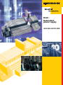
BL20 – Redundant power supply BL20-BR-24VDC-RED All brand and product names are trademarks or registered trade marks of the owner concerned. Edition 06/2013 © Hans Turck GmbH, Muelheim an der Ruhr All rights reserved, including those of the translation. No part of this manual may be reproduced in any form (printed, photocopy, microfilm or any other process) or processed, duplicated or distributed by means of electronic systems without written permission of Hans Turck GmbH & Co. KG, Muelheim an der Ruhr. Subject to alterations without notice Table of contents 1 About this manual 1.1 General .............................................................................................................................................................1-2 1.1.1 Additional documentation .................................................................................................................................................................1-2 1.2 Description of symbols used ..........................................................................................................................1-3 1.3 Overview .........................................................................................................................................................1-4 1.3.1 1.3.2 Prescribed use .........................................................................................................................................................................................1-4 Notes concerning planning /installation of this product ........................................................................................................1-4 2 Technical description 2.1 General function description..........................................................................................................................2-2 2.1.1 Usage of BL20-BR-24VDC-RED...........................................................................................................................................................2-2 2.2 Block diagram (single BL20-BR-24VDC-RED) ................................................................................................2-2 2.3 Technical data .................................................................................................................................................2-3 2.4 Wiring diagram ................................................................................................................................................2-4 2.5 LED description/ status display ......................................................................................................................2-5 2.6 Parameter data ................................................................................................................................................2-5 2.7 Diagnostic data of the module .......................................................................................................................2-5 2.8 Process data of the module ............................................................................................................................2-6 2.8.1 2.8.2 Process input data..................................................................................................................................................................................2-6 Process output/ control interface.....................................................................................................................................................2-7 3 Installation guidelines: BL20-BR-24VDC-RED 3.1 Redundant power supply of a BL20-station..................................................................................................3-2 3.1.1 3.1.2 3.1.3 3.1.4 Applicable gateways .............................................................................................................................................................................3-2 Redundant power feed directly next to the gateway ...............................................................................................................3-3 Redundant power supply of different potential groups..........................................................................................................3-5 Digital output modules in redundantly supplied stations......................................................................................................3-6 4 Configuring of redundantly supplied stations with the I/O-ASSISTANT Quick Start 4.1 Starting the TURCK I/O-ASSISTANT Quick Start............................................................................................4-2 4.2 Configuring the BL20-station in the Quick Start ..........................................................................................4-3 D301261 0613 - BL20-BR-24VDC-RED i ii D301261 0613 - BL20-BR-24VDC-RED 1 About this manual 1.1 General.............................................................................................................................................. 2 1.1.1 Additional documentation ...............................................................................................................................................................2 1.2 Description of symbols used ............................................................................................................ 3 1.3 Overview .......................................................................................................................................... 4 1.3.1 1.3.2 Prescribed use .......................................................................................................................................................................................4 Notes concerning planning /installation of this product ......................................................................................................4 D301261 0613 - BL20-BR-24VDC-RED 1-1 About this manual 1.1 General This manual describes the BL20 Bus Refreshing module for redundant power supply BL20-BR-24VDCRED. It contains the description of the technical features and functions as well as special installation guidelines. The BL20-BR-R24VDC-RED can currently only be used with some gateways, specified within chapter 3, Installation guidelines: BL20-BR-24VDC-RED (page 3-1). 1.1.1 Additional documentation D300717 "BL20 I/O modules - Hardware and Engineering" D300956 "BL20/BL67– USER MANUAL FOR PROFIBUS-DPV1" D301004 "BL20 – Gateway for Modbus TCP" 1-2 D301261 0613 - BL20-BR-24VDC-RED Description of symbols used 1.2 Description of symbols used Danger This sign can be found next to all notes that indicate a source of hazards. This can refer to danger to personnel or damage to the system (hardware and software) and to the facility. This sign means for the operator: work with extreme caution. Attention This sign can be found next to all notes that indicate a potential source of hazards. This can refer to possible danger to personnel and damages to the system (hardware and software) and to the facility. Note This sign can be found next to all general notes that supply important information about one or more operating steps. These specific notes are intended to make operation easier and avoid unnecessary work due to incorrect operation. D301261 0613 - BL20-BR-24VDC-RED 1-3 About this manual 1.3 Overview Attention Please read this section carefully. Safety aspects cannot be left to chance when dealing with electrical equipment. This manual includes all information necessary for the prescribed use of TURCK devices. It has been specially conceived for personnel with the necessary qualifications. 1.3.1 Prescribed use Appropriate transport, storage, deployment and mounting as well as careful operating and thorough maintenance guarantee the trouble-free and safe operation of these devices. Danger The devices described in this manual must be used only in applications prescribed in this manual or in the respective technical descriptions, and only with certified components and devices from third party manufacturers. 1.3.2 Notes concerning planning /installation of this product Danger All respective safety measures and accident protection guidelines must be considered carefully and without exception. 1-4 D301261 0613 - BL20-BR-24VDC-RED 2 Technical description 2.1 General function description ............................................................................................................ 2 2.1.1 Usage of BL20-BR-24VDC-RED.........................................................................................................................................................2 2.2 Block diagram (single BL20-BR-24VDC-RED).................................................................................... 2 2.3 Technical data .................................................................................................................................. 3 2.4 Wiring diagram ................................................................................................................................. 4 2.5 LED description/ status display......................................................................................................... 5 2.6 Parameter data ................................................................................................................................. 5 2.7 Diagnostic data of the module.......................................................................................................... 5 2.8 Process data of the module............................................................................................................... 6 2.8.1 Process input data ...............................................................................................................................................................................6 – PROFIBUS-DP .....................................................................................................................................................................................6 – Modbus TCP .......................................................................................................................................................................................7 Process output/ control interface ..................................................................................................................................................7 2.8.2 D301261 0613 - BL20-BR-24VDC-RED 2-1 Technical description 2.1 General function description The module BL20-BR-24VDC-RED allows the redundant power supply of the BL20-System by redundant feed-in of system voltage US and field voltage UL. 2.1.1 Usage of BL20-BR-24VDC-RED The usage of the redundant BL20-BR-24VDC-RED modules is only supported by some BL20-gateway types for some fieldbus protocols: PROFIBUS-DPV1 (usage and installation guidelines, see chapter 3) BL20-GW-DPV1 Modbus TCP (usage and installation guidelines, see chapter 3) BL20-GW-EN 2.2 Block diagram (single BL20-BR-24VDC-RED) Figure 2-1: Block diagram of one single BL20-BR24VDC-RED Module bus VSD 5 VDC Monitoring VS Galvanic isolation Logic VS 5 VDC Diagnostics VS Diagnostics ULD Power bus 24 VDC ULD 24 VDC 5 VDC Galvanic isolation Galvanic isolation Monitoring 24 VDC US 24 VDC Diagnostics US Diagnostics UL UL 24 VDC EMC-filter EMC-filter System supply US Field supply UL US - system voltage (identical to USYS at the gateway) UL - field voltage VS - module bus voltage ULD - redundant field voltage VSD - redundant module bus voltage 2-2 D301261 0613 - BL20-BR-24VDC-RED Technical data 2.3 Technical data Table 2-1: Technical data Designation BL20-BR-24VDC-RED General technical data System voltage US 24 V DC (18 to 30 V DC) Redundant module bus voltage VSD 5 V DC Module bus current IMB max. 500 mA Field voltage UL 24 V DC (18 to 30 V DC) Field current IL max. 5 A Power loss PV < 1,5 W Ambient conditions Operating temperature -25 °C to 60 °C Storing temperature -25 °C to 85 °C Relative humidity 95 % Isolation voltages UL to US 500 Vrms US to VSD no isolation ULto ULD Note For all other technical data, please refer to the BL20 manual for I/O-modules (D300717 "BL20 I/O modules - Hardware and Engineering"). D301261 0613 - BL20-BR-24VDC-RED 2-3 Technical description 2.4 Wiring diagram Figure 2-2: Pin assignment BL20-BR24VDC-RED 24 VDC System supply US + – 11 21 12 22 13 23 14 24 – + 24 VDC Field supply UL PE 2-4 D301261 0613 - BL20-BR-24VDC-RED LED description/ status display 2.5 LED description/ status display Table 2-2: LED-displays LED Display Meaning Remedy DIA Red Module bus communication failure Check if more than two adjoining electronics modules have been pulled. Check the power supply to the module bus. Off No error message or diagnosis – Green Redundant module bus voltage (5 VDC) present – Off Redundant module bus voltage (5 VDC) not present Check the connection to the system voltage supply. Green System voltage (5 VDC) present – Off System voltage (5 VDC) not present Check the connection to the system voltage supply. Green System voltage (24 VDC) present – Off System voltage (24 VDC) not present Check the connection to the system voltage supply. Green Field voltage (24 VDC) present – Off Field voltage (24 VDC) not present Check the connection to the field voltage supply. Green Redundant field voltage (24 V DC) present – Off Redundant field voltage (24 V DC) not present Check the connection to the field voltage supply. VSD VS US UL ULD 2.6 Parameter data The module has no parameter data. 2.7 Diagnostic data of the module The module has no diagnostic data, but it provides status information in the process input data (see Process input data (page 2-6)). D301261 0613 - BL20-BR-24VDC-RED 2-5 Technical description 2.8 2.8.1 Process data of the module Process input data The module provides 4 Bit of process input data, which contain the following status information: Table 2-3: Process input bits Bit 3 Bit 2 Bit 1 Bit 0 DIA ULD DIA VS DIA US DIA UL Table 2-4: Meaning of process input bits Designation Value Meaning DIA UL 0 UL is not within the permissible range 1 UL (24 V DC) is connected to the device 0 US is not within the permissible range 1 US (24 V DC) is connected to the device 0 VS is not within the permissible range 1 VS (5 V DC) for the module bus supply is delivered by the device 0 ULD is not within the permissible range 1 ULD (24 V DC) is connected to the device DIA US DIA VS DIA ULD PROFIBUS-DP In PROFIBUS-DP, 1 byte is reserved for the status messages of each BL20-BR-24VDC-RED, whereas only bits 0 to 3 are used as described above. 2-6 D301261 0613 - BL20-BR-24VDC-RED Process data of the module Modbus TCP In Modbus TCP, all process data of a station are mapped. The following example shows a mapping report of a BL20-station with 4 BL20-BR-24VDC-RED (two redundantly supplied potential groups, see also Figure 3-2: Station assembly with BL20-GW-EN and redundant power supply) generated using the software tool I/O-ASSISTANT (FDT/DTM). Figure 2-3: Modbus report, mapping of process input bits 2.8.2 Process output/ control interface The device has no process output data. D301261 0613 - BL20-BR-24VDC-RED 2-7 Technical description 2-8 D301261 0613 - BL20-BR-24VDC-RED 3 Installation guidelines: BL20-BR-24VDC-RED 3.1 Redundant power supply of a BL20-station ...................................................................................... 2 3.1.1 3.1.2 Applicable gateways...........................................................................................................................................................................2 Redundant power feed directly next to the gateway.............................................................................................................3 – Gateway supply ................................................................................................................................................................................3 – Base modules to be used next to the gateway .....................................................................................................................4 Redundant power supply of different potential groups........................................................................................................5 – Base modules to be used for redundant supply of potential groups ...........................................................................5 Digital output modules in redundantly supplied stations....................................................................................................6 3.1.3 3.1.4 D301261 0613 - BL20-BR-24VDC-RED 3-1 Installation guidelines: BL20-BR-24VDC-RED 3.1 Redundant power supply of a BL20-station The redundant power supply of a BL20-station is realized using two modules BL20-BR-24VDC-RED which are placed directly to the right of the gateway. It is also possible to insert two redundant power supply modules within a station in order to redundantly supply further potential groups if required. 3.1.1 Applicable gateways The BL20-BR-24VDC-RED for redundant power supply can be used with: BL20-GW-DPV1 BL20-GW-EN 3-2 D301261 0613 - BL20-BR-24VDC-RED Redundant power supply of a BL20-station 3.1.2 Redundant power feed directly next to the gateway Gateway supply The voltage feed-in of UL at the first BL20-BR-24VDC-RED next led through to the gateway. Electrical bridges at the gateway between UL and USYS as well as between GNDL and GNDSYS are used to supply the gateway electronics using UL connected to the first BL20-BR-24VDC-RED. Note Please observe the following: Usys (gateway) = US (BL20-BR-24VDC-RED) = system voltage Attention UL and USYS are not galvanically isolated in the first potential group with redundant BL20-BR24VDC-RED (see Figure 3-3: Redundant power supply of potential groups). Figure 3-1: Station assembly with BL20-GW-DPV1 and redundant power supply BL20-GW-DPV1 BL20-BR-24VDC-RED BL20-BR-24VDC-RED further modules BL20-BR-24VDC-RED BL20-BR-24VDC-RED further modules A B Slot 2.1 BL20-S4x-SBBC Slot 1.1 BL20-P4x-SBBC-G Potential group 1 Slot 2.2 BL20-S4x-SBBC Slot 1.2 BL20-P4x-SBBC-B Potential group 2 A bridge between UL/USYS and GNDL/GNDSYS to supply the gateway B slot x.y x = position y = potential group D301261 0613 - BL20-BR-24VDC-RED 3-3 Installation guidelines: BL20-BR-24VDC-RED Figure 3-2: Station assembly with BL20-GW-EN and redundant power supply BL20-BR-24VDC-RED BL20-BR-24VDC-RED further modules BL20-GW-EN BL20-BR-24VDC-RED BL20-BR-24VDC-RED further modules GW-EN GW IOs MS LNK ACT A B Slot 2.1 BL20-S4x-SBBC Slot 1.1 BL20-P4x-SBBC-G Potential group 1 Slot 2.2 BL20-S4x-SBBC Slot 1.2 BL20-P4x-SBBC-B Potential group 2 A bridge between UL/USYS and GNDL/GNDSYS to supply the gateway B slot x.y x = position y = potential group Base modules to be used next to the gateway For the first BL20-BR-24VDC-RED next to the gateway (slot 1), one of the following base modules has to be used: BL20-P4T-SBBC-G (tension clamp connection) BL20-P4S-SBBC-G (screw connection) For the second BL20-BR-24VDC-RED (slot 2) next to the gateway, one of the following base modules can be used: BL20-S4T-SBBC (tension clamp connection) BL20-S4S-SBBC (screw connection) 3-4 D301261 0613 - BL20-BR-24VDC-RED Redundant power supply of a BL20-station 3.1.3 Redundant power supply of different potential groups Base modules to be used for redundant supply of potential groups Figure 3-3: Redundant power supply of Gateway (e.g. BL20-GW-DPV1) potential groups BL20-BR-24VDC-RED BL20-BR-24VDC-RED further modules BL20-BR-24VDC-RED BL20-BR-24VDC-RED further modules Slot 2.1 BL20-S4x-SBBC Slot 1.1 BL20-P4x-SBBC-G 24 VDC 24 VDC Slot 2.2 BL20-S4x-SBBC Slot 1.2 BL20-P4x-SBBC-B A 24 VDC 24 VDC Potential group 1 Potential group 2 Aslot x.y x = position y = potential group For the first BL20-BR-24VDC-RED in a potential group (group n, slot 1), one of the following base modules has to be used: BL20-P4T-SBBC-B (Tension clamp connection) BL20-P4S-SBBC-B (Screw connection) For the second BL20-BR-24VDC-RED in a potential group (group n, slot 2), one of the following base modules can be used: BL20-S4T-SBBC (Tension clamp connection) BL20-S4S-SBBC (Screw connection) D301261 0613 - BL20-BR-24VDC-RED 3-5 Installation guidelines: BL20-BR-24VDC-RED 3.1.4 Digital output modules in redundantly supplied stations Attention UL and US (USYS) are not galvanically isolated in the first potential group with redundant BL20BR-24VDC-RED (see Figure 3-3: Redundant power supply of potential groups). In order to support safe disconnection of digital output signals, digital output modules should be placed within a redundantly supplied potential group with galvanic isolation of UL and US (USYS). An usage within the first potential group following the gateway is not reasonable. 3-6 D301261 0613 - BL20-BR-24VDC-RED 4 Configuring of redundantly supplied stations with the I/O-ASSISTANT Quick Start 4.1 Starting the TURCK I/O-ASSISTANT Quick Start ............................................................................... 2 4.2 Configuring the BL20-station in the Quick Start............................................................................... 3 D301261 0613 - BL20-BR-24VDC-RED 4-1 Configuring of redundantly supplied stations with the I/O-ASSISTANT Quick Start 4.1 Starting the TURCK I/O-ASSISTANT Quick Start 1 Open PACTware™ 2 Start the Quick Start using the "Project → TURCK I/O-ASSISTANT Quick Start"-command.^ Figure 4-1: Starting the Quick Start 4-2 D301261 0613 - BL20-BR-24VDC-RED Configuring the BL20-station in the Quick Start 4.2 Configuring the BL20-station in the Quick Start 1 Select the option "configure the system manually" and confirm the selection with "Next". Figure 4-2: Starting the Quick Start D301261 0613 - BL20-BR-24VDC-RED 4-3 Configuring of redundantly supplied stations with the I/O-ASSISTANT Quick Start 2 Select the fieldbus interface and the protection class and confirm the selection with "Finish". Note Please observe, that the redundant power supply is only possible with the gateways defined in chapter 3, page 3-2. Figure 4-3: Selecting Fieldbus interface and Protection class 4-4 D301261 0613 - BL20-BR-24VDC-RED Configuring the BL20-station in the Quick Start 3 The dialog box "COM1 Busaddress management" shows a selection of gateways for the chosen fieldbus protocol. 4 Select the gateway to be used and confirm with "ok". Figure 4-4: Selecting the gateway D301261 0613 - BL20-BR-24VDC-RED 4-5 Configuring of redundantly supplied stations with the I/O-ASSISTANT Quick Start 5 In the new window "Gateway Quick Start" activate the redundant power supply of the station by selecting the respective check box. 6 Select the used connection type and define the number and the type of the required I/O-channels. 7 If necessary select one of the provided base modules for the respective electronics module. Figure 4-5: Activating the redundancy and defining the number and type of required I/Ochannels 8 The station is automatically checked. 9 Confirm your station configuration with "Ok". 10 The station is automatically configured. 4-6 D301261 0613 - BL20-BR-24VDC-RED Configuring the BL20-station in the Quick Start 11 The needed supply modules are added and, wherever one Bus Refreshing module is configured, the second one for the redundant supply is set automatically as well. Figure 4-6: I/O-configuration with redundant Bus Refreshing modules D301261 0613 - BL20-BR-24VDC-RED 4-7 Configuring of redundantly supplied stations with the I/O-ASSISTANT Quick Start 4-8 D301261 0613 - BL20-BR-24VDC-RED Hans Turck GmbH & Co. KG 45472 Mülheim an der Ruhr Germany Witzlebenstraße 7 Tel. +49 (0) 208 4952-0 Fax +49 (0) 208 4952-264 E-Mail [email protected] Internet www.turck.com D301261 0613 www.turck.com