1
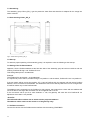
You will find the revision number of your CS121_SPI_II as button onto the device. The revision number 002 will
be delivered from september 2010 by default. The older revisions will be addressed on another way, please
take a look into chapter 8.5 for further information.
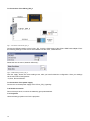
The CS121_SPI_II gateway is polling by itself accordingly, cyclical to the CS121. At a valid Modbus answer the
UPS data will be send with an additional byte and Modbus error byte to the Profibus cyclical.
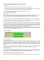
It is required to select into the module “64 words I/O (consistent) into the Profibus master out of the GSD file
UGIC3218”.
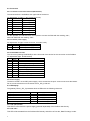
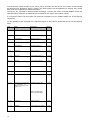
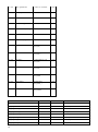
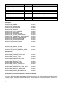
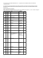
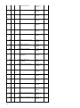
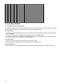
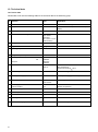
For the allocation of the UPS data to the transferred bytes on the Profibus, please take a look into the following
table.
Byte
Name
Description
Lenght
1
Counter
Increase at valid answer
1 Byte
2
Modbus Error Byte
Data valid if 0x00 only
1 Byte
3+4
OUTP0WER0
Outpower Phase 1 %
1 Word
5+6
OUTP0WER1
Outpower Phase 2 %
1 Word
7+8
OUTP0WER2
Outpower Phase 3 %
1 Word
9 + 10
BATTCAP
Battery Capacity %
1 Word
11 + 12
INVOLT0
Input Voltage Phase 1 V
1 Word
13 + 14
INVOLT1
Input Voltage Phase 2 V
1 Word
15 + 16
INVOLT2
Input Voltage Phase 3 V
1 Word
17 + 18
TEMPDEG
Temperature C°
1 Word
19 + 20
AUTONOMTIME
Autonomy Time minutes
1 Word
21 + 22
STATUS (e. g. UPS normal
= “4”, Powerfail = “12”,
Battery test running = “68”,
Bypass = “5” )
UPS Status (ASCII HEX)
1 Word
Please note UPSMAN
status bytes table below
23 + 24
BATTVOLT
Battery Voltage V
1 Word
25 + 26
INFREQ0
Input Frequency Hz Phase
1
1 Word
14