1
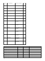
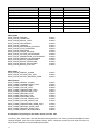
149 U
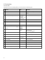
3/4 Sensormanager sensor 7
Analog value
1
150 U
3/4 Sensormanager sensor 8
Analog value
1
Example:
Request address 100 – 113 with module -> 16 words I/O (consistently)
0x01 0x04 0x00 0x64 0x00 0x12 0x00 0x00 0x00 0x00 0x00 0x00 0x00 0x00 0x00 0x00 0x00 0x00 0x00 0x00
0x00 0x00 0x00 0x00 0x00 0x00 0x00 0x00 0x00 0x00 0x00 0x00
The first 6 bytes contain the request, the other bytes will be filled up with 0x00. The checksum calculation will be
arranged from the CS121_SPI_II automatically and attached.
Byte 1 = Slave address, is always 1 at the CS121
Byte 2 = Modbus Function Code, the CS121 provides 0x03 or 0x04
Byte 3 = High byte of the start address, first measuring value, the CS121 starts with 0x64 (100 dez.)
Byte 4 = Low byte of the start address, first measuring value, the
CS121 starts 0x64 (100 dez.)
Byte 5 = High byte of the amount of the requested values, dependent of the used module of the GSD file
Byte 6 = Low byte of the amount of the requested values, dependent of the used module of the GSD file
Answer
0x01 0x04 0x12 0x00 0x63 0x00 0x58 0x00 0x4D 0x00 0x64 0x00 0xE6 0x00 0xE7 0x00 0xE8 0x00 0x17 0x00
0x0F 0x00 0x04 0x00 0xE9 0x00 0x32 0x00 0x00 0x00 0x00 0x00
Attention: Please note at the amount of the polling values, that the input buffer will not overflow at the answer!
Byte 1 = Slave address
Byte 2 = Modbus Function Code
Byte 3 = Amount of the following data words
Byte 4 = High byte of the first value of the CS121 (100 dez.)
Byte 5 = High byte of the first value of the CS121 (100 dez.)
Byte 6 = High byte of the second value of the CS121 (101 dez.)
Byte 7 = High byte of the second value of the CS121 (101 dez.)
etc.
It is required to define a loop into the Profibus master programming, that the content of the request will change.
E.g. request: Modbus address 100 – 113, request: Modbus address 114 – 126 or rather further, if more values
are essential.
9. Error Treatment
9.1 Error treatment by the CS121_SPI_II
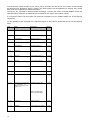
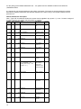
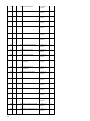
Detects the gateway an error, so it will be signalized via the LED state (red shining). Coincident the error
number will be displayed pursuant of the following table via the LEDs « Error No ».
You can distinguish two error categories :
Heavy errors (1-5) : It is required to reset the gateway. If the error will occur again, it is required to exchange it
and to send it for reparation.
Warnings (6-15) : These warnings will be displayed for one minute for your information only and will be reset
automatically, but if these warnings will occur frequently, please advise the customer service.
The flashing frequency is 0,5 Hertz at custom errors. The error will be displayed as long as the « Set Warning
Time » was defined.
The displays are not valid into configuration mode and for internal purpose only.
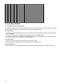
LED8 LED4 LED2 LED1 Error number/ID Error description
0
0
0
0
0
Reserved
0
0
0
1
1
Hardware error
0
0
1
0
2
EPROM error
21