1
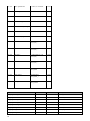
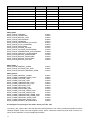
Table of Contents
1. Information of CE Marking of the Assembly Group
1.1 EU Directive EMV
1.2 Operating range
1.3 Assembling guideline
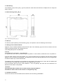
1.4 Mounting of the device
1.5 Operation at switch cabinets
2. Advices for the Manufacturer of Machines
2.1 Introduction
2.2 EU Directive Machines
3. Introduction
4. The Operating Modes of the Gateway
4.1 Data Exchange Mode
5. Functionality of the System
5.1 General explanation
5.2 Interfaces
5.3 Possible data lenghts
6. Hardware Connections, Switches and Diodes
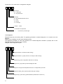
6.1 Device marking
6.2 Connectors
6.2.1 Connectors to the external device (RS-Interface)
6.2.2 Connector power supply
6.2.3 ProfibusDP connector
6.2.4 Power supply
6.3 LED display
6.3.1 LED “(Bus) Power“
6.3.2 LED “Bus“
6.3.3 LED “(Bus) State“
6.3.4 LED “Power“
6.3.5 LED “State“
6.3.6 LEDs 1 / 2 / 4 / 8 (Error No / Select ID)
6.4 Switches
6.4.1 Termination Rx 422 + Tx 422 (serial interface)
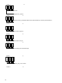
6.4.2 Coding switch S4 + S5 (serial interface)
6.4.3 Termination (Profibus)
6.4.4 Coding switch High + Low (Profibus-ID)
7. Start-Up guideline
7.1 Note
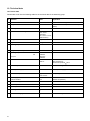
7.2 Components
7.3 Assembling
7.4 Scale drawing CS121_SPI_II
7.5 Start-up
7.6 Setting of the Profibus address
7.7 Profibus connection
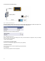
7.8 Connection of the CS121_SPI_II
7.9 Connection of the power supply
7.10 Shield connection
7.11 Projection
8. Protocol Modbus-RTU Master into the CS121_SP_II
8.1 Advices
8.2 CS121_SPI_II as Modbus-Master
8.2.1 Preparation
8.2.2 Data construction
8.2.3 Communication action
8.3 The lenghts byte
8.4 Example of the polling for the CS121 values Rev. 002
8.5 Example of the polling for the CS121 values prior Rev. 002
9. Error Treatment
9.1 Error treatment by the CS121_SPI_II
10. Assembling Guideline
10.1 Assembling of the assembly group
10.1.1 Assembling
3
5
5
5
5
5
5
5
5
5
5
6
6
6
6
6
6
6
6
7
7
7
7
7
7
7
7
8
8
8
8
8
8
8
8
9
9
9
9
11
11
11
11
11
12
12
12
12
13
13
13
13
13
13
13
13
17
21
21
22
22
22