1
United States Patent [191
_'[11]
[45]
Russell et al.
[54] TELEVISION IMAGE PROCESSING
Aug. 8, 1989
from any composite or component RGB video source
SYSTEM HAVING CAPTURE, MERGE AND
DISPLAY CAPABILITY
(26) may be fed into a signal processing circuit (60)
where they are digitized for processing in real time,
then reconverted to analog form and displayed on an
RGB analog television screen (22). During this process,
[76] Inventors: David P. Russell, 10 Swan PL,
Nissequogue, NY. 11780; Raymond
C. Papworth, 82 Wimpole Road,
Barton, Cambridge CB37AD,
users can capture a frame of the digitized video at ran
dom and store it in digitized format as a full size image
England
in the memory (32) of the graphics coprocessors (20). In
order to store live or full motion video (26) in the mem
[21] Appl. No.: 131,992
[22] Filed:
4,855,813
Patent Number:
Date of Patent:
ory (32), the memory read signal from the graphics
coprocessor is intercepted (84) in response to a grab
Dec. 11, 1987
[51]
[52]
Int. 01.4 ....................... .. H04N 9/74; H04N 5/45
U.S. c1. .................................... .. 358/22; 358/183;
c°ntr°l (54). and ‘1 memmy write Signal substituted
“lemme, Wlth the caPtured Video the" being written
358/903
written to the memory (32) from the video buffer (86)
[58]
Field of Search ........................ ., 358/22, 183, 903
_
‘
References Clted
,
through which it passes- Multiple variable Size Windows
may be created and overlayed in the composite display
(22), with each window being independent in size and
[56]
U.S. PATENT DOCUMENTS
content. The resultant composite television display (22)
3,875,329 4/1975 Nagel ............................ .. 358/903
358/22
4,357,624 11/1982 Greenberg ...... ..
.... .,
4,425,581
4,660,070
may have multiP1e “in frame images °verlayed over
full motion or live video together with graphics and/or
text. Separate color processing circuits (60a, 60b, 600)
358/183
4/1987
1/1984 Schweppe
Nishi et a1. et..................
al.
.. 358/22
are provided for parallel processing of the red, blue and
4,680,622
7/1987 Barnes et al. .
4,746,983
4/1988
green components of captured full color video to en
hance the color resolution, with a separate graphics
358/22
Hakamads ......................... .. 358/183
coprocessor (20a, 20b, 20c) and memory (32a, 32b, 320)
being in each circuit (60a, 60b, 60c).
Primary Examiner-John W. Shepperd
Attorney, Agent, or Firm-Bryan, Cave, McPheeters &
McRoberts
[57]
ABSTRACT
A television image processing system in which images
46 Claims, 10 Drawing Sheets
{'7 _____________ _—_l
I
r54
I
,
GRAB
1
HOST
COMPUTER J28 ]
C(WTROL
I” ------ -—5??
|
5/
|
amp/{KS
LIVE
TV
60- PROCESSOR
I
‘
L. _ _
L
1577977’!
- "*‘S/G/VAL
_
I
I
“7.4
_ _ _
k
|
32
W050 (we)
BUFFER
_ _ _ _ _
_ _
|
|
_
_
_
_
_
:
__._J
SIG/VAL 7
p/J'PMV rZZa
I
I
34
M96CONTROL
24
_ __ _ ~ _
l
\ M54400
iwwww
S/ GN/IL : SWITCH
I
,Pav
l COlI/T'ROL SIG; W556
82786081752) ‘
1
i
L30 M/TERCEPToR
i
726 l L20
l
PROCESS/Nc;
claw/r50.
US. Patent
Aug. 8, 1989
Sheet 2 of 10
I.
vwg.
4,855,813
US. Patent
Aug. 8, 1989
Sheet 5 0f 10
4,855,813
US. Patent
Aug. 8, 1989
Sheet 6 of 10
4,855,813
US. Patent
Aug. 8, 1989
M41290
8.5N28
3%
LLhQawugmkxs
EMSTlmQ
85Q3M%“
Sheet 10 of 10
4,855,813
1
4,855,813
2
coproessor controls the manipulation and retrievable
storage of instantaneously grabbed full motion video
TELEVISION IMAGE PROCESSING SYSTEM
HAVING CAPTURE, MERGE AND DISPLAY
images which are digitized and stored full size in a mem
CAPABILITY
ory for enabling selective merger of the images with the
graphics, text and full motion video in the composite
television display. In order to store the instantaneously
grabbed ful motion video, such as live video, the read
memory control signals from the graphics coprocessor
BACKGROUND OF THE INVENTION
1. Field of the Invention
The present invention relates to television image
are intercepted and write memory control signals are
processing systems and particularly to such systems
having frame capture, merge and display capability for
providing a user controllable composite video display
substituted therefor, thus, fooling the graphics co
processor such as the Intel 82786, into writing to mem
ory when it thinks it is reading. In order to enhance the
having a user selectable combination of full motion
color resolution of the captured and, ultimately, re
trieved still video images, when the full motion video
15 input, such as live video, is a full color signal, the input
2. Description of the Prior Art
Although there are prior art image processing sys
signal is decoded into its red, blue and green compo
video, still video images in user controllable variable
windows, graphics and/or text.
tems capable of capturing multiple video images and
nents and is digitally processed in parallel by individual
providing a composite display therefrom such as the
graphics coprocessors, and is recombined upon re
Magnavox Digital Stereo 4 Head VHS HQ VCR which
trieval to provide a high resolution color display,
enables the user to break the television screen into four 20 thereby providing the same range of color resolution as
?xed windows to enable a display of three still video
in the normal color television picture.
images and one live video image, there are none known
BRIEF DESCRIPTION OF THE DRAWINGS
to applicants which has the ?exibility of unlimited win
dows having user controllable variable size and location
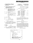
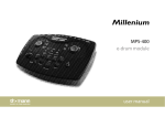
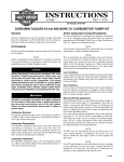
FIG. 1 is a functional block diagram of a prior art
in the composite with full size instantaneous image cap
ture and storage for providing user controllable merg
ing of still video images in these windows with graph
ics, text and/or live full motion video in an efficient and
economical system, particularly one capable of provid
ing high resolution color images. Image manipulation to
provide variable size window computer generated im
ages are well known, such as available by use of the
82786 graphics coprocessor available from Intel. How
25
con?guration for an Intel 82786 graphics coprocessor
for combining live video and graphics;
FIG. 2 is a functional block diagram, similar to FIG.
1, of a presently preferred embodiment of the present
30 invention illustrating a new utilization for an Intel 82786
graphics coprocessor in a configuration capable of in
stantaneous capture of live full motion video images;
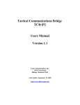
FIG. 3 is a functional block diagram, similar to FIG.
2, of a presently preferred embodiment of the image
ever, this coprocessor has never been used before with
live video images in a system to provide instantaneous 35 processing system of the present invention for provid
ing high resolution color image capture of live full mo
grabbing of these images at random under user control.
tion color video images;
This is so despite it having been known that the 82786
FIG. 4 is a functional block diagram illustrating the
graphic output can be combined with output from other
various bus interfaces between the image processing
video sources such as broadcast TV, video recorders,
circuit of the present invention and the host computer’s
and video laser disc players. Other prior art systems
data, address, and control buses;
lacking the full system ?exibility of the present inven
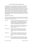
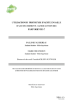
FIG. 5 is a more detailed functional block diagram of
tion are the Truevision line of microcomputer graphics
the embodiment of FIG. 2, illustrating a typical process
hardware and software available from AT&T, includ
ing circuit in the system of the present invention;
ing the VISTA and TARGA Videographics Adapters,
and the image capture board available from VuTech 45 FIG. 6 is a functional block diagram, partially, in
schematic, of the decoder circuit portion of the system
which is capable of overlaying a captured image in an
of FIG. 3;
EGA format over a moving image in a variable size and
FIG. 7 is a functional block diagram, partially in
location but with limited color resolution. Still another
schematic, of a typical analog to digital converter cir
prior art image processing system having limitation on
cuit for use with the system of FIGS. 3 and 5, illustrat
its ?exibility is disclosed in US. Pat. No. 4,700,181
ing processing of the red color component of the color
which is a graphics display system for creating compos
video signal;
‘
ite displays of stored image segments line by line in an
FIG. 8 is a functional block diagram, partially in
iterative process using slices to build up the composite
schematic, of a typical digital to analog converter cir
image. Thus, none of these prior art systems have the
desired efficiency and economics of the present inven 55 cuit for the red color component of the color video
tion.
DISCLOSURE OF THE INVENTION
The present invention relates to an image processing
system capable of selectively merging graphics, text,
digitized video frames and/or full motion video from
signal for use with the system of FIGS. 3 and 5;
FIG. 9 is a schematic diagram, partially in block, of
the video output circuit portion of the system of the
present invention;
FIG. 10 is a schematic diagram, partially in block, of
a reference voltage circuit for the system of the present
any composite or RGB component video source, such
invention;
FIG. 11 is a schematic diagram, partially in block, of
as live video, video camera, video laser disc or video
a power ?lter circuit for the system of the present in
cassette recorder, into a user selectable composite tele
vision display in which a number of windows may be 65 vention;
overlayed with the windows having variable size and
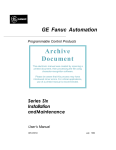
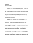
FIG. 12 is a functional block diagram of the video
location under user control. One of the windows or the
controller portion of the system of the presnnt inven
background may contain motion video. A graphics
tion.
3
4,855,813
FIG. 13 is a diagrammatic illustration of the line TV
signal source portion of the system of FIG. 2; and
FIG. 14 is a detailed functional block diagram similar
to FIG. 5, of the embodiment of FIG. 2, illustrating a
complete R, G, B processing circuit in the system of the
present invention.
BEST MODE FOR CARRYING OUT THE
INVENTION
4
signal in its red, blue and green components is em
ployed, with the retrieved parallel processed red, blue
and green components ultimately being recombined in
the video output circuit 40 (FIG. 9), although if desired
the components may be luminance and color difference
signals. For the sake of clarity, the same reference nu
meral is used throughout for the same functioning com
ponent.
The image processing system of the present invention
Referring now to the drawings in detail, and initially
may preferably be implemented as a single slot, AT
to FIG. 1, FIG. 1 illustrates a conventional prior art
con?guration for the Intel 82786 graphics coprocessor
compatible image processing board which provides free
flowing, real time digitalization of composite video and
20 employed as a video interface, such as described in
RGB analog video inputs, such as NTSC, PAL, SEA
Chapter 6 of the 1987 edition of the 82786 Graphics
Coprocessot User’s Manual, the contents of which is
CAM or other similar video formats. Real time full
motion or moving video pictures, such as via closed
hereby speci?cally incorporated by reference herein in
circuit TV or VCR/VTR outputs or live television
its entirety. As shown in FIG. 1, the graphics coproces
signals 26, can be displayed as real time full motion
sor 20 is connected to a CRT monitor or display 22
through a video switch 24 which also receives a live
video pictures and captured as independent still frames
or frozen video images, with a time base correction
television signal input 26 which may be combined with 20 circuit preferably being incorporated into the image
the graphic output from the graphics coprocessor 20,
processing system of the present invention in order to
such as described in section 6.8 of the above User’s
maintain high quality for the captured or grabbed real
Manual, as long as the graphics coprocessor 20 is locked
time full motion video images.
in synchronization with the live video source 26. As
As shown and preferred in FIGS. 5 and 14, three
further shown in FIG. 1, the graphics coprocessor 20 is 25 graphics coprocessors 20a, 20b, 200, such as preferably
normally under control of a conventional host com
puter 28, with the graphics coprocessor 20 normally
providing memory read control signals via control path
30 to the memory, such as a dynamic random access
three Intel 82786 graphics coprocessors, are utilized in
the image processing system of the present invention to
provide high resolution fast throughput of digitized
video images. Fast throughput is preferably delivered
memory or DRAM 32, associated with the graphics 30 by dedicating each of the three graphics coprocessors
coprocessor 20 with data bidirectionally passing be
20a, 20b, 200 to one of the three primary colors red,
tween the graphics coprocessor 20 and the DRAM 32
blue, green, thereby preferably providing parallel pro
via data path 34. As described in section 6.5 of the
cessing of video images. Of course, if a monochrome
above User’s Manual, combining multiple 827865 in a
video signal is involved, then only one graphics co
system can provide greater resolution of colors than a 35 processor 20 would be needed, such as the typical con
system having one 82786, such as the prior art system of
?guration illustrated in FIG. 2. Each of the three color
FIG. 1. In the above prior art system, there is no provi
processing circuits which each preferably contain an
sion for instantaneous grabbing of a full motion video
82786 graphics coprocessor 20a, 20b, 20c and a DRAM
signal such as the live video signal 26 so that still video
32a, 32b, 32c, preferably contain at least one megabyte
images in multiple windows having variable size and 40 of storage capacity in each DRAM 32a, 32b, 320. This
location cannot be provided from the live television
quantity of memory may be any desired size depending
signal 26, nor can such images therefore be overlayed
on the desired storage capacity such as, by way of ex
on the live video signal with or without the addition of
ample providing for the storage of up to three maximum
graphics and/or text in the composite video display 22.
Referring now to FIGS. 2-12, the presently preferred
system of the present invention for providing multiple,
virtually unlimited variable windows of still video im
ages, graphics and/or text along with full motion from
resolution images (668x480 pixels for example for an
45 NTSC system and 668x575 for a PAL system) in the
image processing system of the present invention. Of
course, the images may be reduced in size, for example,
from 668 X480 pixels for an NTSC system to 334x 240
any composite or RGB component video source, such
pixels, with a resultant increase in the number of images
as laser disks, still frame recorders, video cassette re 50 which can be stored.
corders, video cameras and live television signals 26,
such as illustrated in FIG. 13, will be described. The
system of the present invention will be described as one
for preferably providing high resolution color images in
The resolution of compute generated images can
preferably be modi?ed to emulate CGA, EGA, and
EGA+ graphics and colors if desired. Multiple win
which full motion color video images, such as live color
dows, such as up to 16 by way of example, can be de
?ned and displayed on-screen, each with a different
television signals 26, may be instantly grabbed using the
graphics coprocessor 20, which normally merely gener
windows may contain a full motion video image or
ates computer images on a television screen, at random
by the user, digitized and stored as a full size video
image, and manipulated to provide a variable size and
location window for each grabbed image in the com
posite video display 22a in which the grabbed images
captured image. As previously mentioned, one of the
windows can be displayed as overlays on a full screen
real time moving or full motion video image in the
composite display 22, and each window’s size and con
tents can be independent of others displayed. Prefera
bly, hardware windows allow horizontal and vertical
are merged with text and/or graphics and/or full mo
tion video, such as live television signals or television
scrolling of images and windows, and pixel zooming of
preferred in FIG. 3, and as will be described in greater
ity, such as, by way of example, at a speed of 2.5 million
pixels per second, a circle drawing capability, such as,
up to 64 times is preferably supported. Preferably, other
signals from any composite video source. Preferably, in 65 features of the image processing system of the present
order to enhance the color resolution as shown and
invention include a line and polygon drawing capabil
detail hereinafter, parallel processing of the color video
5
4,855,813
6
by way of example, at a speed of 2 million pixels per
second, a solid area shading capability, such as, by way
of example, at a speed of 3.75 million pixels per second,
a block transfer capability, such as, by way of example,
bus. Signal “BALE” (buffered address latch enable)
at a speed of 15 million bits per second, and a character
drawing capability, such as, by way of example, at a
address bus are latched into comparator 58, which com
pares the state of these four address bits to the state of
speed of 1200 characters per second. Due to the use of
three 82786 coprocessors 20a, 20b, 20c, a maximum
tor 58 performs this comparison to detect when a mem
palette of 16.7 million colors, is available for display. At
any given time the number of colors from this maximum
palette is determined by the number of pixels chosen.
The video input is preferably composite video and the
aforementioned time base correction circuit provides
from the host computer’s 28 control bus is used to en
able address latches 46 and 48. The remaining four
address bits (Addr 16-19) of the host computer’s 28
Switch 1-1, 2, 3, given reference numeral 72. Compara
10
are latched into comparator 78, which compares the
state of these address bits to the state of Switch L4, 5, 6,
7, 8, given reference numeral 76.
'
automatic sync correction for any composite video
input source for ensuring high quality capturing and
display of video images.
The image processing system of the present invention
preferably digitizes composite or component RGB
video input signals. Preferably the video images at digi
As previously stated, logic array 50 uses the signal
“MAD” as part of the logical inputs necessary to deter
mine the direction in which bidirectional data bus driv
ers 42 and 44 will enable data transfers. Logic array 56
uses the signal “MAD” as part of the logical inputs to
determine whether an interrupt must be sent to the host
computer 28 for the initialization of a l6-bit data trans
fer, for example, or to disable signal “I/O Channel
Ready,” which will force the host computer 28 into a
wait state during a data transfer and thereby provides
tized as bit mapped screens, and, thus, the content of the
video images, for example text, graphics or TV pic
tures, does not affect the image processing or the resolu
tion of processed images. As a result, the image process
ing system of the present invention is an ideal medium
for the digitalization, capturing, and display of video
images, images which can include, by way of example,
scanned documents, photographs, VCR outputs, VTR
outputs, still frame recorder outputs, closed circuit TV
outputs, live video, and any other composite video
outputs available. Preferably, there are four subsystems
which comprise the image processing system of the
present invention; namely, the bus interface, the color
processors, the video interface, and the video control
ler.
The bus interface, which is shown by way of example
in FIG. 4, provides the interface between the image
processing system of the present invention and the data,
ory access is being requested by the host computer 28.
Signal “MAD” is generated by comparator 58 and sent
to logic arrays 52 and 56. Similarly, address bits A3-9
25
enough time for the color processor circuits 60a, 60b,
60c to complete a data transfer.
Logic array 54 preferably has four functions. The
?rst function is the generation of signal “SFTRS”, a
software selectable reset signal which is used to reset
the graphics controllers or coprocessors 20a, 20b, 20c
contained in the color processor circuits 60a, 60b, 60c,
respectively. This software selectable reset is preferably
“OR’d” with the host computer’s 28 hardware “reset”
signal. The second function of logic array 54 is the
generation of signal “WDA” (write pulse), which is
applied to D to A converter (DAC) 762 which gener
ates the four control voltages used by the decoder cir
cuits 64a, 64b, 64c. Converter 62 receives its reference
address, and control buses of the host compute 28. The
bus interface circuit is preferably comprised of conven
voltage from regulator 66. The third function of logic
tional bidirectional data bus drivers 42, 44, address bus 40 array 54 is the enabling of the host computer 28 to rend
latches 46, 48, programmable logic arrays 50, 52, 54, 56
the “Field Indent” (FI) and “Double Line Frequency”
and various associated control circuits. The bidirec
(D2) signals generated by the image processing system
tional data bus drivers 42, 44 provides the interface
of the present invention. The fourth function of array 54
between the host computer’s 28 data bus and the data
is the generation of signal “GRAB” which is used to
bus of the image processing system of the present inven 45 enable the storage of a video frame.
tion. Driver 42 drives data bits 0-7 and driver 44 drives
As was previously mentioned with respect to FIGS.
data bits 8-15. The direction in which the drivers 42, 44
5 and 14, by preferably dedicating individual color
are enabled is preferably controlled by programmable
processing circuits 60a, 60b, 60c to each of the three
logic array 50 which interprets signals from the host
primary colors, red, blue and green, a high speed, high
computer’s 28 control bus to select the desired data bus
quality image processing system is established, with
direction.
each circuit 60a, 60b, 60c being dedicated to the pro
Programmable logic array 52 generates the four most
cessing of one of the three colors. A typical one of these
signi?cant bits of the addresses used by the color pro
color processing circuits, such as 60a by way of exam
cessor circuits 60a, 60b, 600. In addition, this circuit 52
ple, is shown in FIG. 5. As was previously mentioned
controls the type of access to be performed on the color 55 each of the processing circuits 60a, 60b, 60c preferably
processor circuits 60a. 60b, 60c; i.e., memory access or
contains a graphics coprocessor 20a, 20b, 20c, respec
I/O access. Select signals generated by this circuit 52
tively, such as preferably the Intel 82786 graphics co
also enable any combination of the color processor
processor. Digitized video images are sent to the graph
circuits 60a, 60b, 60c to perform read or write opera
ics coprocessors 20a, 20b, 20c over the image processing
tions.
system’s data bus. Bidirectional data bus drivers 80, 82
When the appropriate control signals have been gen
act as selectable buffers to link the image processing
erated by logic arrays 50 and 52, the data bus outputs of
system’s data bus lines to the color processor circuit’s
bus drivers 42 and 44 are enabled, thereby providing a
60a internal data bus. Logic array 84 is the control
path for the transfer of data between the image process
signal interceptor which, under control of the graphics
ing system’s color processor circuits 60a, 60b, 60c and 65 coprocessor 20a, enables/disables drivers 80 and 82
the host computer’s 28 data bus. Address latches 46 and
when apropriate. In addition, interceptor 84 preferably
48 provide the interface between the host computer’s 28
generates signals “WE” (write enable) and “BE” (bus
address bus and the image processing system’s address
enable) which are used to control the storage and re
7
4,855,813
trieval of data to and from the DRAM 32a, with each
8
buffers which can hold one-hundred and twenty-eight
pixels. The 82786 graphics coprocessor 20a starts to
read video data at the beginning of the horizontal blank
ing period and continues until the FIFO buffers are full,
which occurs before the end of horizontal blanking. At
color processing circuit 60a, 60b and 60¢ each prefera
bly containing its own DRAM 32a, 32b, 32c, respec
tively, such as a l Megabyte><8 bitv DRAM. Address
lines A0-A8 of the DRAM 32a are output by the graph
ics coprocessor 20a.
the start of the active line period, pixels are taken from
the FIFO buffers and transferred to the 1 Megabyte>< 8
The control signal interceptor 84 enables video frame
grabbing in the image processing system of the present
bit DRAM 320. When the FIFO buffers empty to a
predetermined level, another memory access burst
starts which continues until the FIFO buffers are full
again. This process continues until the end of the dis
invention. When the host computer 28 signals the grab
control 54 to accept the live video, for example, the
grab control enables both a live video buffer 86 (F162)
and the control signal interceptor 84. The live video
buffer 86 preferably receives video information the
played line.
Thus, the ?rst memory access, after the start of a line,
is to a memory location one-hundred and twenty-eight
entire time the image processing system is in operation,
but does nothing with it until the Grab Control 54 is 15 pixels onwards from the beginning of the memory map
active. When the Grab Control 54 is active, the live
of the line. This method is used in the “gra ” process by
video buffer 86 sends the video data to the memory 32a
preferably de?ning a special “grab” mode memory map
via the data bus (D0~D15). The control signal intercep
which consists of two tiles (vertical strips); the ?rst tile
tor 84, as previously mentioned, changes the RD or
consists of one-hundred and twenty-eight pixels from
read signal from the graphics coprocessor 20a to a WR
the right side of the picture, and the second is the re
or write signal and sends the write signal to the video
mainder of the picture starting with the left edge.
memory 320. The live video signal is then passed to the
Incoming video data is preferably buffed by an exter
video memory 320 through the enabled video buffer 86
nal FIFO buffer with the same depth as the Color Pro
and stored as a digitized full size video frame of instan
cessor circuits’s 60a internal FIFO buffers. Incoming
taneously grabbed video.
25 video data is therefore arranged such that at the begin
Video data outputs from the graphics coprocessor
ning of a line the external FIFO buffer is empty. As
20a (VDATO-7) are preferably applied to selectable
explained above, the internal FIFO buffer is full at this
buffer driver 88 which receives its enable signal from
time. During the “frame grab”, memory accesses are
the image processing system’s control bus. When en
overridden to be “write” accesses so that each memory
abled, driver 88 passes the video data through to first-in
access represents one word “taken” from the external
first-out (FIFO) buffers 90 and 92 or directly to the D to
FIFO and one word “put into” the internal FIFO
A converter 620. Since buffers 90 and 92 are preferably
buffer. Similarly, each pixel of video represents one '
8 bit FIFO buffers, the ?rst eight video data bits (VDO
byte “taken out of” the internal FIFO and one byte “put
7) are applied to buffer 90 and the second eight video
into” the external FIFO (from the real time moving
data bits (VDO-7) are applied to buffer 92. Although 35 video source). Since the Video Controller circuit ar
the color processor circuits’s 600 internal data bus con
ranges the data ?ow so that the internal FIFO buffer
does not over?ow or under?ow, it follows that the
tains sixteen data lines in the above example, the 82786
graphics coprocessor 20a outputs only eight video data
external FIFO buffer, which mirrors the internal FIFO
buffer, starts out empty when the internal FIFO buffer
and their alternating accesses is preferably employed. 40 is full, and therefore will not over?ow or under?ow
Signals “SIL” and “SIH” control the selection of buff
either.
ers 90 and 92 and are received from the image process
The internal FIFO buffer does not generally perform
ing system’s control bus. Preferably, in order to provide
any useful function during the “grab” process but the
a display of real time full motion or moving video pic
control of its operation ensures that the external FIFO
tures without any noticeable delays, the image process 45 buffer operates correctly. In order for the handshaking
ing system of the present invention enables the FIFO
between the external and internal FIFO buffers to work
buffers 90, 92 and the DRAM 32a to be directly by
correctly, delays within the image processing system’s
passed. However, by nevertheless preferably passing or
subsystems must be accounted for. If the external FIFO
cycling the real time full motion or moving video pic
buffer is the “fall through” type, then they cannot be
bits at a time. This is why dual FIFO buffers 90 and 92
ture through the image processing system of the present
invention, these pictures are enhanced and time base
50
completely emptied during the active line since several
data words will always be moving through them from
corrected, thereby improving the quality of the real
time moving video pictures.
input to output. Since the internal FIFO buffers are
completely ?lled at the end of each memory access
FIFO buffers 90 and 92 , when enabled via signal
burst, this would cause an under?ow condition. This
“OE” from the image processing system’s control bus, 55 can be avoided by de?ning a further tile of ?eld color at
transfer stored video data via the Color Processor’s 60a
the left edge of the picture. The time taken to “display”
internal data bus to either the 82786 graphics coproces
this tile is chosen to be greater than the “fall through”
sor 20a directly or to the l MegabyteXS bit DRAM
time of the external FIFO buffer. Thus the external
320. This completes the loop of video storage and re
FIFO buffer runs ahead of the internal FIFO buffers by
trieval within each of the Color Processor circuits 60a,
this time so that data is always available at the outputs
60b, 60c. In order to better understand the ?ow of video
of the external FIFO buffer when it is required. This
data within each of the Color Processor 60a, 60b, 600,
extra tile, however, leads to two further considerations.
the following operation shall be described below.
The ?rst consideration is that it would appear that
In normal operation, the 82786 graphics coprocessor
there is now a danger of the external FIFO buffer’s
20a reads data from memory 32a using an interleaved 65 overflowing, but this does not occur in practice because
“fast page mode” technique; data being read at approxi
mately twice the rate that it will be displayed. The data
is read in “bursts” and is buffered by internal FIFO
the internal FIFO buffers are never allowed to become
much less than half full, and therefore the external
FIFO buffer never gets much more than half full. The
9
4,855,813
10
video input to the image processing system is via con
total FIFO buffer depth is one-hundred and twenty
eight pixels and a “dummy tile” of a sixteen pixel width
is sufficient to overcome the “fall through” problem,
nector 98. When termination of this plug/input is re
quired, a jumper 100 can be inserted. The composite or
thereby establishing a large safety margin.
component RGB video input is applied directly from
The second consideration is what happens to the
right edge of the memory map if an extra tile is put in at
the left. The 82786 graphics coprocessor 20a continues
?lter circuit 102 and the Luminance Path Delay circuit
to read data for the de?ned memory map, even if the
chrominance component of the composite video signal.
memory map is larger than can actually be displayed;
until blanking time. Memory accesses are always at least
However, due to the delay inherent in the Chroma Pass
Filter circuit 102, a delay must also be added to the
connector 98 to two distinct circuits; the Chroma Pass
104. The Chroma Pass Filter circuit 102 selects the
sixty-four pixels ahead so the extra tile can be accom
Luminance path if proper synchronization is to be main
modated.
tained. The Luminance Path Delay circuit 104, com
When a frame is to be grabbed, the normal memory
prised of an inductor capacitor, and variable capacitor
accesses for reading video data are preferably overrid
preferably develops the required delay to synchronize
den to store video data instead. However, other types of 5 the chrominance and luminance paths.
memory accesses must also be considered in order to
Decoder 106 decodes the luminance and chromi
not cause any undesirable effects. The four types of
nance signals (from the composite or component RGB
normal memory accesses are RAM Refresh Cycles,
video input) to generate the red, green and blue compo
Host Accesses, Graphics Coprocessor Accesses, and
nents. Control voltages for brightness, contrast, color
20
Display Processor Control Accesses.
saturation and hue are provided from the bus interface
The RAM Refresh Cycles generated by the 82786
circuit’s D to A Converter 62. Jumper 108 is provided
graphics coprocessor 20a are “RAS only” cycles. In
to select between the composite or component RGB
order for the memory devices to recognize such cycles
video input from connector 98 or the Red, Green, Blue
it is only required that signal “CAS” be high; the state
(RGB) and Sync inputs from connector 98. Adding
of signal “WRITE” is unimportant so no undesirable 25 jumper 108 disables the composite video input and ena
effects will result. However insofar as Host Accesses
bles the RGB/ Sync inputs to be fed directly to decoder
and Graphics Coprocessor Accesses, they must not be
106. Jumpers 110, 112, 114 are used to terminate the
allowed to occur during a frame grab.
Red,
Green, and Blue signal lines, respectively. When
With respect to Display Processor Control Accesses,
ever a signal line (from connector 98) is not in use, and
a terminating jumper exists for such a signal line, such a
jumper shall preferably be installed to ensure the integ
these occur at the beginning of each frame and at the
end of each “strip? “Write Overrides” must not occur
during any of these accesses. The window descriptor is
rity of the selected input signal.
read immediately following signal “VSYNC” at the
Variable Capacitor 116 is preferably used to adjust
beginning of the ?rst ?eld. Signal “Override” is there
fore preferably not asserted until the ?rst line is dis 35 the sub-carrier oscillator frequency generated by Crys
tal 118. Field Effect Transistor (FET) 120 converts
Burst Gate signal “BG” to a voltage level acceptable to
decoder 106. In addition to the composite video signal
being applied to decoder 106, the Chroma Pass Filter
played to avoid interference. For an interlaced picture,
two “strips” are de?ned, one for the ?rst ?eld and one
for the second. The ?rst “strip” descriptor is read with
the window descriptor. The second “strip” descriptor
would preferably normally be read immediately after
the video data for the last line in the ?rst “strip.” It is
dif?cult to avoid overriding such a “read” so the
40
circuit 102, and the Luminance Path Delay circuit 104,
the composite video signal is applied to another decoder
122, which separates the synchronizing (Comp Sync)
signal from the composite video signal. Decoder 122
“strips” are preferably modi?ed slightly; an extra line
also generates a “Mute” signal which indicates whether
being added to the ?rst “strip” and a line being removed
from the second “strip.” The effect of this is that the 45 or not a- video input is connected. Variable Resistor 124
is preferably used to control the horizontal oscillator
?rst line “displayed” on the second ?eld is in fact the
frequency input to decoder 122 via a sample of decod
?rst “strip.” The second “strip” descriptor is then read
er’s 122 “Comp Sync” signal.
at the end of the ?rst line on the second ?eld. It is easy
There are preferably three identical Analog to Digi
to avoid overriding this “descriptor read” by denying
tal Converter (ADC) circuits 130a, 130b, 1300 used in
the override signal at the “Vsync” signal following the
the image processing system of the present invention,
?rst ?eld and not asserting it again until the second line
one for each color signal (red, green, blue). As all three
of the second ?eld. Thus, the ?rst line of the second
130a, 130b, 1300 are identical, the following description
?eld is preferably not grabbed. The ?rst line of the ?rst
of the Red analog signal conversion circuit 130a, by
?eld is also preferably not grabbed in order to maintain
symmetry. However, by increasing the number of lines 55 way of example shall apply to all three. Referring now
to FIG. 7, the Red analog signal (from th Decoder
circuit 64) is applied ?rst to Variable Resistor 132,
which is used to adjust the voltage offset of the Red
Referring now to FIGS. 6-11, the video interface
analog signal (herein referred to as the “analog signal”).
subsystem of the image processing system of the present
invention shall now be described. The Video Interface 60 The analog signal is then applied to Variable Resistor
134, which is used to adjust the voltage range of the
subsystem itself is comprised of six subsystems; the De
analog signal. The purpose of these adjustments is to
coder circuit (FIG. 6), the Analog to Digital Converter
preferably make each color generate equal grey scale
circuit (FIG. 7), preferably the Digital to Analog Con
values. Jumper 136 is used to connect the analog signal
verter circuit (FIG. 8), the Video Output circuit (FIG.
9), the Reference Voltage circuit (FIG. 10), and the 65 input to a tuned circuit 138. This tuned circuit 1338' re
jects subcarrier signals and introduces loss for frequen
Power Filter circuit (FIG. 11).
Referring initially to FIG. 6, the decoder circuit 64
cies above the video band, thereby minimizing distor
“displayed” during a “grab,” it would be possible to
grab these lines, if desired.
shall be described. The composite or component RGB
tion of the analog signal input.
.
11
4,855,813
The output of Variable Resistor 134 is applied to
Operational Amplifier 140, which maintains a low im
pedance drive for the ADC 142. The output of Opera
tional Ampli?er 140 is then applied to ADC 142. The
output of ADC 142 is an 8 bit representation of the
12
200 contains the circuitry for synchronizing the opera
tions of the image processing system and controlling the
mixing of real time moving or full motion video pictures
and captured/stored video pictures. The Video Con
troller 200 is preferably comprised of four subsystems;
the Oscillator circuit the Synchronizing Signal Genera
tion circuit, the Overlay Control circuit, and the Grab
analog signal, and is preferably output directly to the
image processing system’s internal data bus. Clock sig
nals generated internally by the image processing sys
Control circuit, all of which are illustrated in FIG. 12.
For purposes of clarity, these various subsystems shall
be described in separate paragraphs below.
With respect to the Oscillator circuit, inverting
Driver 202 generates the main oscillator frequency of,
by way of example, 25 MHz. This main oscillator fre
tem are used to clock ADC 142, and are received di
rectly from the image processing system’s internal con
trol bus. A Live Video Enable (LVEN) signal from the
image processing system’s control bus is used to enable
the direct transfer of real time moving or full motion
video pictures through the ADC 142 to the image pro
quency is applied to logic array 204 which generates '
cessing system’s data bus.
15 three clock signals; 12.5 MHz (CLK), 12.5 MHZ
Similarly there are preferably three identical Digital
(NCLK‘), and 5 MHz (CIN), by way of example.
to Analog Converter (DAC) circuits 62a, 62b, 62c in the
Array 204 generates these three clock signals by count
image processing system one for each color (red, green,
ing down from the main oscillator frequency received
blue). As all three are identical, the following descrip
from oscillator 202.
tion of the Red DAC circuit 62a by way of example, 20 In order to maintain a phase lock between the 12.5
shall apply to all three. Referring now to FIG. 8, DAC
MHz clock signals and the video input signals (Compos
144 preferably receives digital data corresponding to
ite Video or RGB), a logic array 206 monitors signal
the Red composite signal from the image processing
“MUTE” from the Video Interface/Decoder circuit
system’s data bus. This data is preferably clocked into
and signal “XTL” from the Bus Interface circuit. When
DAC 144 by a clock signal which is received from the 25 either of these two signals becomes active, array 206
image processing system’s control bus. A Voltage Ref
outputs signal “XTL” to Analog Muliplexer 208. Ana
erence (VREF) signal is also preferably received from
log Multiplexer 208 then adjusts the control voltage
the image processing system’s control bus and is applied
which is being output to Crystal 210, and, upon receiv
to DAC 144. The analog output of DAC 144 is prefera
ing a phase lock signal from Phase Detector 212, out
bly applied to Buffer Ampli?er 146, which provides for
puts a “Phase-Adjust” signal to Main Oscillator 202. In
the proper impedance and voltage level of the Red
this mode, the 12.5 MHz clock signals are phase locked
analog signal output. Variable Resistor 148, is used to
to Crystal 210’s output. When the “MUTE” and
adjust the voltage offset of the Red analog signal output
“XTL” signals are not active, the output of Crystal 210
(Comp Out). A test point 150 is preferably provided at
is ignored, and Analog Multiplexer 208 instead phase
the output of Buffer Ampli?er 146 for calibration rou
locks the Main Oscillator 202 to the phase lock signal
tines if desired. The Red, Green, and Blue analog uut
generated by Phase Detector 214, which receives its
puts from each of the three DAC circuits 62a, 62b, 620
composite sync signal from the Video Interface/De
are directly linked to the Video Output circuit.
coder circuit.
Referring now to FIG. 9, the video output circuit 40
With respect to the synchronizing signal generation
preferably receives the Red, Green, and Blue analog 40 circuit portion of the video controller 200, Phase Detec
output signals from the DAC circuits 62a, 62b, 62c and
tor 214 generates the synchronizing signals for the
applies them through impedance matching resistors 152,
image processing system. It is controlled by the 5 MHz
154, 156 to a conventional 9-way D-shell connector 158.
clock signal from array 204. Phase Detector 214 prefer
The Composite Sync signal from the Video Interface
ably compares the Composite Sync signal from the
Circuit is applied through low impedance driver transis 45 Video Interface/Decoder circuit with its own inter
tors 160 and 162 to connector 158. Pins 3, 4, and 5 of
nally generated line frequency. A voltage proportional
connector 158 represent Red, Green and Blue analog
to the phase difference between the Composite Sync
signal and the internal line frequency is preferably out
put by Phase Detector 214 to Analog Multiplexer 208.
In addition, Phase Detector 214 generates Composite
Sync, Horizontal Sync, Vertical Sync, Field Indent,
signals, respectively. Pin 7 represents signal “Composite
Sync.” Pins 1 and 2 are tied to the image processing
system’s chassis/signal ground.
The Reference Voltage circuit is shown in FIG. 10
and preferably contains Regulator 164, which gener
ates, by way of example, a 1.4 V DC reference voltage
from the image processing system’s +5 V DC line. A
test point 166 may be provided for calibration routines,
if desired.
The Power Filter Circuit is shown in FIG. 11 and
preferably consists of two areas; a +5 V DC ?lter cir
cuit 168 and a +120 V DC regulator circuit 170. The
+5 V DC filter circuit 168 preferably maintains a con
stant current for the + 5 V DC for the image processing
system. The +120 V DC regulator circuit 170 is com
prised of a Regulator which outputs a nominal voltage
50
and Burst Gate signals. Because Phase Detector 214
utilizes a nominal supply voltage of +6.2 V DC, by
way of example, the sync signals output are not at ac
ceptable voltage levels for the image processing system.
To compensate for this, Driver 216 receives Phase De
tector 214’s Sync outputs and drives them to + 5 V DC
logic levels. These Sync outputs are then applied
throughout the image processing system’s subsystems.
Preferably, to compensate for “Dead Time” coinci
dence, Resistor 218 provides a bias current which de
velops a slight offset from phase coincidence. To avoid
erroneous lock to equalizing pulses, Phase Detector 214
outputs a “No Sync” signal to Schmitt Trigger 220,
of, by way of example, +9.6 V DC. A test point 172
may be provided for calibration routines.
65 which then switches over and causes a shift in the Phase
Now referring to FIG. 12, the video controller 200
Lock signal sent to Analog Multiplexer 208. This
portion of the image processing system of the present
changed Phase Lock signal is then applied to Main
invention shall now be described. The Video Controller
Oscillator 202 by Analog Multiplexer 208.
4,855,813
13
Should output timing uncertainty occur, the 5 MHz
14
enables full color image processing to provide video
Composite Sync signal from array 204 is resynchro
displays of text and/or graphics and/or still frame video
and/or full motion video in a composite overlay display
nized to the 12.5 MHz clock signal input of 222. If the
set up or hold time of the Composite Sync input to array
222 is too small, then timing jitter may occur. If this
having multiple windows of still video images, graphics
or text along with full motion video from any composite
video source, such as live TV signals, laser disks, still
frame recorders, video cassette recorders and video
cameras. The frames of video to be grabbed may be
grabbed at random and enhanced in size and color and
inserted in variable size windows with each window
happens, signal “DG” will be output by array 222 to
array 204. This adjusts the divider 204 for the 5 MHz
- clock signal so that the relative phase of the 5 MHz and
12.5 MHz clock signals are adjusted by one cycle of the
25 MHz Main Oscillator 202 clock signal. The edges of
the 5 MHz and 12.5 MHz clock signals now become
being independent of the others.
separated by 40 nanoseconds, by way of example.
What is claimed:
With respect to the overlay control circuit portion of
1. An image processing system capable of selectively
the video controller 200, using the outputs from Phase
Detector 214, array 206 generates the horizontal and 15 merging graphics, text, digitized video frames and/or
full motion video into a user selectable composite televi
vertical synchronizing signals required by the 82786
sion display, said system comprising a composite or
graphics coprocessors of the Color Processor circuit
component RGB video input source means, said com
60a, 60b, 60c. Array 206 demultiplexes the Blue channel
posite or component RGB video input source means
sync signals to extract the window status signals. Array
206 then preferably uses the least signi?cant video data 20 comprising means for providing a full motion video
input; a graphics coprocessor means capable of control
bit (VTO) from the Blue Color Processor circuit 626 to
lably retrievably storing digitized video frames for pro
generate the overlay control signal (SVEN). The out
puts of arrays 206 and 222 are then output to the image
viding a user controllable variable window in an output
processing system’s subsystems.
composite television display picture; memory means
operatively connected to said graphics coprocessor
means for receiving memory control signals therefrom,
With respect to the grab control circuit, when a
frame Grab is to occur, array 222 generates the override
(OVR), the Shift-in High (SIH), and the Shift-in Low
(SIL) signals used in the Color Processor circuits 60a,
60b, 60c.
said memory means having a data input/output means
for inputting and outputting data therefrom and a con
trol signal input means for enabling control of reading
For purposes of completeness and in order to better
and writing from and to said memory means; control
understand Port Addressing utilized within the image
processing system of the present invention, the follow
ing system parameters are given by way of example
signal interception means operatively connected be
tween said graphics coprocessor means and said control
signal input means for controllably intercepting read
memory control signals generated from said graphics
below in TABLE 1.
TABLE 1
Offset
35 coprocessor means and substituting write memory con
trol signals therefor for providing said write memory
Addresses within the block are assigned as follows:
Write Function
Read Function
control signals to said memory means control signal
input means; grab control means operatively connected
0
l
Contrast
Saturation
Field Ident
Double line signal
to said control interceptor means for controllably caus
2
Brightness
Grab
3
Hue
ing said interception of said read memory control sig
4
Memory Page
5
Processor select
6
Soft reset
7
Crystal Lock
Locations 0 to 3 are written as 8 bit values.
Location 4 is as follows:
Bits 0 to 3 Top four address bits
bit 7
nals during grabbing of a user selected full motion video
signal input from said composite video input source
means, said grab control means selectively substantially
instantaneously grabbing said full motion video signal
45 input in response to said user selection of a full motion
video frame to be grabbed; video buffer means opera
tively connected to said data input/output means for
0 for memory address, 1 for register
Location 5 is as follows:
bitO
bitl
bit2
Select processor 0 (Red)
Select processor 1 (Green)
Select processor 2 (Blue)
controllably providing said grabbed user selected full
50
It is possible to write to one or more processors but only one
may be read at one time.
Location 6
To give a Soft reset write 1 then 0 to bit 7 of this location.
Location 7 bit 7
If 0 is written to hit 7 of this location then the video clock
will lock to the input video signal if one is present. If
there is no input video signal then the clock will be
controlled by the internal crystal.
If 1 is written the bit then the clock will be crystal-locked
whether a video signal is present or not. This is useful when
it is desired to have a stable display (which does not include
live video) and there is ‘an unstable video input, such as from
a rewinding VCR.
At location 0 bit 7 is read the odd/even field ident signal.
At location 1 bit 7 is read a double line frequency signal.
Reading location 3 causes a frame to be grabbed; no meaningfull
value is read.
By utilizing the system of the present invention, a
?exible image processing system is provided which
motion video frame signal input to said memory means
for retrievable storage of said grabbed user selected full
motion video frame signal input, said grab control
means further being operatively connected to said video
buffer means for controlling said instantaneous grab
55
bing of said user selected video frame signal input, said
memory means retrievably storing said grabbed user
selected video frame as a digitized video frame, said
graphics coprocessor means enabling user manipulation
of said stored grabbed user selected video frame for
providing a still video image in said user controllable
variable window in said output composite television
display; and video switch and merging means for selec
tively merging said stored grabbed digitized video
frames with said full motion video and/or graphics
65 and/or text in said user selectable composite television
display picture; whereby a ?exible user controllable
multimedia television image processing system is pro
vided.
15
4,855,813
2. An image processing system in accordance with
16
video signals thereof, said graphics coprocessor means
processing said red, blue and green component video
signals in parallel for retrievably storing said user se
lected grabbed digitized video frame in its red, blue and
green components, said video switch and merging
claim 1 wherein said memory means is capable of re
trievably storing a plurality of different user selected
grabbed digitized video frames.
3. An image processing system in accordance with
claim 2 wherein said memory means is capable of re
means recombining said retrieved stored digitized red,
trievably storing said plurality of different user selected
grabbed digitized video frames as full sized video
blue and green components of said stored digitized
video frame for providing a high resolution full color
video output still video image therefrom in said user
selectable variable window for said still video image in
frames.
4. An image processing system in accordance with
claim 8 wherein said user controllable variable window
is user controllable in both size and location in said
said output composite television display.
17. An image processing system in accordance with
claim 16 wherein said full-motion video input comprises
5. An image processing system in accordance with
a live video signal input.
claim 4 wherein said full-motion video input comprises 15 18. An image processing system in accordance with
a live video signal input.
claim 16 wherein said composite or component RGB
6. An image processing system in accordance with
video input source means comprises video storage
claim 3 wherein said full-motion video input comprises
means.
a live video signal input.
19. An image processing system in accordance with
7. An image processing system in accordance with
claim 18 wherein said video storage means comprises
output composite television display picture.
claim 2 wherein said graphics coprocessor means is
laser disc means.
capable of user manipulation of said plurality of differ
20. An image processing system in accordance with
ent stored video frames and said video switch and merg
ing means is capable of selectively merging a user se
lected plurality of said plurality of said stored grabbed
digitized video frames with said full motion video, and
/or graphics, and/or text in said user selectable compos~
ite television display for providing a user selectable
composite television display comprising a user select
able plurality of windows of still video images, graphics
and/or text and/or full motion video.
claim 18 wherein said video storage means comprises
25
video cassette recorder means.
21. An image processing system in accordance with
claim 16 wherein said composite or component RGB
video input source comprises video camera means.
22. An image processing system in accordance with
claim 16 wherein said memory means retrievably stores
said grabbed user selected video frame as a full size
claim 7 wherein said memory means is capable of re
digitized video frame.
23. An image processing system in accordance with
frames.
means.
9. An image processing system in accordance with
claim 7 wherein each of said plurality of window in said
claim 23 wherein said video storage means comprises
composite television display is independently variable
laser disc means.
8. An image processing system in accordance with
claim 1 wherein said composite or component RGB
trievably storing said plurality of different user selected
grabbed digitized video-frames as full sized video 35 video input source means comprises video storage
in size and content.
10. An image processing system in accordance with
claim 7 wherein said full-motion video input comprises
a live video signal input.
11. An image processing system in accordance with
24. An image processing system in accordance with
25. An image processing system in accordance with
claim 23 wherein said video storage means comprises
video cassette recorder means.
26. An image processing system in accordance claim
1 wherein said composite or component RGB video
claim 7 wherein said composite or component RGB 45 input source comprises video camera means.
27. An image processing system in accordance with
video input source means comprises video storage
claim 1 wherein said video switch and merging means
means.
12. An image processing system in accordance with
claim 11 wherein said video storage means comprises
laser disc means.
13. An image processing system in accordance with
claim 11 wherein said video storage means cmprises
video cassette recorder means.
comprises host computer means-operatively connected
to said graphics coprocessor means and said grab con
50 trol means for controlling the operation thereof in re
sponse to said user selection.
28. An image processing system in accordance with
claim 27 further comprising color decoder means dis
posed between said full motion video composite video
14. An image processing system in accordance with
claim 7 wherein said composite or component video 55 input source means and said graphics coprocessor
means for decoding said full motion video input into
input source comprises video camera means.
15. An image processing system in accordance with
red, blue and green component video signals thereof,
claim 7 wherein said video switch and merging means
said graphics coprocessor means processing said red,
comprises host computer means operatively connected
blue and green component video signals in parallel for
to said graphics coprocessor means and said grab con 60 retrievably storing said user selected grabbed digitized
trol means for controlling the operation thereof in re
video frame in its red, blue and green components, said
sponse to said user selection.
video switch and merging means recombining said re
16. An image processing system in accordance with
trieved stored digitized red, blue and green components
claim 15 further comprising color decoder means dis
of said stored digitized video frame for providing a high
posed between said full motion video composite or 65 resolution full color video output still video image
component RGB video input source means and said
therefrom in said user selectable variable window for
graphics coprocessor means for decoding said full mo
said still video image in said output composite television
tion video input into red, blue and green component
display.
17
'
4,855,813
29. An image processing system in accordance with
claim 28 wherein said full-motion video input comprises
a live video signal input.
30. An image processing system in accordance with
claim 28 wherein said composite or component RGB
video input source means comprises video storage
18
36. An image processing system in accordance with
claim 34 wherein said composite or component RGB
video input source means comprises video storage
means.
37. An image processing system in accordance with
claim 36 wherein said video storage means comprises
laser disc means.
means.
38. An image processing system in accordance with
31. An image processing system in accordance with
claim 36 wherein said video storage means comprises
claim 30 wherein said video storage means comprises 10
video cassette recorder means.
laser disc means.
39. An image processing system in accordance with
32. An image processing system in accordance with
claim 30 wherein said video storage means comprises
claim 34 wherein said composite or component RGB
video input source comprises video camera means.
video cassette recorder means.
40. An image processin system in accordance with
33. An image processing system in accordance with
claim 28 wherein said composite or component RGB
claim 1 wherein said user controllable variable window
is user controllable in both size and location in said
video input source comprises video camera means.
output composite television display picture.
34. An image processing system in accordance with
41. An image processing system in accordance with
claim 1 further comprising color decoder means dis
posed between said full motion video composite video
input source means and said graphics coprocessor
means for decoding said full motion video input into
claim 1 wherein said memory means retrievably stores
said grabbed user selected video frame as a full size
digitized video frame.
42. An image processing system in accordance with
claim 41 wherein said user controllable variable win
dow is user controllable in both size and location in said
red, blue and green component video signals thereof,
said graphics coprocessor means processing said red,
blue and green component video signals in parallel for
retrievably storing said user selected grabbed digitized
output composite television display picture.
43. An image processing system in accordance with
claim 47 wherein said full-motion video input comprises
a live video signal input.
44. An image processing system in accordance with
trieved stored digitized red, blue and green components 30 claim 41 wherein said full-motion video input comprises
of said stored digitized video frame for providing a high
a live video signal input.
resolution full color video output still video image
45. An image processing system in accordance with
therefrom in said user selectable variable window for
claim 40 wherein said full-motion video input comprises
said still video image in said output composite television
a live video signal input.
display.
35
46. An image processing system in accordance with
35. An image processing system in accordance with
claim 1 wherein said full-motion video input comprises
claim 34 wherein said full-motion video input comprises
a live video signal input.
*
it
1C
*
*
a live video signal input.
video frame in its red, blue and green components, said
video switch and merging means recombining said re
45
50
55
65