1
UM0921
User manual
STM32-based LCD controller for TFT-LCDs
Introduction
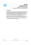
This user manual describes the hardware details for the STEVAL-CCM002V1
demonstration board "STM32-based LCD controller for TFT-LCDs" and the STM32-based
demonstration firmware. The system demonstrates the capabilities of the high-performance
flexible static memory interface (FSMC) of the STM32 for driving a TFT-LCD. The 3.5"
QVGA resolution TFT-LCD panel is interfaced with STM32 FSMC peripheral. The board is
designed to be interfaced as a daughterboard for the STM3210E-EVAL demonstration kit.
To summarize, the key features of the system are:
■
Displays images on the TFT-LCD using the STM32 as the LCD controller
– Banner display of images to show animation
– Slideshow of images to demonstrate static display model
■
STM32 FSMC drives the TFT using external SRAM as refresh RAM
■
Double-buffer allocation in refresh SRAM allows updating the source of dynamic images
■
On-board constant current drive circuit for the LEDs of the TFT-LCD backlight
■
Dimming control for the LEDs of the TFT-LCD backlight
■
Jumper headers offering freedom for easy analysis of the TFT-LCD interface to the
microcontroller
Figure 1.
September 2010
STM32-based LCD controller for TFT-LCD
Doc ID 17247 Rev 1
1/19
www.st.com
Contents
UM0921
Contents
1
Getting started . . . . . . . . . . . . . . . . . . . . . . . . . . . . . . . . . . . . . . . . . . . . . . 4
1.1
Package . . . . . . . . . . . . . . . . . . . . . . . . . . . . . . . . . . . . . . . . . . . . . . . . . . . 4
1.2
Hardware installation . . . . . . . . . . . . . . . . . . . . . . . . . . . . . . . . . . . . . . . . . 4
1.3
Hardware setup for MB672 Rev. B . . . . . . . . . . . . . . . . . . . . . . . . . . . . . . . 5
1.4
Demonstration images . . . . . . . . . . . . . . . . . . . . . . . . . . . . . . . . . . . . . . . . 5
1.5
Software installation . . . . . . . . . . . . . . . . . . . . . . . . . . . . . . . . . . . . . . . . . . 5
2
Hardware layout . . . . . . . . . . . . . . . . . . . . . . . . . . . . . . . . . . . . . . . . . . . . . 6
3
Hardware details . . . . . . . . . . . . . . . . . . . . . . . . . . . . . . . . . . . . . . . . . . . . 8
4
3.1
Connectors J1 ,J3 . . . . . . . . . . . . . . . . . . . . . . . . . . . . . . . . . . . . . . . . . . . 8
3.2
Jumper headers J2,J4 . . . . . . . . . . . . . . . . . . . . . . . . . . . . . . . . . . . . . . . . 8
3.3
Connector J5 . . . . . . . . . . . . . . . . . . . . . . . . . . . . . . . . . . . . . . . . . . . . . . . 8
3.4
Jumper header J6 . . . . . . . . . . . . . . . . . . . . . . . . . . . . . . . . . . . . . . . . . . . 8
3.5
Single-channel Schmitt inverter U1 . . . . . . . . . . . . . . . . . . . . . . . . . . . . . . 8
3.6
LED backlight controller U2 . . . . . . . . . . . . . . . . . . . . . . . . . . . . . . . . . . . . 8
3.7
Touchscreen controller U3 . . . . . . . . . . . . . . . . . . . . . . . . . . . . . . . . . . . . . 9
3.8
Low-drop power Schottky rectifier D1 . . . . . . . . . . . . . . . . . . . . . . . . . . . . 9
3.9
TFT-LCD . . . . . . . . . . . . . . . . . . . . . . . . . . . . . . . . . . . . . . . . . . . . . . . . . . . 9
Running the demonstration . . . . . . . . . . . . . . . . . . . . . . . . . . . . . . . . . . 10
4.1
STM32 banner display . . . . . . . . . . . . . . . . . . . . . . . . . . . . . . . . . . . . . . . 10
4.2
STM32 slideshow display . . . . . . . . . . . . . . . . . . . . . . . . . . . . . . . . . . . . . 10
4.3
TFT-LCD backlight dimming control . . . . . . . . . . . . . . . . . . . . . . . . . . . . . 10
5
Troubleshooting . . . . . . . . . . . . . . . . . . . . . . . . . . . . . . . . . . . . . . . . . . . 11
6
Revision history . . . . . . . . . . . . . . . . . . . . . . . . . . . . . . . . . . . . . . . . . . . 18
2/19
Doc ID 17247 Rev 1
UM0921
List of figures
List of figures
Figure 1.
Figure 2.
Figure 3.
Figure 4.
Figure 5.
Figure 6.
Figure 7.
Figure 8.
Figure 9.
STM32-based LCD controller for TFT-LCD . . . . . . . . . . . . . . . . . . . . . . . . . . . . . . . . . . . . . 1
STEVAL-CCM002V1 demonstration board mounted on MB672 STM3210E-EVAL
demonstration board . . . . . . . . . . . . . . . . . . . . . . . . . . . . . . . . . . . . . . . . . . . . . . . . . . . . . . . 4
Hardware layout: top view . . . . . . . . . . . . . . . . . . . . . . . . . . . . . . . . . . . . . . . . . . . . . . . . . . 6
Hardware layout: bottom view . . . . . . . . . . . . . . . . . . . . . . . . . . . . . . . . . . . . . . . . . . . . . . . 7
STM32 display mode switching . . . . . . . . . . . . . . . . . . . . . . . . . . . . . . . . . . . . . . . . . . . . . 10
STM32 demonstration board connector section for TFT-LCD . . . . . . . . . . . . . . . . . . . . . . 12
TFT-LCD 54-pin connector . . . . . . . . . . . . . . . . . . . . . . . . . . . . . . . . . . . . . . . . . . . . . . . . . 13
Single-channel inverter and LCD backlight driver. . . . . . . . . . . . . . . . . . . . . . . . . . . . . . . . 14
Touchscreen controller . . . . . . . . . . . . . . . . . . . . . . . . . . . . . . . . . . . . . . . . . . . . . . . . . . . . 15
Doc ID 17247 Rev 1
3/19
Getting started
UM0921
1
Getting started
1.1
Package
The demonstration kit package includes the following items:
●
Hardware content
–
●
–
●
1.2
STEVAL-CCM002V1 demonstration board
Software content
STEVAL_CCM002V1.hex file
Documentation
–
User manual (this document)
–
Application note AN3241 from www.st.com
–
Presentation
–
Schematics
–
BOM
Hardware installation
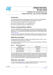
The STEVAL-CCM002V1 demonstration board is the daughterboard for the MB672
STM3210E-EVAL demonstration board.
For the board demonstration setup, follow the steps below:
1.
Connect STEVAL-CCM002V1 board connectors J3 and J1 to CN10 and CN11
respectively of the MB672 STM3210E-EVAL demonstration board
2.
Power on the MB672 STM3210E-EVAL demonstration board
Figure 2.
4/19
STEVAL-CCM002V1 demonstration board mounted on MB672 STM3210EEVAL demonstration board
Doc ID 17247 Rev 1
UM0921
1.3
Getting started
Hardware setup for MB672 Rev. B
Rev. B of the MB672 STM3210E-EVAL demonstration board is the release of an older
version. Rev. B differs from rev. D in terms of the placement of three signals: PD14, PD15
and PE1 on connectors CN10 and CN11 of the STM32E-Eval kit. Hence, certain changes
are required in the hardware to run the demonstration on the rev. B kit. The demonstration
firmware can be run on rev. B, mapping signals to the appropriate pin numbers as follows:
●
●
Signal connection changes on the STM32-E EVAL MB672 rev. B kit:
–
Connect pin 9 and pin 11 of CN11 to pin 31 and 32 of CN11, respectively
–
Connect pin 48 of CN10 to pin 24 of CN10
Signal connection changes on the STEVAL-CCM002V1demonstration board:
–
●
1.4
Pin PE1 on CN10 connects to 3.3 V when STEVAL-CCM002V1 is mounted on
STM32-E EVAL rev. B. Disconnect the track of pin 48 of J3 from 3.3 V
After successully mapping the signals, follow the steps below to run the demonstration:
–
Connect STEVAL-CCM002V1 board connectors J1 and J3 to CN10 and CN11
respectively of the MB672 STM3210E-EVAL demonstration board
–
Power on the MB672 STM3210E-EVAL demonstration board
Demonstration images
The demonstration makes use of static images present in NOR memory of the MB672
STM3210E- EVAL demonstration board. The images are copied by the firmware from NOR
memory to on-board external SRAM during firmware initialization. Then, the image files are
refreshed on the TFT-LCD by the microcontroller from the external SRAM only.
These images are programmed by default in NOR memory of the MB672 STM3210E- EVAL
demonstration board. If the images are not available in NOR memory, they can be easily
programmed in NOR memory using the USB DFU firmware.
The STM3210E-EVAL_NORFlash.dfu file for images is available in the firmware package
with AN3241 on www.st.com.
For more details about the board and NOR programming, refer to user manual UM0549 on
www.st.com. The USB DFU firmware is available for download from the STMicroelectronics
website: www.st.com.
1.5
Software installation
For firmware package installation and operation, refer to the firmware associated with
AN3241 on www.st.com.
Doc ID 17247 Rev 1
5/19
Hardware layout
2
UM0921
Hardware layout
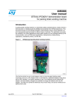
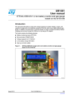
The demonstration kit hardware is designed with on-board jumper headers to offer easy
signal analysis for TFT-LCD interfacing to the STM32.
Figure 3.
6/19
Hardware layout: top view
Doc ID 17247 Rev 1
UM0921
Hardware layout
Figure 4.
Hardware layout: bottom view
Doc ID 17247 Rev 1
7/19
Hardware details
3
Hardware details
3.1
Connectors J1 ,J3
UM0921
J1, J3 (70PS, 2.54 mm dual-row female sockets) are mounted on the board to interface the
STEVAL-CCM002V1 demonstration board as a daughterboard to the MB672 STM3210EEVAL demonstration board.
3.2
Jumper headers J2,J4
J2, J4 (70PS, 2.54 mm dual-row male headers) can be mounted on the board and are
offered to allow easy analysis of TFT-LCD interfacing signals.
3.3
Connector J5
J5 FPC-GS200-XX1GX-XA (54PS, FPC connector 0.5 mm ZIF, side-entry SMT) is mounted
to connect the TFT-LCD glass to the STEVAL-CCM002V1 demonstration board.
3.4
Jumper header J6
J6 (10PS, 2.54 mm single-row male header) is the signal analysis connector for the major
TFT-LCD signals - touch signals, synchronization signals, backlight signals.
If the TFT-LCD signals are to be connected from sources other than the STM32 FSMC
signals, then R3, R4 can be demounted and J6 can be mounted to analyze the TFT-LCD
signals.
3.5
Single-channel Schmitt inverter U1
U1 74V1G14CTR (SOT223-5L) is a single Schmitt inverter.
U1 is mounted on-board to invert the microcontroller FSMC write-enable output signal. The
inverted FSMC write-enable signal acts as a pixel clock for the TFT-LCD panel.
3.6
LED backlight controller U2
U2 STLD40DPUR (QFN8) is the white LED power supply for the large display backlight. It is
capable of driving up to 10 white LEDs in series with maximum output of 20 mA and 37 V.
U2 is mounted to drive 6 white LED backlights of the on-board TFT-LCD with output current
of 20 mA and voltage 19.2 V.
PB6 of STM32F103ZET6 is interfaced to enable the input of U2. A 1 KHz PWM signal
output on PB6 from STM3210E is used as the enable input for U2. The TFT-LCD backlight
dimming control is implemented on the board by varying the duty cycle of the enable PWM
signal.
On-board potentiometer RV1 on the MB672 STM3210E-EVAL demonstration board is used
to demonstrate dimming control. Potentiometer RV1 is interfaced to MCU STM3210E of the
8/19
Doc ID 17247 Rev 1
UM0921
Hardware details
MB672 STM3210E-EVAL demonstration board using an ADC channel. Rotate the
potentiometer RV1 for TFT-LCD dimming control.
For more details about potentiometer hardware interface, refer to the user manual offered
with the MB672 STM3210E-EVAL demonstration board.
Note:
STLD40DPUR is offered with the IC surface acting as PGND (power ground). Make sure to
connect PGND to the ground terminal of the board.
3.7
Touchscreen controller U3
U3 STMPE811QTR (QFN16) is a 4-wire resistive touchscreen controller with a 12-bit ADC
for accurate, single-point touch detection. It converts touch on the touchscreen to digital
touch coordinates.
U3 is interfaced with four touch-sensing lines (TSC_X1, TSC_X2, TSC_Y1, and TSC_Y2) of
the TFT-LCD. The STMPE811 supports SPI and I2C interfacing. Here, the STMPE811 is
interfaced to the microcontroller of the MB672 STM3210E-EVAL demonstration board using
I2C2 interface.
U3 is not mounted on-board in the present solution .It can be easily mounted to support
touch detection.
3.8
Low-drop power Schottky rectifier D1
D1 STPS1L30A (SMA, VRRM = 30 V, IF = 1 A,VF = 0.3 V) is used for reverse-recovery
control in the U2 backlight control circuit.
3.9
TFT-LCD
TFT-LCD CT05350DW0000T is a transmissive TFT (thin film transistor) active matrix color
liquid crystal display (LCD) comprising an amorphous silicon TFT attached to each signal
electrode. The model consists of a TFT-LCD module, a driver circuit, backlight unit and
4-wire touch panel.
The resolution of the 3.5" TFT-LCD contains 320 × 240 pixels and can display up to 16.7 M
colors.
Doc ID 17247 Rev 1
9/19
Running the demonstration
4
UM0921
Running the demonstration
The STEVAL-CCM002V1 demonstration board is the interface board for the TFT-LCD. The
microcontroller for driving the TFT-LCD is available on the MB672 STM3210E-EVAL
demonstration board. Hence, the STEVAL-CCM002V1 demonstration board is mounted as
the daughterboard to the MB672 STM3210E-EVAL demonstration board. The board
supports two modes of display:
4.1
●
STM32 banner display
●
STM32 slide-show display
STM32 banner display
Upon successful power-up of the board, animation starts to play. In this mode, multiple
images display one after the other, enlivening the presentation.
Press key B3 to switch to slideshow mode.
4.2
STM32 slideshow display
Upon successful power-up of the board, two static images are displayed on the TFT-LCD as
in a slideshow.
Figure 5.
4.3
STM32 display mode switching
TFT-LCD backlight dimming control
The MB672 STM3210E-EVAL demonstration board potentiometer RV1 can be used to
control the dimming of the TFT-LCD backlight.
10/19
Doc ID 17247 Rev 1
UM0921
5
Troubleshooting
Troubleshooting
TFT-LCD display is black upon power-on
●
Reason: STM32-E demonstration kit on-board potentiometer RV1 is on zero
●
Solution: rotate the potentiometer RV1 to see the display
TFT-LCD display is white upon power-on, but no images are displayed
●
Reason: no images in the STM32E demonstration kit on-board NOR memory
●
Solution: refer to Section 1.4 for details
TFT-LCD image inversion
●
Reason : STEVAL-CCM002V1 ESD issues on the analysis jumpers J2, J4
●
Solution: avoid bare contact of hands or metallic components on analysis jumpers J2,
J4 and restart the kit
Doc ID 17247 Rev 1
11/19
Troubleshooting
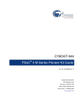
Figure 6.
UM0921
STM32 demonstration board connector section for TFT-LCD
-
*1'
3*
3*
3*
3&
5(6(7
3'
3'B/&'B5
3'B/&'B5
'9
3%
3%B 76&B6'$
3(B/&'B5
3(B/&'B*
3(B/ &'B*
3'B/&'B%
3(B/&'B*
3(B/&'B%
3*
*1'
3)
3)
3%
3%
9
3%
3&
3$
3$B63,B&6
*1'
3$
3&B76&B,17
3&B/&'B5(6(7
3)
9
$/
-
3*
3*
3*
3*
*1'
3'
3'
3'B/&'B5
3%
3%
3%
3%B76&B6&/
3(B/&'B5
3(B/&'B*
*1'
3'B/&'B%
3(B/&'B*
3(B/&'B*
*1'
3*
3*
3*
3&
5(6(7
3'
3'B/&'B5
3'B/&'B5
'9
3%
3%B 76&B6'$
3(B/&'B5
3(B/&'B*
3(B/ &'B*
3'B/&'B%
3(B/&'B*
3(B/&'B%
3*
*1'
3)
3)
3%
3%
3*
3)
3)
3)
*1'
3&
3$B63,B'$7$
3$B63,B&/.
3$
3$
3%
3&
3$
3$B63,B&6
*1'
3$
3&B76&B,17
3&B/&'B5(6(7
3)
9
9
3&
3&
*1'
&21$
-
*1'
3&
3&
3$
3$
3$
3$
3&
*1'
3'B/&'B%
3(
3'
3'
3'
3'
3*
3*B/&'B(1%
3*
*1'
3%
3%
3%
3(
'9
3(
3(
3&
3)
*1'
3)
3)
3)
3)
9
9
3&
3&
3$
3$
*1'
3$
3$
3$
3&
3&
3'B/&'B%
3(
3'
3'
*1'
3*
3*
3*
3*
3%
3%
3%
3%
9
*1'
3(
3(
3&
3&
3)
3)
3)
3)
3)
*1'
3*
3)
3)
3)
*1'
3&
3$B63,B'$7$
3$B63,B&/.
3$
3$
3&
3&
*1'
-
3&
3&
3$
3$
*1'
3$
3$
3$
3&
3&
3'B/&'B%
3(
3'
3'
*1'
3*
3*
3*
3*
3%
3%
3%
3%
9
*1'
3(
3(
3&
3&
3)
3)
3)
3)
3)
*1'
*1'
3&
3&
3$
3$
9
3$
3$
3&
*1'
3'B/&'B%
3(
3'
3'
3'
3'
3*
3*B/&'B(1%
3*
*1'
3%
3%
3%
3(
'9
3(
3(
3&
3)
*1'
3)
3)
3)
3)
9
9
&21$
&21$
12/19
3*
3*
3*
3*
*1'
3'
3'
3'B/&'B5
3%
3%
3%
3%B76&B6&/
3(B/&'B5
3(B/&'B*
*1'
3'B/&'B%
3(B/&'B*
3(B/&'B*
&21$
$/
Doc ID 17247 Rev 1
9
!-V
UM0921
Troubleshooting
Figure 7.
TFT-LCD 54-pin connector
/&'6(&7,21
-
/('B&$7+2'(
/('B$12'(
3&B/&'B5(6(7
76&B<
76&B;
76&B<
76&B;
3'B/&'B%
3'B/&'B%
3'B/&'B%
3'B/&'B%
3(B/&'B%
3(B/&'B*
3(B/&'B*
3(B/&'B*
3(B/ &'B*
3(B/&'B*
3(B/&'B*
3(B/&'B5
3(B/&'B5
3'B/&'B5
3'B/&'B5
3'B/&'B5
+6<1&
96<1&
'&/.
9
5
5
3&
5
3$
9
3$B63,B&6
3'
5
*1'
5
3$B63,B&/.
3$B63,B'$7$
5
)60&B,19B&/.
3*B/&'B(1%
7)7B&211
9
9
*1'
-
'&/.
/('B$12'(
76&B<
76&B;
76&B<
76&B;
+6<1&
96<1&
/('B&$7+2'(
/&'B6,*1$/B&211
Doc ID 17247 Rev 1
!-V
13/19
Troubleshooting
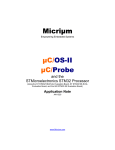
Figure 8.
UM0921
Single-channel inverter and LCD backlight driver
8
3'
*1'
1&
$
*1'
9&&
9
<
)60&B,19B&/.
9*&75B627/
6,1*/(&+$11(/,19(57(5
9
/
X+
'
6736/$B60$
8
*1'
/('B&$7+2'(
9,
5VHW
*1'
)%
6:
(1
92
1&
3%
/('B$12'(
67/''385B4)1
&
X)
5
N
5
RKP
&
X)
/&'%$&./,*+7'5,9(5
!-V
14/19
Doc ID 17247 Rev 1
UM0921
Figure 9.
Troubleshooting
Touchscreen controller
*1'
'$7$B,1
9
6&/.
6'$7
&
Q)
3%B 76&B6'$
&
X)
$
,17
3&B76&B,17
<
;
76&B<
5
N
6703( 475
9&&
76&B;
&
S)
76&B;
<
&
S)
76&B<
9,2
&
S)
76&B;
76&B<
76&B<
,1
,1
9
&
S)
*1'
;
,1
,1
8
76&B;
5
N
3%B76&B6&/
9
5
5
N
9
9
&
Q)
&
Q)
5
N
3%B 76&B6'$
5
N
3%B76&B6&/
728&+6&5((1&21752//(5
!-V
Doc ID 17247 Rev 1
15/19
Category
Bill of material (BOM)
Reference
designator
Component description
Package
Manufacturer
Manufacturer’s
ordering code /
orderable part
number
U1
Single Schmitt inverter
SOT323-5L
STMicroelectronics
74V1G14CTR
U2
White LED power supply for
large display backlight
QFN8
STMicroelectronics
STLD40DPUR
U3
4-wire resistive touchscreen
controller
QFN16
STMicroelectronics
STMPE811QTR
D1
Low-drop power Schottky
diode
SMA
STMicroelectronics
STPS1L30A
TFT-LCD
3.5" size, 320 x 240
resolution TFT-LCD
SMD
APEX
CT05350DW0000T
J1,J3
Socket 70 PS,
2.54 mm, double row,
formed contact, straight,
standard 8.5 mm,
2 x 35-way
Socket, 2.54 mm,
double row, straight,
2 x 35-way,
through-hole
Protectron
P9403-70-21
J2,J4
Header 70ps, pin,
2.54 mm, straight 70-way,
double row, gold Flash
Double row straight,
through-hole, 70-pin,
2 x 35-way
Protectron
P9103-70-12-1
J5
54-pin FPC connector
0.5 mm ZIF side-entry SMT
SMD
J6
Header, pin, 2.54 mm,
straight 10-way,
single row, gold Flash
Single row straight,
through-hole, 40-pin
ST devices
Display
Doc ID 17247 Rev 1
Connectors
and jumpers
FPC-GS200XX1GX-XA
Protectron
Supplier
Supplier
ordering code
or equivalent
Troubleshooting
16/19
Table 1.
Lapptek
Marketing
P9101-10-12-1
UM0921
Category
Bill of material (BOM) (continued)
Component description
Package
Manufacturer
C3,C4,C5,C6
2 pF
Ceramic SMD
Any
C7,C9,C10
100 nF
Ceramic SMD
Any
C1
2.2 µF
Tantulum SMD EIA
3216-18/size A
Any
C2
4.7 µF /50 V
Tantulum SMD EIA
3216-18/size A
Any
C8
10 µF/25 V
Tantulum SMD EIA
3216-18/size A
Any
R1,R2,R3,R4
R13,R14
0
SMD0805
R6
8Ω
SMD1206
R9
470 Ω
SMD0805
Any
R11,R12
4.7 kΩ
SMD0805
Any
R7,R8,R10
10 kΩ
SMD0805
Any
R5
100 kΩ
SMD0805
Any
L1
4.7 µH
SMD 1210
Capacitors
Doc ID 17247 Rev 1
Resistors
Inductors
Manufacturer’s
ordering code /
orderable part
number
Reference
designator
Supplier
Supplier
ordering code
or equivalent
Digi-Key
541-8.06FCT-ND
Digi-Key
490-5338-1-ND
UM0921
Table 1.
Any
Vishay/Dale
CRCW12068R06F
NEA
Murata Electronics
LQH32PN4R7NN0L
North America
Troubleshooting
17/19
Revision history
6
UM0921
Revision history
Table 2.
18/19
Document revision history
Date
Revision
02-Sep-2010
1
Changes
Initial release.
Doc ID 17247 Rev 1
UM0921
Please Read Carefully:
Information in this document is provided solely in connection with ST products. STMicroelectronics NV and its subsidiaries (“ST”) reserve the
right to make changes, corrections, modifications or improvements, to this document, and the products and services described herein at any
time, without notice.
All ST products are sold pursuant to ST’s terms and conditions of sale.
Purchasers are solely responsible for the choice, selection and use of the ST products and services described herein, and ST assumes no
liability whatsoever relating to the choice, selection or use of the ST products and services described herein.
No license, express or implied, by estoppel or otherwise, to any intellectual property rights is granted under this document. If any part of this
document refers to any third party products or services it shall not be deemed a license grant by ST for the use of such third party products
or services, or any intellectual property contained therein or considered as a warranty covering the use in any manner whatsoever of such
third party products or services or any intellectual property contained therein.
UNLESS OTHERWISE SET FORTH IN ST’S TERMS AND CONDITIONS OF SALE ST DISCLAIMS ANY EXPRESS OR IMPLIED
WARRANTY WITH RESPECT TO THE USE AND/OR SALE OF ST PRODUCTS INCLUDING WITHOUT LIMITATION IMPLIED
WARRANTIES OF MERCHANTABILITY, FITNESS FOR A PARTICULAR PURPOSE (AND THEIR EQUIVALENTS UNDER THE LAWS
OF ANY JURISDICTION), OR INFRINGEMENT OF ANY PATENT, COPYRIGHT OR OTHER INTELLECTUAL PROPERTY RIGHT.
UNLESS EXPRESSLY APPROVED IN WRITING BY AN AUTHORIZED ST REPRESENTATIVE, ST PRODUCTS ARE NOT
RECOMMENDED, AUTHORIZED OR WARRANTED FOR USE IN MILITARY, AIR CRAFT, SPACE, LIFE SAVING, OR LIFE SUSTAINING
APPLICATIONS, NOR IN PRODUCTS OR SYSTEMS WHERE FAILURE OR MALFUNCTION MAY RESULT IN PERSONAL INJURY,
DEATH, OR SEVERE PROPERTY OR ENVIRONMENTAL DAMAGE. ST PRODUCTS WHICH ARE NOT SPECIFIED AS "AUTOMOTIVE
GRADE" MAY ONLY BE USED IN AUTOMOTIVE APPLICATIONS AT USER’S OWN RISK.
Resale of ST products with provisions different from the statements and/or technical features set forth in this document shall immediately void
any warranty granted by ST for the ST product or service described herein and shall not create or extend in any manner whatsoever, any
liability of ST.
ST and the ST logo are trademarks or registered trademarks of ST in various countries.
Information in this document supersedes and replaces all information previously supplied.
The ST logo is a registered trademark of STMicroelectronics. All other names are the property of their respective owners.
© 2010 STMicroelectronics - All rights reserved
STMicroelectronics group of companies
Australia - Belgium - Brazil - Canada - China - Czech Republic - Finland - France - Germany - Hong Kong - India - Israel - Italy - Japan Malaysia - Malta - Morocco - Philippines - Singapore - Spain - Sweden - Switzerland - United Kingdom - United States of America
www.st.com
Doc ID 17247 Rev 1
19/19