1
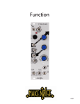
MINI SLEW is a feature packed function generator and VC slew limiter. Transient functions are generated using
the rise, fall and shape controls. Complex functions can be generated using the voltage controlled shape and
vari-out via direct CV inputs. MINI SLEW features a novel time compensation mode which permits the timing of
the transient to remain relatively constant while the shape parameter is adjusted. CV SUM mode permits a
single CV patched into rise or fall to process both parameters or two CVs patched into rise and fall to be
summed and applied to both parameters. Additional features include VC cycle (toggle on/off), end of rise and
end of fall outputs, FM input and an LED voltmeter for monitoring the amplitude of the direct positive output.
R
RISE CONTROL
F
FALL CONTROL
VO
C
LC
CYCLE LED
C
CYCLE CV TOGGLE
TS
TIME COMPENSATION and CV SUM
Push this button to toggle cycle mode on/off.
Apply a 0-5V gate signal to this input to toggle the current cycle on/off state.
T-COMP: Hold this button for >1 second to toggle time compensation of the SHAPE
control on/off.
CV SUM: Tap this button to toggle CV SUM on/off. CV SUM applies to the RISE and FALL
CV inputs. When active, CV SUM allows a single CV applied to either RISE or FALL to
affect both inputs. If two CV sources are applied to both the RISE and FALL inputs, the
CV sources are summed (added together) and applied to both inputs.
LS
CV SUM LED
This LED turns on when T-COMP mode is active.
This LED turns on when CV SUM mode is active.
SHAPE CV INPUT
Use this input to vary the SHAPE with CV. Use the SHAPE control to add an offset to
the applied control voltage.
RISE
RISE CV INPUT
FALL
FALL CV INPUT
CV
FM
MODE SELECTOR
LC
R
C
This LED indicates the cycle rate when cycle mode is active.
T-COMP LED
VARI
OUTPUT
Smoothly varying logarithmic, linear, and exponential shape control. This control affects
both Rise and Fall simultaneously. This control works as an offset when CV is applied to
the SHPE CV input. Use T-COMP mode (detailed below) to retain a relative time constant
when changing the output shape.
LT
CV
INPUT
Manually controls the amplitude level and polarity of the VARI-OUT output.
CYCLE MODE TOGGLE
CV
LED INDICATOR
VARIABLE OUTPUT CONTROL
RISE/FALL SHAPE CONTROL
PLS
CV
PANEL CONTROL
Varies the FALL time of the output transient function.
S
SHPE
COLOR KEY LEGEND
Varies the RISE time of the output transient function.
Use this input to vary the RISE time with CV. Use the RISE control to add an offset to
the applied control voltage.
VO
F
LT
S
TS
LS
LE
SHPE
FALL
RISE
VARI
FM
C
T
IN
CV
CV
CV
CV
O
Use this input to vary the FALL time with CV. Use the FALL control to add an offset
to the applied control voltage.
VARI CV INPUT
Use this input to vary the amplitude and polarity of the VARI OUT output. Use the
VARI-OUT control to add an offset to the applied control voltage. Control voltages must
be approximately +/-5V to sweep the full range. Set the VARI-OUT control to center
position for symmetrical modulation.
EXPONENTIAL FM CV INPUT
Apply a control voltage here to modulate both RISE and FALL. This input roughly tracks
2-3 octaves.
T
TRIGGER INPUT
IN
SLEW INPUT
Apply a trigger or gate to this input to initiate a transient function. You can also use
this input to re-trigger a function when CYCLE mode is active.
Apply a signal to be slewed by the RISE, FALL and associated CV inputs to this
input. Apply a gate to create a rise/hold/decay transient function. Apply any
control voltage or audio signal here to dynamically shape the input signal.
EOC EOR VO
MINI SLEW
EOC
END OF CYCLE OUTPUT
EOR
END OF RISE OUTPUT
VO
VARIABLE OUTPUT
This is the EOC output. A pulse/gate is generated whenever the output
transient completes a RISE/FALL cycle.
This is the EOR output. A pulse/gate is generated whenever the
output transient completes the RISE phase of the output transient.
This is the VARIABLE output affected by the VARI-OUT control and VARI CV input.
O
MAIN OUTPUT
LA
MAIN OUT LED ARRAY
This is the main output. This output is always positive and maximum amplitude. The +OUT LED array reflects the current amplitude state of this output.
This LED array indicates the current amplitude state of the +OUT (main output).
SAVING MODE STATES
MINI SLEW will store all mode states during power cycle intervals.
Please allow a minimum of 60 seconds to pass in order to insure that
your mode states will be retained when power is cycled off/on.