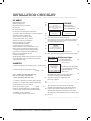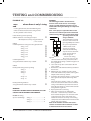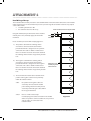
1
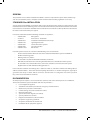
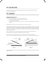
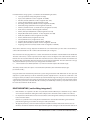
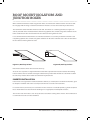
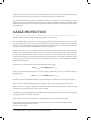
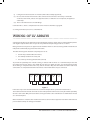
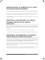
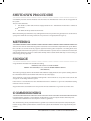
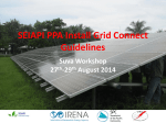
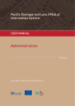
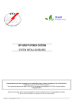
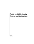
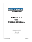
GRID-CONNECTED
PV SYSTEMS
(No Battery Storage)
SYSTEM INSTALLATION GUIDELINES
FOR THE PACIFIC ISLANDS
GRID-CONNECTED PV SYSTEMS • SYSTEM INSTALLATION GUIDELINES | a
GRID-CONNECTED
PV SYSTEMS
(No Battery Storage)
SYSTEM INSTALLATION GUIDELINES
FOR THE PACIFIC ISLANDS
These guidelines have been developed by the Sustainable Energy Industry Association of the Pacific Islands in
Collaboration with the Pacific Power Association
They represent latest industry BEST PRACTICE for the design and installation of PV Grid Connect Systems.
© Copyright 2012
www.ppa.org.fj • www.seiapi.org
While all care has been taken to ensure this guideline is free from omission and error, no responsibility can be taken
for the use of this information in the installation or design of any grid connect system.
GENERAL
The performance of a reliable installation that fulfils a customer’s expectations requires both careful design
and correct installation practice. Compliance with relevant Health and Safety regulations is necessary.
STANDARDS for INSTALLATION
System designs should follow any standards that are typically applied in the country or region where the solar
installation will occur. The following are the relevant standards in Australia, New Zealand and USA. Some Pacific
island countries and territories do follow those standards. These standards are often updated and amended so
the latest version should always be applied.
In Australia and New Zealand the following standards are applicable: …
̶ AS/NZS 3000
Wiring Rules
̶ AS 4777.1
Grid connect - Installation
̶ AS/NZS 5033
Installation of Photovoltaic (PV) Arrays
̶ AS/NZS 1768
Lightning Protection
̶ AS/NZS 4509 Stand-alone Power Systems ̶ AS/NZS 3008
Selection of cables
̶ AS/NZS 1170.2 Wind Loads
In USA PV systems must be in accordance with following codes and standards:
̶ Electrical Codes-National Electrical Code Article 690:Solar Photovoltaic Systems and NFPA 70
Uniform Solar Energy Code
̶ Building Codes- ICC, ASCE 7
̶ UL Standard 1701; Flat Plat Photovoltaic Modules and Panels
̶ IEEE 1547, Standards for Interconnecting distributed Resources with Electric Power Systems
̶ UL Standard 1741 , Standard for Inverter, converters, Controllers and Interconnection System
Equipment for use with Distributed Energy Resources
In the Australian standards Low Voltage (LV) is defined as 120V d.c. and above and Extra Low Voltage (ELV) is
defined as below 120V d.c. In the USA standard anything above 60V d.c. is considered dangerous. Typically all
grid connect PV arrays are above 120V d.c and hence considered LV. LV is dangerous and can kill a person if
they come into contact with live terminals.
DOCUMENTATION
All complex systems require a user manual for the customer. Grid-connected PV systems are no different.
The documentation for system installation that must be provided is …
• List of equipment supplied.
• Shutdown and isolation procedure for emergency and maintenance.
• Maintenance procedure and timetable.
• Commissioning sheet and installation checklist.
• Warranty information.
• System connection diagram (as installed).
• System performance estimate
• Equipment manufacturers documentation
• Array frame engineering certificate
• Array frame installation declaration and
• Handbooks for all equipment supplied.
GRID-CONNECTED PV SYSTEMS • SYSTEM INSTALLATION GUIDELINES | 1
PV MODULES
PV modules shall comply with the requirements of IEC 61730-1 and IEC 61730-2, or EN 61730-1 and EN
61730-2, or UL Standard 1703.
PV ARRAY
ORIENTATION AND TILT
In grid connected PV systems the solar array is generally mounted:
•
•
•
“Flat” on the roof (that is parallel to the slope of the roof ) OR
Integrated into the building OR
On an array frame that is tilted to fix the array at a preferred angle (usually for flat roofs or ground
mounted).
Modules that are electrically in the same string must be all in the same orientation.
For best year-round performance a fixed PV array should be mounted facing true north (± 10°) in South
Pacific and true south (± 10°) in North Pacific at an inclination equal to the latitude angle or at an angle that
will produce the best annual average performance taking into consideration: seasonal cloud patterns, local
shading and environmental factors. In the tropics this could vary due to the sun being both north and south
at different times of the year.
Note: A minimum tilt of 10° is recommended to take advantage of self-cleaning during rain periods.
Horizontally mounted arrays will require additional maintenance [cleaning].
Between latitudes 10° South and 10°North the array should be tilted at a minimum of 10 degrees.
If the array is “flat” on the roof (that is parallel to the slope of the roof ) or integrated into the building fabric,
true NORTH
true SOUTH
PV Module
LATITUDE ANGLE
e.g. for PALUA ( Lat 7° )
PV Module
LATITUDE ANGLE
e.g. for SUVA ( Lat 18° S )
The tilt angle should be approximately 18°
The tilt angle should be approximately 7°. However
because of the cloud cover in the wet season a tilt
angle of 20° would be better. This would result in
a greater energy output from the array in the dry
season.
Figure 1 a
Figure 1 b
the array will often not be at the preferred (optimum) tilt angle and in many situations will not be facing due
north or due south.
2 | GRID-CONNECTED PV SYSTEMS • SYSTEM INSTALLATION GUIDELINES
Included with the design guide is a set of tables for the following locations:
• Suva, Fiji (Latitude 18°08’S Longitude 178°25’E)
• Apia, Samoa (Latitude 13o50’ S’ Longitude 171o44’ W)
• Port Vila, Vanuatu (Latitude 17° 44’ S Longitude 168° 19’ E)
• Tarawa, Kiribati (Latitude 1°28’N, Longitude 173°2’E)
• Raratonga, Cook islands( Latitude 21°30’S, Longitude 160°0’W)
• Nuku’alofa, Tonga (Latitude 21º14’S Longitude 175º22’W)
• Honiara, Solomon Islands (Latitude 09°27’S, Longitude 159°57’E)
• Koror, Palau ( Latitude 7°20’N Longitude 134°28’E)
• Palikiri, Pohnpei FSM (Latitude: 6°54’N, Longitude: 158°13’E)
• Majuro, Marshall Islands (Latitude: 7º 12N, Longitude 171º 06E)
• Alofi, Niue (Latitude 19°04’ S. Longitude 169° 55’ W)
• Nauru (Latitude 0º55’S, Longitude 166º 91’E)
• Tuvalu (Latitude 8°31’S, Longitude 179°13’E)
• Hagåtña, Guam (Latitude 13°28’N Longitude: 144°45’E)
• Noumea, New Caledonia (Latitude 22°16’S Longitude: 166°27’E)
• Pago Pago, American Samoa (Latitude 14°16’ S Longitude: 170°42’W)
These tables show the average daily total irradiation for each month of the year for: surface at horizontal, a
surface tilted at latitude and for a surface tilted at latitude plus 15 degrees.
Also included in the design guidelines is a table derived from the Australian Solar Radiation Data Handbook.
This table is for Cairns, a coastal city located in the tropics. Hence the figures in the table would be similar to
that for some cities/islands within the Pacific Island countries because it reflects the variation in irradiation due
to different tilts and azimuths from that measured and recorded at horizontal. The table shows the average
daily total irradiation represented as a percentage of the maximum value
i.e. PV orientation is true North (azimuth = 0° ) with an inclination equal to the latitude angle.
The table provides values for a plane in 36 orientations (azimuths) and 10 inclination (tilt) angles.
[Increments of 10o ] .
Using the table from Australia will provide the system designer/installer with information on the expected
output of a system (with respect to the maximum possible output) when it is located on a roof that is not
facing true north (or south) or at an inclination equal to the latitude angle. The designer can then use the peak
sun hour data for their particular country to determine the expected peak sun hours at the orientation and tilt
angles for the system to be installed. Over the next few years SEIAPI hope that they can produce these tables
for actual sites within the Pacific islands.
ROOF MOUNTING [ not building integrated ]
•
If the modules use crystalline cells then it is preferable to allow sufficient space below the array (> 50mm
or 2 inches) for ventilation cooling. This will be subject to the constraints of the customer or architect.
•
It is important to allow sufficient clearance to facilitate self cleaning of the roof to prevent the build up of
leaves and other debris.
If fauna are a problem in the vicinity of the installation then consideration should be given to how to
prevent them gaining access under the array.(see cable protection)
•
•
All supports, brackets, screws and other metal parts should be of similar material or stainless steel to
minimise corrosion. If dissimilar metals (based on their galvanic rating) are used then the two surfaces of
GRID-CONNECTED PV SYSTEMS • SYSTEM INSTALLATION GUIDELINES | 3
the metals should be separated by using rubber washes or similar.
•
•
•
•
•
•
Where timber is used it must be suitable for long-term external use and fixed so that trapped moisture
cannot cause corrosion of the roof and/or rotting of the timber. The expected replacement time should
be stated in the system documentation.
Any roof penetrations must be suitably sealed and waterproof for the expected life of the system. If this
is not possible then this must be detailed in Maintenance Timetable
All fixings must ensure structural security when subject to the highest wind speeds for the region and
local terrain - This may require specific tests of the fixing/substrate combination on that roof.
The installer shall ensure that the array frame that they install has applicable engineering certificates
verifying that the frame meets wind loadings for that particular location.
The installer must follow the array frame suppliers/manufacturers recommendations when mounting
the array to the roof support structure to ensure that the array structure still meets wind loading
certification.
All external wiring must be protected from UV and mechanical damage in such a manner that it will last
the life of the system.(See cable Protection).
FREE STANDING PV ARRAYS
These must be wind rated in accordance with relevant wind loading standards
BUILDING INTEGRATED (BIPV) INSTALLATIONS
The installation of modules that are being used as building material e.g. tiles, building walls, sun-screens should only be
installed by a person qualified to install that particular type of building element.
4 | GRID-CONNECTED PV SYSTEMS • SYSTEM INSTALLATION GUIDELINES
ROOF MOUNT ISOLATORS AND
JUNCTION BOXES
Where roof mount isolators and/or array junction boxes are mounted on roof the installer must ensure that
the integrity of the IP rating is maintained and that no moisture can enter the isolator or junctions boxes.
The roof mount isolator should be mounted such that the switch is in a sideways position (see Figures 2a
and 2b). It should not be mounted with the switch facing upwards. The conduit entry points should be at the
lower end of the box either underneath or the face of the box facing down the roof.
It is recommended that Junction boxes are mounted so that the access to the junction box is from the side
not pointing upwards. The conduit entry points should be on the lower end of the box - either underneath or
the face of the box facing down the roof.
Figure 2a; Roof top isolator
Figure 2b; Roof top isolator
Note: Ensure that the switch does not shade the array.
All screw cover caps that are supplied with the isolator box or junction box must be installed. All mounting
holes should be silicone. Conduit entering the isolator box or junction box should have a drain hole to allow
the exit of any moisture from conduit to isolator box or junction box.
INVERTER INSTALLATION
If the inverter is designed to be installed behind the module (a.c. module) then consideration should be given
to adequate ventilation and to the ease of replacement in the event of an inverter failure.
If a central inverter (or inverters) is used and the inverter enclosure is not weatherproof (e.g. IP 54 rated) then
these should either be located inside the building or in an appropriate weatherproof enclosure.
The inverter heat sink must be clear of any obstacles to facilitate cooling of the inverter. The manufacturers
recommended clearances must be followed.
GRID-CONNECTED PV SYSTEMS • SYSTEM INSTALLATION GUIDELINES | 5
PV ARRAY ISOLATOR
A double pole load break PV array isolator (switch) shall be mounted near the inverter.
Where an inverter allows more than one input from the array an isolator shall be installed on each input and
these should be located physically beside each other near the inverter. Signage should indicate that to operate
the PV array all isolators must be operated together..
NOTE:
A breaker not rated for the open circuit d.c. voltage of the array and the d.c. short circuit current of the
array shall not be used as the PV Array Isolator.
A double pole d.c. circuit breaker can be used to perform isolation. If so, it should be non-polarised.
If the d.c. circuit breaker is polarised then the installer shall ensure that it is wired correctly.
Failure to wire correctly could lead to a fire when this isolator is operated in full sun.
AC ISOLATOR AT INVERTER
Where the inverter is not adjacent to the switchboard to which it is connected, an isolator shall be provided
at the inverter so that a person operating the switch has a clear view of any person working on the inverter.
SOLAR SUPPLY ISOLATOR IN
SWITCHBOARD
It is recommended that the interconnection of the grid connected PV system and the buildings electrical
system is undertaken at a switchboard or distribution board. This connection shall be at an a.c. solar supply
isolator located on the switchboard (or distribution board) where the solar system is connected. Throughout
the rest of this document this will be referred to as main switch inverter supply. This isolator shall be lockable.
A switch or isolator being lockable does not mean it needs a padlock or similar attached. It means that it is
able to have a tag or small plastic locking device inserted to allow a person to work on the system safely.
The intention is that the isolator locking device should include the installation of a tag/sign saying “DO NOT
SWITCH ON-PERSON WORKING ON SYSTEM” or similar.
The cable between the switchboard and inverter requires protection so it is recommended that the isolator is
a suitably rated circuit breaker.
6 | GRID-CONNECTED PV SYSTEMS • SYSTEM INSTALLATION GUIDELINES
CABLE SELECTION
All cables shall be installed in a neat and tidy manner and in accordance with any national installation
standards.
Correctly sized cables in an installation will produce the following outcomes :1. There is no excessive voltage drop (which equates to an equivalent power loss) in the cables.
2. The current in the cables will not exceed the safe current handling capability of the selected cables known
as current carrying capacity (CCC)
Selection PV String Cables
• If a fault current protection device is located in the string, then the string must be rated to carry at
least that current. For example, if the fault current protection device is rated at 8A, then the string
will need to be rated at a minimum of 8A.
• If no fault current protection is provided, then the string cable will be rated as:
CCC ≥ 1.25 × ISC MOD × (Number of Strings - 1)
Selection of PV Array Cables
• The PV array cable should be rated according to:
CCC ≥ 1.25 × ISC ARRAY
There are a large number of other system configurations possible for a grid connected system which have
their own specific requirements. The following explains the requirements of some of the more complicated
systems.
Sub-array PV Systems
A sub-array comprises a number of parallel strings of PV modules. The sub-array is installed in parallel with
other sub-arrays to form the full array. The effect of this is to decrease the potential fault current through
different parts of the system. In this case the following modifications will be necessary.
PV Array Cables
• The array cable should be rated according to:
CCC ≥ 1.25 × ISC ARRAY
PV Sub-array Cables
• If a fault current protection device is located in the sub-array cable, the sub-array cable must have a
rating equal to or greater than that of the fault current protection device.
• If no fault current protection device has been included then the current carrying capacity of the
cable must be the greater of:
1.25 × (sum of short circuit currents of all other sub‐arrays)
or
1.25 ×ISC Sub-Array
PV String Cables
• If sub-array fault current protection is used, the string cable rating will be the rated trip current of the
sub-array fault current device plus the fault current of the other stings in the sub-array:
Itrip-subarray + 1.25 × ISC MOD × (Number of Strings - 1)
• If no sub-array fault current protection device is used, the string cable rating will be:
1.25 × (sum of short circuit currents of all other strings in the array):
GRID-CONNECTED PV SYSTEMS • SYSTEM INSTALLATION GUIDELINES | 7
Cable losses between the PV array and the inverter should be as low as practical, consistent with cable size and
cost decisions, to maximise system output it is recommended that it is a maximum of 3%.
It is recommended that the voltage drop between the inverter and the point of connection of a.c. supply
should be kept as small as possible (recommended <1%) to minimise voltage rise within the installation and to
limit inverter disconnection in areas where the grid voltage may be high to decrease incidents of overvoltage
trips for inverters.
CABLE PROTECTION
All cables shall be electrically protected from fault currents that could occur.
Each solar module has a maximum reverse current rating provided by the manufacturer. If the arrays consists
of parallel strings such that the reverse current flow into a string with a fault is greater than the maximum
reverse current for the modules in that string then protection shall be provided in each string. The protection
can either be d.c. rated fuses or non-polarised d.c. rated circuit breakers.
Example: The reverse current rating for a module is 15A while the short circuit current is 5.4A. If the array
consists of 3 parallel strings and a fault occurs in one string then the potential fault current will come from
the other 2 strings which is only 10.8A (2 x 5.4) and is less than the reverse current rating so no protection is
required. However if the array consists of 4 parallel strings then the fault current could come from the other
3 strings. This current is 16.2 A (3 x 5.4) and is now greater than the reverse current rating of the module.
Protection is now required.
These fuses or d.c. circuit breakers shall have the following current rating:
1.25 x Isc of module < Fuse Rating < 2.0 x Isc of module
If the array consists of sub-arrays then each sub array shall be protected by a fuse or circuit breaker with the
following rating:
1.25 x Isc of sub-array < Fuse Rating < 2.0 x Isc of sub-array
All cables used in the installation should be securely fixed in place to minimise any movement of the cable.
Where the cables could be damaged then there should be suitable mechanical protection of the cables.
Where the presence of fauna is expected to constitute a hazard, either the wiring system shall be selected
accordingly, or special protective measures shall be adopted.
All conduits exposed to sunlight must be suitably UV rated. Not all corrugated conduits are UV rated so if using
corrugated conduit ensure that it is UV rated.
Plastic cable ties are not suitable for cables in exposed situations. They can also chaff the cables.
Cables connected to the inverter must be mechanically secured in such a manner that they cannot be
inadvertently unplugged from the inverter.
This can be achieved by:
8 | GRID-CONNECTED PV SYSTEMS • SYSTEM INSTALLATION GUIDELINES
(i) having the inverter housed in an enclosure (with cables suitably supported) ;
(ii) the use of an inverter which has the cable connection area of inverter covered by a removable
enclosure/cover which protects the supported cables so that there are no exposed, unsupported
cable loops.
(iii) The use of conduit and secure wall fittings.
Connection of a.c. and d.c. components in the same enclosure should be segregated.
d.c. wiring shall not be placed in a.c. switchboards.
WIRING OF LV ARRAYS
A dangerous situation occurs when the person installing the system is able to come in contact with the positive
and negative outputs of the solar array or sub-array when the output voltage is 60V d.c. or above.
Most grid-connected systems use approved solar modules which are connected using double insulated leads
with polarised shrouded plug and socket connections.
Therefore the dangerous situation is only likely to occur at:
•
the PV Array isolator before the inverter;
•
the roof-top isolator if one exists ;and
•
the sub-array and array junction boxes (if used).
To prevent the possibility of an installer coming in contact with live wires it is recommended practice that
one of the interconnect cables in the middle of each string (as shown in Figure 3) is left disconnected until
all the wiring is complete between the array and the inverter. Only after all isolators and other hard wired
connections are completed should the interconnect in the middle of the array be connected.
DISCONNECT
Figure 3
If the solar array is to be hard wired then the recommended procedure is provided in Attachment 1.
The installer shall ensure that all connectors used are waterproof and connected securely to avoid the possibility
of a loose connection. Only connectors of the same type from the same manufacturer are allowed to be mated
at a connection point.
When mounted on a roof, the solar module interconnect cables must be supported clear of the roof surface to
prevent debris build up or damage to insulation.
GRID-CONNECTED PV SYSTEMS • SYSTEM INSTALLATION GUIDELINES | 9
WIRING FROM LV ARRAYS TO PV ARAY
ISOLATOR NEAR INVERTER
The PV array cable shall be clearly identified as d.c. solar cable to ensure that it cannot be mistaken for a.c. cable.
To avoid confusion it is recommended that between the array and the inverter single core double insulated
solar cable is used. This cable is similar to that used for interconnecting the solar modules in the array.
It is recommended that the cable is sized such that the maximum voltage drop between the array and the
inverter is less than 3%.
EARTHING (GROUNDING) OF ARRAY
FRAMES (PROTECTIVE EARTH/
GROUND)
If the system includes a non-isolated (transformerless) inverter with no galvanic isolation then the PV module
frames (if metal) should be earthed (grounded). This is known as protective earth/ground. Refer to Attachment
1 for guidance.
It is good practice that all array frames are earthed (grounded). It is required in the US standards
It is recommended that the earthing connection is completed once the wiring of the array has been completed.
EARTHING (GROUNDING) OF ARRAYS
(FUNCTIONAL EARTH/GROUND)
If the PV array is electrically earthed (grounded), that is either the positive or negative is earthed, these arrays
cannot be connected to a transformer-less inverter with no galvanic isolation if the electrical wiring system
incorporates the multiple earth neutral system (MEN) as used in Australian and New Zealand.
For safety, it is recommended that the earthing connection is completed once the wiring of the array has been
completed. This is to ensure that the installer does not receive an electric shock by touching the unearthed
output of the array during installation.
The connection of the earth should be on the inverter side of the PV array isolator switch. This allows for the
earth to be disconnected when the array is turned off in the event of an earth fault on the array.
10 | GRID-CONNECTED PV SYSTEMS • SYSTEM INSTALLATION GUIDELINES
SHUTDOWN PROCEDURE
A shutdown procedure shall be installed near the inverter or switchboard to ensure safe de-energisation of
the system.
The procedure should be:
• Turn off the a.c. Main Switch Inverter Supply Isolator at the switchboard and then the ac Isolator at
the inverter
then
• Turn off the PV Array isolator at the Inverter.
When undertaking any work on the array cabling between the array and inverter, good practice is to disconnect
a plug in the middle of each string so that the array is then de-energised (Refer to Figure 3 ).
METERING
Some inverters have on-board metering of the instantaneous and cumulative output of the PV system. Where
this is not the case and the electricity suppliers approved metering does not provide a recording of the exact
energy output of the PV inverter system, it is recommended that a separate meter is installed to ensure that the
output of the PV inverter system is recorded. This will help if the customer thinks that they are not receiving as
much energy as they expected.
SIGNAGE
A sign should be included in the switchboard stating:
‘WARNING’, ‘DUAL SUPPLY’ and ‘ISOLATE BOTH
NORMAL AND INVERTER(or solar) SUPPLIES BEFORE WORKING ON THIS
SWITCHBOARD’,
The normal grid supply shall be labelled Main Switch Normal Supply while the solar system isolating switch in
the switchboard shall be labelled Main Switch Inverter (or solar) Supply.
There should be a sign on the switchboard stating what is the maximum d.c. array short circuit current and
array open circuit voltage from the system.
If the inverter is not mounted near the switchboard then there should be a sign in the switchboard stating
where the inverter is located.
Any junctions boxes used between the array and the inverter should have a sign “Solar d.c.” on the cover.
COMMISSIONING
Included with this guideline is an installation checklist which can be used by the installer when they have
completed the installation to ensure they have met these guidelines.
The commissioning sheets provided with these guidelines (or similar document) shall be completed by the
installer. A copy shall be provided to the customer in the system documentation and a copy retained by the
installer.
GRID-CONNECTED PV SYSTEMS • SYSTEM INSTALLATION GUIDELINES | 11
INSTALLATION CHECKLIST
PV ARRAY
Mounted flat on roof
Building integrated Mounted on tilted array frame PV Array tilt ……………………°
PV Array orientation
……………………°
PV Array is securely fixed and installed in
accordance with manufacturers recommendations
Any timber used is suitable for
external use or is properly sealed
No dissimilar metals are in contact
with the array frames or supports
Roof penetrations are suitably
sealed and weatherproofed
PV wiring losses are less than 1%
at the maximum current output of the array
Where PV array comprises multiple strings
- string protection has been provided when
required in accordance with AS/NZS 5033
Wiring is protected from UV and
mechanical damage
Weatherproof isolator ( where required by local
electricity distributor) is mounted immediately
adjacent to the array
¨
¨
¨
¨
¨
¨
¨
¨
¨
¨
WARNING
Dual Supply
Isolate Both Normal and Solar
Supplies before working on this
switchboard
SIGNAGE
( White on Red )
is permanently fixed
on the switchboard.
¨
MAIN SWITCH
Normal Supply
MAIN SWITCH
Solar Supply
is permanently fixed at the
main solar switch and normal supply
¨
¨
If the solar system is connected to a distribution board then
the following sign is located on main switchboard and all
intermediate distribution boards
WARNING
DUAL SUPPLY
ISOLATE SOLAR SUPPLY AT
DISTRIBUTION BOARD DB???
¨
Where the inverter is not adjacent to the Main switchboard, location information is provided
Warning and Advisory Signs ¨
SOLAR DC
is permanently fixed on array junction boxes
¨
INVERTER
( Black on White )
Lockable Double pole d.c isolator [ or d.c. circuit breaker
¨
is mounted close to input of the inverter
( rating. ..….A )
] Emergency information
Fire
is permanently fixed on the
main switchboard
¨
If d.c. isolator is of the polarised type
then it is correctly connected to
ensure operation under full load
¨
a.c. Isolator is mounted on output of the inverter
¨
Lockable a.c. circuit breaker mounted within the ¨
switchboard to act as main switch
for the PV / inverter system. ( rating …….. A )
Inverter is inside building or in weatherproof
enclosure with adequate space and ventilation
d.c. CABLING is clearly identified
–d.c. or similar at least every 3 metres
¨
¨
( White on Red )
¨
Shutdown procedure is permanently fixed
at inverter and/or on main switchboard
Any other signage as required by local
Electricity Supplier
¨
____________________________________________
This checklist is based on the GC Installation
Guidelines developed by the Sustainable Energy
Industry Associations of the Pacific Islands in
collaboration with the Pacific Power Association. .
The Guidelines demonstrate the latest industry “best
practice”.
____________________________________________
12 | GRID-CONNECTED PV SYSTEMS • SYSTEM INSTALLATION GUIDELINES
AUTHORISATION : I, ……………………………………
following system has been installed to the standard indicated by these guidelines
Name of the person for whom the system was installed …………………………………………………………
Location of system …………………………………………………………………………………………………
signed ……………………………………….. Date :
/
/
Attach a separate sheet detailing any departures
GRID-CONNECTED PV SYSTEMS • SYSTEM INSTALLATION GUIDELINES | 13
TESTING and COMMISSIONING
PV ARRAY- d.c.
NOTE : and
where there is only 1 string
no array junction box, then the following tests
will be conducted between the string and the
PV array isolator at the inverter.
Isolate PV string and array wiring
CHECK that there is no voltage on input
OR output sides of any array junction box
¨
( where installed )
CHECK
Continuity between strings and array junction box
String 1 +ve String 1 -ve String 2 +ve String 2 -ve String 3 +ve String 3 -ve
......
Continuity between
array junction box and PV array isolator
¨
¨
¨
¨
¨
¨
¨
CHECK
Polarity of PV string and array wiring
String 1 String 2 String 3 ...... Array +ve Array -ve ¨
¨
¨
¨
¨
¨
Polarity of wiring between
array junction box and PV array isolator
¨
WARNING:
IF POLARITY OF ONE STRING IS REVERSED, THIS CAN
CAUSE A FIRE IN THE ARRAY JUNCTION BOX.
RECORD PV string
open circuit Voltage
String 1
String 2
String 3
…………………V
…………………V
…………………V
WARNING:
The following procedures describe how to
measure short circuit currents - the voltages
can be very high and if the procedures are not
followed then arcing and damage to components
could occur.
Note : Some projects require that short circuit
currents are recorded as part of the contractual
commissioning, otherwise a record of the actual
operating current of each
FROM PV STRING
string is sufficient.
This could be done by using
the meter on the inverter or
by using a clamp meter when
the system is operational.
OFF
OFF
1. Where short circuit
currents are required
undertake the following
WIRE
steps to measure the short
LINK
circuit current safely as
CLAMP
shown in Figure 4
METER
Ensure each string
Figure 3
Figure 4
fuse ( where required ) is not
connected or that LV array is disconnected in
the middle of the string as shown in Figure 2 of
these guidelines.
2. Leave solar array cable connected to the PV
array isolator.
3. Remove the cable from the PV Array isolator to
the inverter.
4. With the PV array isolator off - put a link or
small cable between the positive and negative
outputs of the PV array isolator.
5. Install the string fuse for string 1 or connect the
ELV segments to complete the wiring of the
string.
Turn on PV array isolator - using a d.c. clamp
meter measure the DC short circuit current for
String 1. Turn off PV array isolator. Disconnect
string fuse for string 1 or remove links to break
string into ELV segments..
6. Repeat point 5 for each string
7. After each string has been individually
measured – ensure PV array isolator is offthen install all string fuses or connect the ELV
segments of each string. Turn on PV array
isolator and measure d.c. Array current using
clamp meter. Turn off switch and remove link in
output of PV array isolator.
Note-Some installers use their own test d.c.
isolator connected to the installed d.c isolator
to measure the short circuit current.
14 | GRID-CONNECTED PV SYSTEMS • SYSTEM INSTALLATION GUIDELINES
Where short circuit currents are not required then
record the operating current/s after Start-Up of System.
RECORD
Short circuit Currents String 1
Refer to system manual for the inverter
and follow start-up procedure.
…………………A
( where required )
String 2
Start-Up of System
………………… A
String 3 ………………… A
String 4 …………………. A
Array ………………… A
Irradiance at time of recording the current …………W/m2
With the PV array isolator OFF
CHECK
continuity between PV array isolator and inverter
Array +ve Array -ve ¨
¨
CHECK polarity between
the PV array isolator and inverter
¨
RECORD
Open circuit voltage at input side
of the PV array isolator This generally involves turning on the PV array
isolator followed by the main switch solar supply
but the procedures as recommended by the inverter
manufacturer must be followed.
System connects to grid [ Not Before 60 seconds ]
When the main switch Solar supply is turned ON
- follow the inverter start-up procedure Voltage at d.c. input of inverter
……..…..……..V
Voltage is within operating limits of inverter
Voltage at a.c. output of inverter Input power of the inverter ¨
¨
……..…..……..V
..……………..……..W
( where available )
..…………….V
Output power of the inverter
WARNING: If polarity is reversed at the inverter
damage may occur which is generally not covered
under warranty
INVERTER – a.c.
..……………..……..W
( where available )
Output power as expected
¨
Turn main switch Solar supply OFF
System disconnects from grid within 2 secs
¨
PV operating current
Ensure that the a.c. normal supply is isolated
and the main switch Solar supply is OFF
CHECK
Continuity between Inverter & main switch Solar supply
Line ¨
Neutral ¨
CHECK
Continuity between main switch Solar supply & kWh
meter
Line ¨
Neutral ¨
CHECK polarity at the Inverter
and the main switch Solar supply ¨
CHECK polarity at the output
of main switch Solar supply from the kWh meter
Initial reading of kWh meter ………………………….
Installer Name……………………………….
¨
1. Where there’s only one string in the array record the
operating current after Start-Up of System.
2. If more than one string - turn off the inverter, the a.c.
main switch and PV array isolator. Isolate all strings.
3. With one string connected at a time turn system back
on and record the operating current of that string.
Repeat 2 and 3 above
until all string currents have been recorded.
NOTE: Unless you have a solar irradiance meter than any
string current tests should be performed on a bright sunny
day with no cloud. This is to avoid varied readings due to
cloud cover.
RECORD
operating currents :
String 1 …………………A
String 2 …………………A
String 3 …………………A
String 4 ………………….A
Array ………………… A
Signed…………………………….Date………………..
GRID-CONNECTED PV SYSTEMS • SYSTEM INSTALLATION GUIDELINES | 15
ATTACHMENT 1
PV module earthing (grounding)
It is especially important that PV module frame earthing (grounding) is provided when using non-isolated
‘transformerless’ inverters.
Non-isolated inverters operate at high frequency. There will be an a.c. component on the d.c. supply.
This is capacitively coupled to the module frames producing an a.c. voltage. While not likely to be lethal the
electrostatic charge, if not depleted by earthing (grounding), could be enough to frighten and possibly cause
a person to fall off the roof i.e. the system owner, while cleaning modules.
Please note …
Aluminium oxide forms on the surface of aluminium exposed to the air. It is an insulator. Anodising is just a
thicker layer of coloured aluminium oxide.
Earthing (grounding) the array structure does not earth the module frames. Module frames must be individually
earthed using external tooth star washers to penetrate the oxide coating. The connection is then sealed [ using
spray paint taking care that there is no overspray on the module surface ]. Excellent special purpose earthing
lugs are available from the US which enable “gas tight” connections to module frames. Earth (ground) wires
must be run so that the removal of one component (e.g. module) does not interrupt the earthing (grounding)
of other parts of a system. In other words daisy chaining earth connections is not permitted.
16 | GRID-CONNECTED PV SYSTEMS • SYSTEM INSTALLATION GUIDELINES
ATTACHMENT 2
Hard Wiring of Arrays
The method outlined in this procedure is to be followed if the interconnection between the solar modules
will be hard wired. It has been written to prevent a person being able to touch the two live array output
cables either within :
• a module junction box OR
• the isolator located near the array.
Double insulated positive and negative cables
Using this method, the junction boxes on the modules
will only have a live (nominal) supply of 12V or 24V
maximum.
DOUBLE POLE
ISOLATOR
Please read this procedure while studying figure 2.1.
a) The positive cable from the isolating switch
or breaker is connected to the solar module
junction box which is designated as the positive
connection. This cable is double- insulated and
there are no other electrical connections between
the isolating switch and the array positive junction
box.
b) The negative cable from the isolating switch
or breaker is connected to the solar module
junction box which is designated as the negative
connection. This cable is double-insulated and
there are no other electrical connections between
the isolating switch and the array positive junction
box.
'MultiContact' style
insulated plug and
socket connector
c) To ensure that the installer does not work on live
positive and negative cables in close proximity
within the isolation switch:
either the positive and negative cables are
electrically connected to the double
pole isolating switch or breaker prior to
electrically terminating the cables within
the array junction boxes
and/or
there is a ‘multi-contact’ style
insulated plug and socket connection in the middle
of the array which is connected after the array is wired
and the cables are connected in the
isolation switch.
Figure 2.1
GRID-CONNECTED PV SYSTEMS • SYSTEM INSTALLATION GUIDELINES | 17
Appendix 1
Table of Abbreviations and Acronyms
d.c.
Direct current
a.c.
Alternating current
AS/NZS
Australia Standard/New Zealand Standard
UL
Underwriters Laboratory
ICC
International Code Council
NFPA
National fire Protection Association
ASCE
American Society of Civil Engineers
IEEE
Institute of Electrical and Electronics Engineers
Wh
Watt hours
kWh
Kilowatt hours
W
Watts
WP
Watts peak
H
hours
V
Volts
A
Amps
PV
Photovoltaic
PSH
Peak sun hours (kWh/m2)
kWh/m2
Kilowatt hours/metres squared
Voc
Open circuit voltage (volts)
Vmp
Maximum power point voltage (volts)
Isc
Short circuit current (amps)
Imp
Maximum power point current (amps)
LV
Low Voltage (>=120V DC in Australian Standards)
ELV
Extra Low Voltage (<120V DC in Australian Standards)
IEC
International Electrotechnical Commission
EN
European Standard
UV
Ultraviolet light
IP
Ingress protection
MEN
Multiple earth neutral
+ ve
Positive
- ve
Negative
18 | GRID-CONNECTED PV SYSTEMS • SYSTEM INSTALLATION GUIDELINES
20 | GRID-CONNECTED PV SYSTEMS • SYSTEM INSTALLATION GUIDELINES