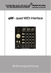
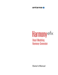
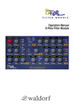
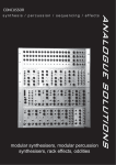
1
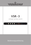
Ownerʻ‘s Manual
Owner's Manual - VERMONA*modular qMI - quad MIDI Interface
Introduction
Patch your VCO, VCF and VCA, add a few envelopes and LFOs and your
modular synthesizer system is ready to go. Now, connect your MIDI/CVinterface and start playing. This is great, however, there may be some or
even lots of unused modules left in your frame, not being used for this
patch. You may have useful applications for these but how to address them?
Analogue modular systems are mainly used monophonically. Therefore,
almost all MIDI/CV-modules are limited to monophonic output. On the
other hand, the bigger the modular system, the more possibilities to
address modules are needed.
We have developed the qMI - quad MIDI interface for exactly this scenario.
Whether you need four independent patches, layering of sounds, a rotating
voice assignment or even a polyphonic sound - the qMI - quad MIDI interface will help you, getting the most out of your modular system.
The VERMONA-team
Erlbach/Vogtland, Germany
Important Safety Information
1.
Read these instructions.
2.
Keep these instructions. Alway include these instructions when passing
the product on to third parties.
3.
Heed all warnings.
4.
Follow all instructions.
5.
Do not use this apparatus near water.
6.
Only clean the product when it is not connected to the mains power
supply. Clean only with a dry cloth.
7.
Do not block any ventilation openings. Install in accordance with the
manufacturer's instructions.
8.
Do not install near any heat sources such as radiators, heat registers,
stoves, or other apparatus (including amplifiers) that produce heat.
9.
Do not defeat the safety purpose of the polarized or grounding-type
plug. A polarized plug has two blades and a third grounding prong.
The wide blade or the third prong are provided for your safety. If the
provided plug does not fit into your outlet, consult an electrician for
replacement of the obsolete outlet.
10. Protect the power cord from being walked on or pinched, particularly
at plugs, convenience receptacles, and the point where they exit from
the apparatus.
-2-
Owner's Manual - VERMONA*modular qMI - quad MIDI Interface
11. Only use attachments/accessories specified by the manufacturer.
12. Use only with the cart, stand, tripod, bracket, or table specified by the
manufacturer, or sold with the apparatus. When a cart is used, use
caution when moving the cart/apparatus combination to avoid injury
from tip-over.
13. Unplug this apparatus during lightning storms or when unused for
long periods of time.
14. Refer all servicing to qualified service personnel.Servicing is required
when the apparatus has been damaged in any way, such as power supply cord or plug is damaged, liquid has been spilled or objects have
fallen into the apparatus, when the apparatus has been exposed to rain
or moisture, does not operate normally, or has been dropped.
15. To completely disconnect this apparatus from the AC mains,
disconnect the power supply cord plug from the AC receptacle.
16. WARNING: To reduce the risk of fire or electric shock, do not expose
this apparatus to rain or moisture.
17. Do not expose this equipment to dripping or splashing and ensure that
no objects filled with liquids, such as vases, are placed on the equipment.
18. The mains plug of the power supply cord shall remain readily accessible.
Installation
• Ensure that the room in which you use this product is wired in accordance
with the local electrical code and checked by a qualified inspector.
• Only use this product indoors.
• Do not install the product in hot, humid, or excessively dusty locations, in
direct sunlight or in locations where it is exposed to externally generated
vibrations.
• Do not place burning objects (e.g. candles) on top of or near the product.
• If condensation has formed on the product, e.g. because it was moved
from a cold environment to a warm one, allow the product to acclimatize
to room temperature before using it.
• Do not overload wall outlets and extension cables as this may result in
fire and electric shock.
-3-
Owner's Manual - VERMONA*modular qMI - quad MIDI Interface
Table of Contents
1 Introduction ..................................................................................................................2
2 Important Safety Information ...............................................................................2
3 Table of Contents ......................................................................................................4
4 Getting Started ............................................................................................................6
4.1. Setup ................................................................................................6
5 General ...........................................................................................................................8
5.1. Connections and Controls .................................................................9
5.1.1. (1) MIDI-input (MIDI IN) ................................................................10
5.1.2. (2) Rotary-switch (1 - 16) .............................................................10
5.1.3. (3) EDIT push-button ...................................................................10
5.1.4. (4) MIDI CH push-button ..............................................................10
5.1.5. (5) PLAYMODE selector .................................................................10
5.1.6. (6) CV/Gate channel push-buttons (1, 2, 3, 4) ..............................10
5.1.7. (7) GATE outputs 1-4 ...................................................................10
5.1.8. (8) Key-CV outputs 1-4 (1V/OCT) ................................................11
5.1.9. (9) / (10) Control voltage outputs 1-4 (CV1 / CV2) .......................11
5.1.10. (11) RESET output .......................................................................11
5.1.11. (12) Clock division outputs (1/4, 1/8, 1/16, 1/8T) .....................11
5.1.12. Circuit board jumpers (CV / GATE) .............................................12
6 Utilization ...................................................................................................................13
6.1. Setting the MIDI-Channels...............................................................13
6.2. Connecting the Gate- and Key-CV-Outputs ....................................13
6.3. PLAYMODE ......................................................................................15
6.3.1. Monophonic playmode 1 (M1) ......................................................15
6.3.2. Monophonic playmode 2 (M2) ......................................................16
6.3.3. Polyphonic playmode (POLY) ........................................................16
6.4. Control voltage outputs (CV1 / CV2) ...............................................17
6.5. Clock division outputs (1/4, 1/8, 1/16, 1/8T) .................................19
6.6. Reset-output (RESET) ......................................................................19
6.7. System settings (OTHER) .................................................................20
-4-
Owner's Manual - VERMONA*modular qMI - quad MIDI Interface
7 Declaration of Conformity...................................................................................22
-5-
Owner's Manual - VERMONA*modular qMI - quad MIDI Interface
Getting Started
To ensure top quality, we carefully inspected the qMI - quad MIDI interface before packaging. Nevertheless, the module could have been damaged
during transportation. Therefore, we ask you to take a serious look at the
instrument when unpacking. Do not hesitate to contact us, should there be
anything unusual with the unit or its packaging.
You should find the following items in the box:
• 1 qMI - quad MIDI interface
• 1 system connection chord (16pin, compatible to Doepfer's A100)
• 4 rack mounting screws 3 x 6mm and 4 washers
• this manual
Setup
The qMI - quad MIDI interface was designed to work in modular synthesizer systems using the common euro rack format. Its power supply,
connectors and dimensions match the specifications of Doepfer's A100
modular synthesizer system and compatible units. To mount the module
into your system's frame, carry out the following steps:
1.
Switch off the power supply. For safety reasons, also remove the
detachable power cable from your frame.
2.
Connect the supplied ribbon cable to the qMI - quad MIDI interface's
rear. The corresponding plug socket is protected against reverse
polarity. The ribbon cable will only fit in one direction.
3.
Connect the ribbon cable's other side to an empty plug-socket of your
frame's system bus. Make sure that the color coded side of the cable
points downwards. (see picture "Connecting the qMI to the systembus" on page 7)
ATTENTION
Connecting the ribbon cable with reverse polarity
may lead to damage of your module when powering
the system
-6-
Owner's Manual - VERMONA*modular qMI - quad MIDI Interface
qMI
ribbon cable
system bus
Picture 1: Connecting the qMI to the systembus
4.
Mount the qMI - quad MIDI interface to your modular frame. The unit
requires a width of 24 HP (horizontal pitch) and is rack-mounted with
the four supplied screws.
NOTE
5.
To protect the unit's surface of scratches, use the 3 mm
flat plastic washers that come with your module.
Reconnect the power chord to your frame and switch on the power
supply. The module is now ready to work. Press the MIDI CH- or EDIT
push-button to verify if the qMI - quad MIDI interface is correctly
supplied with power. If so, pressing the push-button will turn a green
LED on. Press again to leave this menu.
NOTE
In difference to many other CV/MIDI interfaces for
modular synthesizer systems, the qMI - quad MIDI
interface does not need an additional 5 volts adapter
for the system bus.
To find out how to connect the qMI - quad MIDI interface to your other
modules in your system, read the following sections.
-7-
Owner's Manual - VERMONA*modular qMI - quad MIDI Interface
General
The qMI - quad MIDI Interface is a MIDI to CV converter. It transforms
MIDI-notes, MIDI-controller-data and clock signals into analogue voltages
and gate signals. The module offers four channels (referred to as CV/Gate
channels) with individual CV- and gate outputs for note outputs. In addition, the module offers two CV-outputs per channel to control variable
parameters - independently or in combination. This makes the conversion
of monophonic and polyphonic MIDI-sequences with additional use of MIDIcontrollers possible with your modular synthesizer system.
Picture 2: CV/Gate channel of the qMI - quad MIDI Interface
The CV-output for pitches follow the established standard of 1 volt per
octave. All current oscillator modules and most vintage synthesizers should
support this conversion scheme.
The gate connector provides 10 volts output with positive polarity. Again,
this voltage is accepted by almost all modules at their gate inputs, e.g.
envelopes, switches, reset-inputs of LFOs, start/stop inputs of sequencers
etc. Clock and reset-outputs also provide 10 volts with positive polarity.
CV outputs 1 and 2 provide continuous control voltages between 0 and 5
volts, deriving from different MIDI-controllers.
-8-
Owner's Manual - VERMONA*modular qMI - quad MIDI Interface
Connections and Controls
The qMI - quad MIDI interface offers its MIDI input with all corresponding
control elements to the left. The module's right section provides four output
jacks for the four channels. These carry the analogue control voltages having been converted from the MIDI input. From here, you connect to your
system's modules.
The qMI - quad MIDI interface processes MIDI-notes, velocity, pitch bend
commands, a choice of MIDI-controllers as well as MIDI-clock. All these signals are converted into analogue CV-, gate- and clock-signals. All 16 MIDIchannels are recognized. Notes and controllers of up to four different MIDIchannels can be converted independently.
Picture 3: Controls and Connectors of the qMI - quad MIDI Interface
-9-
Owner's Manual - VERMONA*modular qMI - quad MIDI Interface
(1) MIDI-input (MIDI IN)
The MIDI-input will receive data from a keyboard's, hardwaresequencer's or from a DAW's MIDI-output. Use a standard MIDI cable for
connection (5-pin DIN).
(2) Rotary-switch (1 - 16)
This 16-position-rotary-switch works in combination with the MIDI CH
(3) and EDIT (4) push-buttons. Here, you carry out assignments for
MIDI-channels and MIDI-controllers.
(3) EDIT push-button
This push-button works in combination with the rotary-switch (2). It
allows assignment of MIDI-controllers to CV1- and CV2-outputs (9 and
10) of the four CV/Gate channels as well as further system settings.
(4) MIDI CH push-button
This push-button works in combination with the rotary-switch (2). It
allows assignment of one or more MIDI-channels to the four CV/Gate
output channels.
(5) PLAYMODE selector
This switch selects the playmode. Available are one polyphonic (POLY)
and two monophonic (M1, M2) modes. Find detailed descriptions of the
playmodes in section "PLAYMODE" on page 15.
(6) CV/Gate channel push-buttons (1, 2, 3, 4)
These push-buttons serve to assign MIDI-channels and edit-functions to
the four CV/Gate channels. Before any assignment is possible, you need
to enter the MIDI- or edit-menu. The corresponding red LEDs above the
CV/Gate push-buttons display current as well as existing assignments.
Please also read sections "Setting the MIDI-Channels" on page 13 and
"Control voltage outputs (CV1 / CV2)" on page 17.
(7) GATE outputs 1-4
These connectors output gate-signals that equal the note lengths
received at the MIDI-input. Gate-voltage is 10 volts with positive polarity. For use, please refer to section "Connecting the Gate- and KeyCV-Outputs" on page 13.
- 10 -
Owner's Manual - VERMONA*modular qMI - quad MIDI Interface
(8) Key-CV outputs 1-4 (1V/OCT)
The connectors output control voltages that equal the note pitches
received at the MIDI-input. Key-CV voltage ranges from 0 to 5 volts following a conversion scheme of 1 volt per octave. For use, please refer to
section "Connecting the Gate- and Key-CV-Outputs" on page 13.
(9) / (10) Control voltage outputs 1-4 (CV1 / CV2)
These connectors output continuously variable control voltages ranging
between 0 and 5 volts. These control-voltages derive from different
assignable MIDI-controllers. For use, please refer to section "Control
voltage outputs (CV1 / CV2)" on page 17.
(11) RESET output
The reset-output interprets the status of a MIDI-sequencer. With the
reception of a stop-command, a permanent voltage of +10 volts is
being output. With the reception of MIDI-start or continue-command,
the output's voltage is set to 0 volt. For use, please refer to section
"Reset-output (RESET)" on page 19.
(12) Clock division outputs (1/4, 1/8, 1/16, 1/8T)
These four connectors output clock-signals deriving from a received
MIDI-clock of a connected sequencer. Each output carries a different
clock divided signal. Clock impulses are sent with 10 volts and positive
polarity. For use, please refer to section "Clock division outputs (1/4,
1/8, 1/16, 1/8T)" on page 19.
- 11 -
Owner's Manual - VERMONA*modular qMI - quad MIDI Interface
Circuit board jumpers (CV / GATE)
Two plug-in-jumpers to the side of the module's circuit board can be
used to send key-CV- and gate voltages of CV/Gate channel 1 to the
system bus. With the plug-in-jumper set next to the CV/GATE label, the
connection to the system bus is active. This way, front panel cable
connections for this function are no longer necessary with the receiving
modules being mounted on the same bus circuit board (resp. a CV/Gate
connection has been made across several bus circuit boards). With the
jumper set next to the OFF label, the connection to the system bus is
inactive.
CV1 / GATE1 not on systembus
CV1 / GATE1
on systembus
Picture 4: Jumper settings for CV1 and Gate
NOTE
A distribution of key-CV- and gate-signals across the
system bus is useful where multiple oscillators and
envelopes are present. Here, the internal signal distribution replaces the need for multiples. Unfortunately,
not all oscillators support system bus distribution. If
this is the case, key-CV has to be patched the usual
way.
- 12 -
Owner's Manual - VERMONA*modular qMI - quad MIDI Interface
Utilization
Setting the MIDI-Channels
1.
Press MIDI CH (4), the corresponding green LED will be lit.
2.
Select the MIDI-channel (1-16) using the rotary-switch (2).
3.
Press one or multiple push-buttons (6) to select the CV/Gate channels
to be addressed from the selected MIDI-channel. The corresponding
red LEDs will be lit.
4.
To assign another channel, select another MIDI-channel using the
rotary-switch (2) and press one or more CV/Gate channel push-buttons (6) consecutively.
5.
Press MIDI CH (3) once more to exit channel assignment mode. The
green LED will turn off. The assignments are automatically stored and
kept even with the modular system being switched off.
Connecting the Gate- and Key-CV-Outputs
Once the MIDI-channels are assigned, the qMI - quad MIDI interface is
ready to play. However, you will need to assign the key-CV- and gate-outputs to their targets.
For example, a simple synthesizer patch is build out of a VCO, a VCF and a
VCA. The filter's cutoff-frequency and the VCA are controlled by an envelope generator. The first connection is the assignment of key-CV to the
oscillator (VCO). Patch a cable from the module's corresponding 1V/OCT
output to the VCO's CV-input. Many oscillators offer more than a single CVinput. The input to handle key-CV often has a different labeling, depending
on the manufacturer, e.g. CV1, 1V/Oct-In or Main-CV.
When using multiple VCOs, the key-CV needs to be distributed. You may
use the system bus to transfer key-CV to the oscillators if using channel 1
of the qMI - quad MIDI interface. Unfortunately, not all oscillators support
this handy feature. Please consult the respective documentations. In case,
bus-CV is not supported, key-CV has to be distributed using a multiple.
Note that using multiples may cause a loss of signal quality which may
result in pitch corruption. Here, we recommend using buffered multiples.
- 13 -
Owner's Manual - VERMONA*modular qMI - quad MIDI Interface
NOTE
Key-CV may also be used to modulate the filter's cutoff
frequency. This function is referred to as key tracking or
key follow. Here, the filter will open in relation to incoming pitch. Only few filter modules will support Bus-CV.
Usually, a patch chord connection is required. To adjust
the intensity of the key tracking function, we recommend using a CV-input with attenuator.
The qMI - quad MIDI interface's gate signal triggers the envelope which
controls the VCA. If your patch requires two or more envelope generators,
e.g. for separate filter control or the VCO's pulse width, the gate signal
needs to be distributed to trigger all envelopes simultaneously. This is
either done via channel 1 across the system bus or by using a multiple.
There is no need for buffered multiples when duplicating gate-signals.
NOTE
When playing monophonic patches using the qMI quad MIDI interface, no multiples are needed to distribute key-CVs to up to four oscillators. The same goes
for the gate-signals for up to four envelope generators.
With all CV/Gate-channels set to the same MIDI-channel, every output will carry the same note values and the
qMI - quad MIDI interface itself acts as a distributor.
- 14 -
Owner's Manual - VERMONA*modular qMI - quad MIDI Interface
PLAYMODE
The PLAYMODE switch determines in what way incoming MIDI-notes are
distributed to the CV/Gate channels. Playmode is a global setting for the
qMI - quad MIDI interface. Naturally, you won't be able to play a threenote-chord by assigning just two CV/Gate channels to a MIDI-channel.
Playmode can be switched while playing a sequence. This will sometime
result in interesting effects.
Monophonic playmode 1 (M1)
With this PLAYMODE enabled, all combined CV/Gate channels set to the
same MIDI-channel are played in parallel. Key-CV and gate outs transfer the
same pitches and note lengths. In addition, M1 is the standard mode for
individual, uncombined channels. This mode won't allow for rotating or
polyphonic voice assignments.
With channels 1, 2 and 3 being combined on MIDI-channel 1 and channel 4
reacting to MIDI-channel 2, channel 4 will still be played independently in
M1-mode, disregarding the selected PLAYMODE which may have been set to
M2 or POLY.
NOTE
To distribute identical key-CV- and gate-signals to
multiple oscillators and envelopes, you may also use
multiples. Here, only a single CV/Gate-channel is needed. Mode M1 is best suited for independent
sequences. It allows playing up to four independent
melodies, arpeggios or sequences simultaneously.
Equally, it is possible to trigger four individual drum
modules using the gate outputs, e.g. from MFB or Analogue Solutions.
- 15 -
Owner's Manual - VERMONA*modular qMI - quad MIDI Interface
Monophonic playmode 2 (M2)
This PLAYMODE is monophonic, too. Here, the combined CV/Gate channels
are not addressed in parallel but one after another. The first MIDI-note will
trigger e.g. channel 1, the next channel 2 and so on...
Mode M2 offers multiple possibilities. Control multiple patches with identical settings but spread the "voices" across the stereo panorama. The result
will be a rhythmical jumping stereo-sound, well suited for fast sequences
and arpeggios.
With oscillators, filters and modulators being set differently on all participating channels and maybe even spread across the stereo image, a
sequence can drastically change its sound when changing between modes
M1 and M2. Although, the same notes are used, mode M2 will give the
impression of (up to) four new sequences, due to our ear separating the
different sounds from each other. Using an odd number of notes per beat
will further increase this effect. Try to change between modes M1 and M2
frequently to discover new melodies!
Although it is tempting to use all four channels for voice rotation, notice
that also two channels will still allow for interesting possibilities due to constant changes.
Arpeggio-like mini-sequences in mode M2 can be achieved by using different oscillator tunings for all four channels. Start your sequence by playing
the same MIDI-note and adjust the oscillators. The mini-sequence is a
result of the voice rotation. Changing the MIDI-note will "transpose the
arpeggio".
Polyphonic playmode (POLY)
This playmode allows all combined channels to be played polyphonically.
This way, your modular synthesizer system can be played with up to fourvoice polyphony. The advantage of polyphony in a modular synthesizer system is the possibility to adjust all voices' sounds individually. Even slight
variations of oscillator- and filter-settings will clearly enhance the liveliness
in a chord.
For example: With the qMI - quad MIDI interface being configured to fourvoice polyphony and four received notes held, the fifth received MIDI-note
will replace the oldest (longest held) note.
- 16 -
Owner's Manual - VERMONA*modular qMI - quad MIDI Interface
Polyphony in modular synthesizer systems always comes at expenses. All
modules in a patch need to be available in appropriate numbers. For example, even a simple patch will require four VCOs, four filters, four VCAs and
eight envelope generators. Also, a corresponding mixer and multiples have
to be available. More complex patches will, of course, lead to more complex
module configurations. An alternative solution could be the use of modules
that combine multiple functions in a single unit, such as Doepfer's A-111-5
or Cwejman's VM-1. Both offer a complete synthesizer voice in a unit that
only needs to be assigned to key-CV/GATE. Analogue Solutions also offers
SY02 and SY03 modules that each combine a filter and a VCA. Finally, there
are modules available that offer two or four identical functions in a single
space-saving unit, such as four envelope generators, LFOs or VCAs.
Control voltage outputs (CV1 / CV2)
In addition to the outputs for key-CV and gate, each of the qMI - quad
MIDI interface's four channels offers two control voltage outputs. These
outputs provide CV-signals with up to 5 volts. The control voltages provided here derive from incoming MIDI-controller signals. Each CV-output
can be assigned to one of four possible MIDI-controllers.
For output CV1 select between:
1
MOD WHEEL (MIDI-CC# 1)
2
AFTERTOUCH
3
VELOCITY
4
VOLUME (MIDI-CC# 7)
For output CV2 select between:
5
MOD WHEEL (MIDI-CC# 1)
6
AFTERTOUCH
7
VELOCITY
8
PITCH BEND
- 17 -
Owner's Manual - VERMONA*modular qMI - quad MIDI Interface
NOTE
With PITCH BEND being selected for CV2, the voltage
range changes to -2.5 to + 2.5 volts. With all other
controllers selected, the output voltage range is 0-5
volts.
Some CV-inputs of certain manufacturers work with larger voltage ranges
(e.g. 10 volts). Although, these inputs can be addressed through the qMI quad MIDI interface, they may not be controlled across their complete
range. The CV1 and CV2 outputs can be modified to 10V output. Please
contact us should this be necessary for you.
To assign a MIDI-controller to a CV-output, carry out the following steps:
1.
Press EDIT (4). The corresponding green LED will be lit.
2.
Select the desired MIDI-controller using the rotary-switch (2). Positions
1 to 4 specify output CV1; positions 5 to 8 output CV2 (see upper right
label printing on the module)
3.
Select one or more CV/Gate-channels (6) to respond to the selected
MIDI-controller. The corresponding red LEDs will be lit.
4.
To assign further MIDI-controllers, select the desired position using
the rotary-switch (2), followed by pressing the respective CV/Gatechannels (6).
5.
Press EDIT again to exit this mode. The green LED will turn off. The
assignments are automatically stored and kept even with the modular
system being switched off.
It is completely dependent on the patch connections, which functions are
controlled by the CV-outputs. In principle, each CV-input is a suitable target: a filter's cutoff frequency, its resonance, a VCO's pulse width, LFOspeed, envelope times, wave shaping parameters, a phaser's rate etc.
- 18 -
Owner's Manual - VERMONA*modular qMI - quad MIDI Interface
Clock division outputs (1/4, 1/8, 1/16, 1/8T)
The clock division outputs deliver a periodical signal that derives from an
incoming MIDI-clock. The voltage of the clock-impulses is set to 10 volts.
Output 1/16 equals the general tempo of the song at 16th resolution, the
common clock-grid of analogue sequencers. The other three outputs provide variations of this grid. This is advantageous when using more than a
single clock-receiver simultaneously and allows creating shifted rhythms
and tempos.
Not only classic analogue sequencers can be used as clock receivers. You
may also address switches, electronic sequential switches, logic modules,
LFO reset inputs, envelopes etc.
NOTE
For complete control of an analogue sequencer, you will
also need separate signals for start and stop functions.
Although the qMI - quad MIDI interface does not offer
proprietary outputs for these functions, you may use
gate outputs instead. Here, start- and stop command
will need to be triggered by MIDI-notes. Some
sequencers toggle between start and stop functions on
a single input. In this case, only a single gate-output of
the qMI - quad MIDI interface is needed.
Reset-output (RESET)
The reset-output interprets MIDI-real-time-commands for start, continue
and stop. With the module receiving a MIDI-stop-command, the reset-output is set to provide +10 volts permanently. MIDI-commands for start and
continue set the output's voltage to 0 volt.
If you have already patched your analogue sequencer with the clock-output
and gate signals for start/stop, the reset-output will complete your remote
control. Consult your sequencer's manual to find out if the reset function
follows the principles described above.
NOTE
The reset-output is not suited for a specific function
that may be known as a reset of an LFO's waveform
start. Here, common gate signals are needed.
- 19 -
Owner's Manual - VERMONA*modular qMI - quad MIDI Interface
System settings (OTHER)
The edit-menu allows configuring four additional settings. While the legato
function can be set for any of the four CV/Gate channels, all other three
settings are global.
LEGATO
This function affects a CV/Gate channel's gate output. With legato
enabled, notes being played tied (i.e. a second note is played while the
first note is still held), won't trigger a new gate-signal. As a result, a
controlled envelope will not be restarted - a behavior often preferred for
lead-sounds.
NOTE
Try the legato-function with a filtered or synced sound
for a modulating envelope generator. For the CV/Gate
channel addressing pitch and the VCA envelope, leave
legato disabled. Now, use a second CV/Gate channel,
set to the same MIDI-channel and activate legato. Use
the gate output to trigger the filter's modulation envelope. This envelope will only be triggered with notes
being played separated (untied), while the VCA will
always be triggered with every note played. You may
also trigger the synced oscillator's modulation envelope
for a similar effect.
CLOCK x 2
With this function enabled, all four clock outputs send a clock-signal
with doubled speed.
LOWEST NOTE
This parameter specifies the lowest MIDI-note for the qMI - quad MIDI
interface to react to. This setting is essential for the resulting note
range because unlike a MIDI-keyboard, the key-CV output is limited to
five octaves.
- 20 -
Owner's Manual - VERMONA*modular qMI - quad MIDI Interface
PANIC
This function triggers a global note-off-command on all MIDI-channels
and as a result for all corresponding CV/Gate channels. Use this function
only, if you experience a problem at the MIDI-input that lead to "hanging" notes that cannot be stopped another way. A possible cause could
have been an arrival of too many MIDI-data that have not been able to
be processed by the qMI - quad MIDI interface. This should happen
only in rare cases and under special circumstances. More likely, you may
never need to use the panic-function.
To edit the system settings, carry out the following steps:
1.
Press EDIT. The corresponding green LED will be lit.
2.
Select the desired function using the rotary-switch (9 - 12):
3.
1)
LEGATO (9) - To enable the legato function for specific channels,
press the corresponding channels' push-buttons. With legato
enabled, the corresponding LEDs are lit.
2)
CLOCK (10) - To enable clock-speed-doubling, press any of the
four channel push-buttons. With this function enabled, all four
channel-LEDs will be lit.
3)
LOWEST NOTE (11) - When selecting this function, the four channel
LEDs will be lit one after another. Now press the MIDI-note on your
keyboard to specify the lowest possible note. Subsequently, all
channel LEDs will be blinking simultaneously. Confirm your input
by pressing any of the channels' push-buttons. With no confirmation, the previous setting will be restored upon exiting the editmenu.
4)
PANIC (12) - With panic selected, all four channel LEDs will blink
simultaneously. The function is carried out by pressing any of the
channels' push-buttons. All active notes are terminated. Subsequently, all channel LEDs are lit permanently.
Press EDIT again to exit this mode. The greed LED will turn off.
- 21 -
Owner's Manual - VERMONA*modular qMI - quad MIDI Interface
Declaration of Conformity
We declare under our sole responsibility that this product is in conformity
with the following standards or standardization documents in attention of
operation conditions and installation arrangements acc. to operating
manual:
EN61000-3-2, EN 61000-3-3, EN 55013, EN 55020, EN 60065 according
to the provisions of the regulations 2004/108/EG and 2006/95/EG.
HDB electronic GmbH
Badesteig 20
08265 Erlbach
GERMANY
Phone: +49 37422 25 30
Fax: +49 37422 23 97
Email: [email protected]
Web: http://www.vermona.com
- 22 -