1
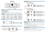
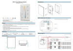
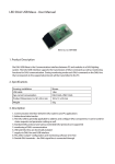
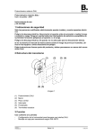
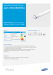
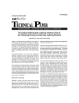
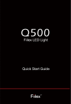
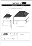
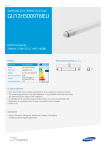
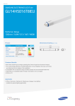
ПРОИЗВОДСТВО, ПОСТАВКИ СВЕТОДИОДОВ И СВЕТОДИОДНЫХ ИЗДЕЛИЙ
DALI Controller User Manual
DALI
Controller
User Manual
S
SR-2302B/ SR-2312B/ SR-2314B are 4-channel DALI dimmer with 1 address.
SR-2303B/ SR-2315B/ SR-2317B are 4-channel DALI dimmer with 4 addresses.
SR-2304B/ SR-2316B/ SR-2318B are 4-channel push-dim DALI dimmer with 1 address.
DALI controllers are compatible with all DALI system from OSRAM, TRIDONIC, HELVAR and so
on.
2.Parameter file
Part No.
Input
Voltage
Max load
current
Max Output
Power
Load Type
Remarks
SR-2302B
12-36VDC
4×5A
4×(60180)W
Regular LED
(0.04-0.1W)
1 DALI address
SR-2302BEA
12-36VDC
4×8A
4×(96288)W
Regular LED
(0.04-0.1W)
1 DALI address
SR-2312B
12-36VDC
4×0.350A
4×(4.2
-12.6)W
1 DALI address
SR-2314B
12-36VDC
4×0.70A
4×(8.4
-25.2)W
SR-2303B
12-36VDC
4×5A
4×(60180)W
SR-2303BEA
12-36VDC
4×8A
4×(96288)W
SR-2315B
12-36VDC
4×0.350A
4×(4.2
-12.6)W
SR-2317B
12-36VDC
4×0.70A
4×(8.4
-25.2)W
High
Power LED
(1W)
High
Power LED
(3W)
Regular
LED
(0.04-0.1W)
Regular
LED
(0.04-0.1W)
High
Power LED
(1W)
High
Power LED
(3W)
Regular
LED
(0.04-0.1W)
Regular
LED
(0.04-0.1W)
High
Power LED
(1W)
High
Power LED
(3W)
SR-2304B
12-36VDC
4×5A
4×(60180)W
SR-2304BEA
12-36VDC
4×8A
4×(96288)W
SR-2316B
12-36VDC
4×0.350A
4×(4.2
-12.6)W
SR-2318B
12-36VDC
4×0.70A
4×(8.4
-25.2)W
3.2
4.Wir
4.1
1 DALI address
4 DALI address
4 DALI address
4 DALI address
4 DALI address
4.2 S
1 DALI address
1 DALI address
1 DALI address
1 DALI address
3.Function and Wiring
3.1 DALI address can be automatically assigned by DALI master and also can be set manually.
DALI shows address via screen.
Set address automatically by DALI master.
Please follow DALI master user manual to assign address automatically.When DALI master
control DALI controller, it shows "AU" on screen.
www.optomleds.ru
Pres
sett
sett
flash
[email protected]
ПРОИЗВОДСТВО, ПОСТАВКИ СВЕТОДИОДОВ И СВЕТОДИОДНЫХ ИЗДЕЛИЙ
Set address manually
1
2
K1
K2
Press any key (K1 or K2) for over 3 seconds, then screen flashes which indicates the state of
setting address, then short press on the K1 or K2 button to set the address from “00” to “63” . After
setting the desired address, hold fingers on any key (K1 or K2) for over 3 seconds, screen stop
flashing which indicates the success of setting address.
3.2 Work with amplifier to expend power unlimitedly.
4.Wiring diagram
4.1 SR-2302B/ SR-2312B/ SR-2314B-ideal for single color LED lighting- 1 address
4.2 SR-2303B/ SR-2315B/ SR-2317B-ideal for RGB+W LED lighting- 4 addresses
R
R
G
G
B
B
Y
Y
SR-2303B
www.optomleds.ru
[email protected]
ПРОИЗВОДСТВО, ПОСТАВКИ СВЕТОДИОДОВ И СВЕТОДИОДНЫХ ИЗДЕЛИЙ
4.3 SR-2304B/ SR-2316B/ SR-2318B-ideal for single color LED lighting ( control by DALI
system & push dim button)
SR-2304B
1.Operatio
Under this
with DALI
2. Operati
Under this
independe
another D
Press swi
the lightin
After ente
3. Switchi
Either the
240VAC) s
Under DA
signal. Un
it shows th
address w
www.optomleds.ru
[email protected]
ПРОИЗВОДСТВО, ПОСТАВКИ СВЕТОДИОДОВ И СВЕТОДИОДНЫХ ИЗДЕЛИЙ
1.Operation under DALI dimming mode
Under this mode, DALI device is just a standard DALI dimmer, it can connect DALI master signal
with DALI signal input port. Dimming lightings are operated by DALI master.
2. Operation as 1-Button push dimmer
Under this mode, DALI device can be isolated from DALI system. It can operate as an
independent dimming controller. Through a switch, L-LINE of AC (200-240 VAC) can connect with
another DALI input port. Press switch less than 0.5 seconds, it can switch ON/OFF of lightings.
Press switch over 1.5 seconds, it can do dimming operation. First press switch over 1.5 seconds,
the lightings will be brighter. Then press switch over 1.5 seconds, the lightings will be darker.
After entering to this mode, the screen shows “PD” – “PUSH DIMMER” mode.
3. Switching of 2 modes
Either the DALI dimmer wiring with DALI signal input or PUSH DIMMER wiring with AC (200240VAC) signal, DALI input port must be unique. It's unable to access 2 signals at the same time.
Under DALI dimmer mode, DALI device enters into PUSH DIMMER mode with AC (200-240VAC)
signal. Under PUSH DIMMER mode, device enters into DALI dimmer mode with DALI signal. And
it shows the previous set address. Within back and forth switching modes process, the DALI
address won't be lost or changed.
www.optomleds.ru
[email protected]