1
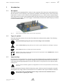
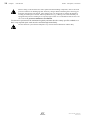
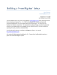
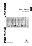
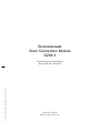
Sirenenzusatz
Siren Connection Module
SZ58-3
© by Labor Strauss Sicherungsanlagenbau Ges.m.b.H. Wien
Beschreibung und Anschaltung
Description and Connection
Änderungen vorbehalten
Subject to change without notice
Alle Teile dieses Handbuches sowie der Gerätesoftware unterliegen dem Urheberrecht. Kein Teil dieses Handbuches oder der Gerätesoftware darf ohne schriftliche Genehmigung von Labor Strauss Sicherungsanlagenbau Ges.m.b.H. Wien in irgend einer Form vervielfältigt,
verbreitet, kopiert, fototechnisch übertragen, reproduziert, übersetzt oder auf einem anderen elektronischen Medium gespeichert werden
oder in maschinell lesbare Form gebracht werden.
Die in diesem Handbuch enthaltenen Angaben wurden mit größter Sorgfalt erarbeitet. Für eventuell verbliebene fehlerhafte Angaben und
deren Folgen werden jedoch weder eine juristische Verantwortung noch irgend eine Haftung übernommen. Labor Strauss Sicherungsanlagenbau Ges.m.b.H. Wien behält sich vor, Angaben ohne vorherige Ankündigung zu ändern und geht damit keinerlei Verpflichtungen
ein. Für die Mitteilung eventueller Fehler im Handbuch sind die Autoren jederzeit dankbar.
Die in diesem Handbuch erwähnten Soft- und Hardwarebezeichnungen können auch dann eingetragene Warenzeichen sein, wenn darauf
nicht besonders hingewiesen wird. Sie gehören den jeweiligen Warenzeicheninhabern und unterliegen gesetzlichen Bestimmungen.
All parts of this User Manual as well as the software are subject to copyright law. No part of this manual or of the software may be multiplied, disseminated, copied, transferred by phototechnical means, reproduced, translated, or saved to any electronic medium or in machinereadable form, in any way, shape or form, without the prior written consent of Labor Strauss Sicherungsanlagenbau Ges.m.b.H. Wien.
The information contained in this User Manual has been elaborated with the highest degree of care. No legal responsibility or any other
kind of liability will be accepted for incorrect information that may remain in the document nor for any consequences therefrom. Labor
Strauss Sicherungsanlagenbau Ges.m.b.H. Wien reserves the right to change information without notice and accepts no liability therefor.
The authors kindly request that any errors appearing in the User Manual be brought to their attention.
All names of software and hardware used in this Manual may even then be registered trademarks if it is not explicitly indicated. These
trademarks belong to their respective owners and are subject to legal requirements.
3
SZ58-3 Beschreibung, Anschaltung
Inhaltsverzeichnis
1
1.1
1.2
1.3
Einleitung..........................................................................................................................5
Beschreibung...................................................................................................................5
Darstellungsarten.............................................................................................................5
Wichtige Hinweise..........................................................................................................5
2
Montage.............................................................................................................................7
3
3.1
3.2
3.3
3.4
3.4.1
3.4.2
Anschaltung......................................................................................................................8
Stromversorgung.............................................................................................................8
Sirenenkreise.................................................................................................................10
Aktivierung der Sirenenkreise.......................................................................................11
Störmeldeausgänge........................................................................................................12
Anschaltung der Störmeldeausgänge an Gruppenplätze für Grenzwertmelder..........12
Anschaltung der Störmeldeausgänge an Steuereingänge............................................13
4
Technische Daten...........................................................................................................15
Contents
1
1.1
1.2
1.3
Introduction....................................................................................................................17
Description.....................................................................................................................17
Types of symbols...........................................................................................................17
Important tips.................................................................................................................17
2
Installation......................................................................................................................19
3
3.1
3.2
3.3
3.4
3.4.1
3.4.2
Connection......................................................................................................................20
Power supply.................................................................................................................20
Siren circuits..................................................................................................................22
Activation of the siren circuits.......................................................................................23
Fault detection outputs...................................................................................................24
Connection of the fault detection outputs to zone ports for conventional detectors...24
Connection of the fault detection outputs to actuation inputs.....................................25
4
Specifications..................................................................................................................27
SZ58-3.odt / 0602 / AN9161251
ZN5375/27/3
B
SZ58-3 Description, Connection
1
Introduction
1.1
Description
Chapter 1 • Introduction
17
The Siren Connection Module SZ58-3 allows for the expansion of fire detection control panels Series
BC216, BC016 as well as BC06 by four separately actuatable, individually fused as well as line-monitored electric circuits, to each of which several signaling devices (e.g., sirens) can be connected in parallel. These electric circuits can be supplied either from the fire detection control panel itself or from an
external 24V power supply. The sirens supply is automatically monitored for undervoltage by the Siren
Connection Module SZ58-3.
SZ58-3_Sc hem a.c dr / SZ58-3
Fig. 1:
1.2
Siren Connection Module SZ58-3 View of the componentry
Types of symbols
Especially important sections of text in this User Manual are indicated with symbols. The following
symbols are used:
Means DANGER! Ignoring these tips can result in danger to life and health.
Means ATTENTION! Ignoring these tips can result in system malfunctions or damage to property.
Means TIP! Here the text contains tips for easier operation.
UNG
ZULASS
1.3
Means that the country-specific and/or the site-specific requirements of the APPROVALS of the fire
detection system must be observed.
Important tips
Fire detection systems and devices, respectively, must be installed strictly by qualified personnel that is
being trained on a regular basis. The specific training of the qualified personnel must be provided by
Labor Strauss Sicherungsanlagenbau Ges.m.b.H. Wien (LST) or by persons who are expressly authorized by LST.
Country-specific standards, regulations, and guidelines as well as LST specifications must be strictly
observed.
To ensure the flawless function of the fire detection system, all devices must be mounted as intended
and supplied with voltage. Make sure that all devices are suitable for the expected ambient conditions.
All work may only be conducted when the voltage is shut down. The installation must be
checked prior to applying the voltage.
SZ58-3.odt / 0602 / AN9161251
ZN5375/27/17
B
18
Chapter 1 • Introduction
SZ58-3 Description, Connection
When working on the fire detection control panel and when handling components, observe the usual
protective measures for discharging static electricity charges: Before and during the work being performed on the printed circuit boards, static charges from your body must be reliably discharged by
touching an earthed piece of metal. Mains-operated tools (e.g., soldering irons) must absolutely be
equipped with protective earthing or be expressly approved for use on installations that are static-sensitive. The usual protective insulation is not sufficient.
Fire detection systems must be maintained regularly and must take the country-specific standards as a
basis. Any required repair work must be carried through immediately.
The fire detection system must be adapted to any constructional modification without delay.
B
SZ58-3.odt / 0602 / AN9161251
ZN5375/27/18
SZ58-3 Description, Connection
2
Chapter 2 • Installation
19
Installation
The Siren Connection Module SZ58-3 by means of the screws and metal bolts from the enclosed packet
of assembly material is mounted to an earthed metal mounting surface which provides mounting holes
in LST standard grid (see Fig. 2). Preferably mount the Siren Connection Module SZ58-3 on a mounting bracket within the housing of the fire detection control panel.
Be sure to establish a secure earth connection between the componentry and the earthed mounting surface via the four metal bolts – only then is the componentry as well as the entire fire detection control
panel effectively protected against EMC effects.
98
24V 24V
Activation siren circuit 2
Activation siren circuit 3
Activation siren circuit 4
Fault detec. outp. siren circ. 1
Fault detec. outp. siren circ. 2
Fault detec. outp. siren circ. 3
Fault detec. outp. siren circ. 4
Supply voltage
Siren circuits
Activation siren circuit 1
Operating voltage
SZ58-3
75
4ø
1 2 3 4 5 6 7 8 9 10 11 12
SZ58-3
1
2
3
74
61
JP2
JP3
JP1
ST2
1
2
3
1
2
3
JP4
1
2
3
ST1
Siren circuit active (red)
1
2
3
4
Siren circuit faulty
(yellow)
13 14 15 16 17 18 19 20
SZ58-3_Schema.cdr / Montage
Fig. 2:
Siren circuit 4
Siren circuit 3
Siren circuit 2
Siren circuit 1
Dimensions and position of the terminals, jumpers, connector slots and display elements of the Siren
Connection Module SZ58-3
If possible, mount the Siren Connection Module SZ58-3 inside the housing of the fire detection control panel that also provides the operating voltage of the siren connection module (see directions on
page 20 an on in Chapter 3.1: "Power supply").
SZ58-3.odt / 0602 / AN9161251
ZN5375/27/19
B
20
3
Chapter 3 • Connection
SZ58-3 Description, Connection
Connection
The Siren Connection Module SZ58-3 provides four separately actuatable, individually fused as well as
line-monitored electric circuits, to each of which several signaling devices (e.g., sirens) can be connected in parallel. These electric circuits can be supplied either from the fire detection control panel itself or from an external 24V power unit. The sirens supply is automatically monitored for undervoltage
by the Siren Connection Module SZ58-3.
The figure below shows power connection, input and output signals as well as the internal circuit of the
Siren Connection Module SZ58-3 in a simplified way.
Siren Connection
Module SZ58-3
+24V
1
2
+24V
3
4
1N4004
green
blue
red
UB+
Si1
13
AE+
4x100k
IN1
5
IN2
6
IN3
7
IN4
8
5.6k
+
Siren
circuit 1
+
Rab
5.6k
-
-
4x
14
AE+
Si2
15
10
Siren circuit 2
16
1
ST2
AE+
Si3
17
10
Siren circuit 3
18
1
ST1
9
10
11
12
SZ58-3_Schema.cdr / Anschluss
Fig. 3:
3.1
OUT1
UB+ AE+
47k
1 JP1
2
3
OUT2
1
2 JP2
OUT4
1
1
2 JP3
3
19
Siren circuit 4
20
47 5,6k
= Siren circuit active (red)
3
OUT3
Si4
4x
= Siren circuit faulty (yellow)
2 JP4
3
10-pole flat cable for the connection of an additional
Siren Connection Module SZ58-3 or Relay Module RL58-1, RL58-2
Overview of the input and output signals of the Siren Connection Module SZ58-3
The individual siren circuits are activated when ground (-) is applied to the respective inputs IN1 ...
IN4 or to the corresponding flat cables. Faults of the siren circuits are reportet to the fire detection
control panel via outputs OUT1 ... OUT4.
Power supply
The operating voltage of the control and monitoring devices on the Siren Connection Module SZ58-3 is
in most cases provided by the fire detection control panel, the sirens supply can – depending on the demand of power – either also be provided by the fire detection control panel or by a separate 24V power
unit.
The control and monitoring devices of the Siren Connection Module SZ58-3 (terminals 1 and 2) must
be supplied with power from the same fire detection control panel to which the fault detection outputs
of the Siren Connection Module SZ58-3 are connected (see page 24 and on in Chapter 3.4: "Fault detection outputs").
B
SZ58-3.odt / 0602 / AN9161251
ZN5375/27/20
SZ58-3 Description, Connection
Chapter 3 • Connection
21
If you want to use a separate power unit for the sirens supply, you must keep in mind that the negative
connections of the two supply voltages (terminals 2 and 4) are electrically connected with each other
on the Siren Connection Module SZ58-3! This way, the entire line system that is connected to the 24V
output voltage of this power unit is automatically included in the earth fault monitoring of the fire detection control panel.
Undervoltage (see page 27 an on in Chapter 4: "Specifications") or failure of the sirens supply (terminals 3 and 4) is reported as fault on all four fault detection outputs in parallel.
A breakdown of the operating voltage (terminals 1 and 2) cannot be reported by the Siren Connection
Module SZ58-3. Therefore connect terminals 1 and 2 of the Siren Connection Module SZ58-3 only to
a voltage output of the fire detection control panel which can have its failure (e.g., initiated by a fuse
failure) detected and reported as fault by the fire detection control panel.
The permissible range of the output voltage of the additional power supply for the supply of the siren
circuits that is specified in the Specifications (see page 27 an on in Chapter 4: "Specifications") must
be strictly observed. If the lower limit value is under-run, a fault of all siren circuits is displayed, if the
upper limit value is exceeded, the Siren Connection Module SZ58-3 and hence also the fire detection
control panel can be damaged!
Fire detection control
panel
+24V
Siren Connection
Module SZ58-3
+24V
+
-
UB+
1
2
Additional power supply
+24V
+24V
+
-
3
4
AE+
SZ58-3_Sc hem a.c dr / Spg_v ers_getrennt
Fig. 4:
Power supply of the Siren Connection Module SZ58-3 from the fire detection control panel and an
additional power unit
The operating voltage of the SZ58-3 is provided by the fire detection control panel, the sirens are
supplied by an additional high-capacity power unit.
Please note that the negative connections (terminals 2 and 4) on the Siren Connection Module
SZ58-3 are electrically connected with each other (also see directions above)!
The additional power unit for the supply of the sirens must – as illustrated in the figure – absolutely
be connected to terminals 3 (+24V) and 4 (-).
Siren Connection
Module SZ58-3
Fire detection control
panel
+24V
UB+
1
2
+
-
+24V
3
4
AE+
SZ58-3_Sc hem a.c dr / Spg_v ers_gemeinsam
Fig. 5:
Power supply of the Siren Connection Module SZ58-3 from the power unit of the fire detection control panel
Both the operating voltage of the SZ58-3 and the sirens supply are provided by the fire detection control panel.
Due to the possible high current consumption of the siren circuits, the cabling must be realized as illustrated in Fig. 5, i.e. the voltage must be connected to terminals 3 (+) and 4 (-) and terminals 1 and 3
must be connected with each other.
SZ58-3.odt / 0602 / AN9161251
ZN5375/27/21
B
22
Chapter 3 • Connection
SZ58-3 Description, Connection
The power unit that caters for the sirens supply in addition to the maximum possible total current of
all alarming devices connected to siren circuits 1 - 4 must have a sufficient power reserve. This power
reserve must be calculated in a way that on a short circuit of a siren circuit and simultaneous activation of the other siren circuits, the required total current can be provided without nameable voltage
drops (see switching threshold undervoltage siren circuit on page 27 in Chapter 4: "Specifications").
The siren circuits of the SZ58-3 itself are protected through self-healing electronic fuses.
When the short circuit is removed from the siren circuit, the output is fully functional again.
3.2
Siren circuits
Four independent siren circuits for the line-monitored actuation of acoustic or optical signaling devices
(sirens, strobes, etc.) are located on the Siren Connection Module SZ58-3. The outputs for the siren circuits are effectively protected against EMC effects. The appropriate regulations for electrical engineering must be observed when conducting cabling work.
For reasons of clarity, the components of EMC protective circuits of the outputs that are located on the
componentries have been omitted in the following connection diagram.
SZ58-3
1N4004
5.6k
UB+
green
blue
red
1
2
+24V
+
-
+24V
AE+
Si1
3
4
13
+
Siren
circuit 1
-
+
Rab
5.6k
-
4x
14
Si2
15
Siren circuit 2
Siren circuit active (red)
16
Si3
17
Siren circuit 3
Siren circuit faulty (yellow)
18
Si4
19
Siren circuit 4
20
SZ58-3_Schema.cdr / Sirenenkreise
Fig. 6:
Connection of the signaling devices to the siren outputs
For each siren circuit two LEDs are designated for the display of the conditions 'Siren circuit active'
(red illuminated) and 'Siren circuit faulty' (yellow illuminated).
The siren circuits are protected through self-healing electronic fuses Si1 ... Si4. When the short circuit is removed from the siren circuit, the output is fully functional again.
Siren circuit 1 is activated through input IN1 (terminal 5, see Fig. 7), siren circuit 2 is activated
through input IN2, etc.
Line monitoring is accomplished through a negative surveillance voltage (approx. -1.2V at 5.6kΩ endof-line resistance) that is applied to terminals 13, 15, 17, and 19 in normal condition. The serial diodes
of the signaling devices shown in Fig. 6 block this negative voltage for each signaling device. In the
event of activation, the sirens supply less 1V is output current-limited (see page 27 in Chapter 4: "Specifications") and short-circuit-proof on terminals 13, 15, 17, and 19.
The maximum current consumption of all devices must not exceed 0.5A per siren circuit.
The total current consumption of all signaling devices connected to the SZ58-3 may amount to 2A at
most. Also note the directions concerning the capacity of the power unit on page 20 and on in Chapter
3.1: "Power supply".
B
SZ58-3.odt / 0602 / AN9161251
ZN5375/27/22
SZ58-3 Description, Connection
Chapter 3 • Connection
23
If the electronic fuse responded due to an overload of the siren circuit, it is recommended that you
switch off the siren circuit for several seconds after the cause of the error has been removed.
If several signaling devices are to be operated monitored on one siren output, they must be connected
in a chain as illustrated in Fig. 6. With star-shaped cabling, the display of a line interruption is only
possible for the part of the line that has the end-of-line resistor connected on its end.
If no signaling device is connected to a siren output, both terminals of the output must be terminated
with a 5.6kΩ end-of-line resistor instead to prevent the fault detection output and the yellow LED 'Siren
circuit faulty' from indicating a fault.
5.6kΩ end-of-line resistors are included in the enclosed packet of assembly material of the componentry.
3.3
Activation of the siren circuits
A siren circuit is activated when ground (-) is applied to the respective activation input IN1 ... IN4 (terminals 5 ... 8) or to the corresponding connection pin of the flat cable connector ST1 of the Siren Connection Module SZ58-3. Each of the four siren circuits can be activated individually.
UB+
4x100k
1)
100
2)
IN1
5
IN2
6
IN3
7
IN4
8
10
3)
10
1
ST2
10
1
1
ST1
SZ58-3_Schema.cdr / Aktivierung
1)
2)
3)
Fig. 7:
10-pole flat cable for the connection of an additional
Siren Connection Module SZ58-3 or Relay Module RL58-1, RL58-2
Activation of siren circuit 1 via a contact connected to ground (-).
Activation of siren circuit 4 via an open collector output (e.g., FWI2-1, FWI016-1).
Activation of siren circuits 1 through 4 via the open collector auxiliary outputs of the fire detection control
panel. Depending on the version of the fire detection control panel, the control and monitoring devices of the
SZ58-3 can also be supplied with power via the flat cable. The power supply of the siren circuits, however,
must always take place on terminals 3 and 4 of the Siren Connection Module SZ58-3!
Via the flat cable connector ST2, you can further connect the open collector auxiliary outputs 5 through 8 to
different componentries (e.g., to an additional Siren Connection Module SZ58-3 or to Relay Modules
RL58-1 or RL58-2).
Connection to the activation inputs of the siren circuits
The activation signal (-) on input IN1 acts on siren circuit 1, IN2 acts on siren circuit 2, etc.
As long as a siren circuit is activated, the corresponding LED 'Siren circuit active' is illuminated.
The terminal of the activation input is electrically connected with the corresponding connection of the
flat cable connector on the componentry. An activation signal that is applied to the flat cable connector is also available on the corresponding terminal and vice versa.
If required, you can also connect two signals in parallel (i.e. one signal via the flat cable and one signal via the activation input) for one siren circuit.
The Siren Connection Module SZ58-3 does not distinguish between activation signals applied to the
terminal and those applied to the corresponding connection of the flat cable connector.
If several siren circuits are to be activated by the same input signal, you must connect the respective
activation inputs with each other and actuate them jointly.
SZ58-3.odt / 0602 / AN9161251
ZN5375/27/23
B
24
Chapter 3 • Connection
SZ58-3 Description, Connection
The cables connected to the terminals of the activation inputs may only then leave the interior of the
housing of the fire detection control panel or an auxiliary case mounted in the immediate vicinity of
the control panel housing if no open collector auxiliary output of the fire detection control panel is
connected to the flat cable connector ST1.
Furthermore, please note that although the activation inputs are indeed sufficiently protected against
EMC effects, due to the high input resistance, however, an influence of power lines running in parallel
to activation lines outside the control panel housing cannot entirely be ruled out.
3.4
Fault detection outputs
The fault detection outputs report a detected wire breakage or a short circuit in the line system of the
corresponding siren circuits. In addition, on undervoltage or failure of the sirens supply connected to
terminals 3 and 4 of the SZ58-3 (see page 27 in Chapter 4: "Specifications"), a fault of the siren circuits
is indicated simultaneously on all four fault detection outputs.
To indicate a fault, the fault detection outputs can be connected
to zone ports for conventional detectors (fire detection control panels Series BC216, BC016, or
BC06, respectively) which are parameterized, for example, as fault detection zones, or
to actuation inputs (fire detection control panels Series BC216 or BC016, respectively).
As long as a fault is indicated, the corresponding yellow LED 'Siren circuit faulty' on the siren connection module is illuminated.
3.4.1
Connection of the fault detection outputs to zone ports for conventional detectors
In normal condition, the respective zone port of the fire detection control panel is terminated with an
end-of-line resistor (5.6kΩ) located on the Siren Connection Module SZ58-3. In the event of a fault
(e.g., on line failure of a siren circuit), the SZ58-3 applies the short-circuit criterion to the respective
zone port and thus displays a fault on the fire detection control panel.
You can connect the fault detection outputs of as much siren circuits with each other as you like – also
from several siren connection modules – and jointly connect them to a zone port for conventional detectors. You can tell from the respective illuminated yellow LED of the Siren Connection Module SZ58-3
which of the siren circuits is faulty.
Fault detection outputs of different Siren Connection Modules SZ58-3 may only then be combined if
all concerned siren connection modules are connected to the same operating voltage.
The cables connected to the fault detection outputs must under no circumstances leave the interior of
the housing of the fire detection control panel or an auxiliary case mounted in the immediate vicinity
of the control panel housing!
You must not connect fault detectors or fire detectors to a zone port which is used for displaying
faults of a siren connection module! The fault message of the siren connection module prevents
any messages from additionally connected detectors!
B
SZ58-3.odt / 0602 / AN9161251
ZN5375/27/24
SZ58-3 Description, Connection
Chapter 3 • Connection
SZ58-3
1
Zone port
La
Lb
1)
9
OUT1 2
Zone port
Lb
UB+
JP1
3
47k
1
La
10
2)
OUT2 2
3
1
OUT3 2
1
OUT4 2
47
5.6k
47
5.6k
47
5.6k
JP3
3
47k
12
47 5.6k
JP2
47k
11
25
JP4
3
47k
SZ58-3_Schema.cdr / RM_GW_Gruppe
1)
2)
Fig. 8:
Fault message of a single siren circuit to a zone port.
Connect contact pins 1 and 2 of the corresponding jumper (JP) by means of a shorting plug.
Fault message of several siren circuits to a zone port.
Only at the last fault detection output connect contact pins 1 and 2 of the corresponding jumper (JP) by
means of a shorting plug, at all the remaining jumpers whose outputs form the joint message line, the contact
pins must not be connected.
If required, the joint message line can lead through several siren connection modules which must all be connected to the same operating voltage.
Connection of the fault detection outputs to zone ports for conventional detectors
In the event of a line failure of a siren circuit, the SZ58-3 applies the short-circuit criterion to the respective zone port and thus displays a fault on the fire detection control panel.
The fault signal on output OUT1 (terminal 9) indicates the fault of siren circuit 1, OUT 2 (terminal 10) indicates the fault of siren circuit 2, etc.
Fault detection outputs may only be connected to zone ports in the very fire detection control panel
that also provides the operating voltage for the SZ58-3 (terminals 1 and 2).
Plug the shorting plugs that are not required into a single contact pin of the respective jumper (without
connecting the contact pins) – this way the shorting plugs are available for possible later use.
The zone ports of the fire detection control panel must be set to end-of-line resistors of 5.6kΩ.
3.4.2
Connection of the fault detection outputs to actuation inputs
The fault detection outputs of the Siren Connection Module SZ58-3 can be connected to all actuation
inputs of fire detection control panels Series BC216 as well as BC016. This applies both to the actuation inputs on the individual central processing boards and to the inputs on the fire brigade interfaces.
You can also connect the fault detection outputs of as much siren circuits with each other as you like –
also from several Siren Connection Modules SZ58-3 – and jointly connect them to an actuation input.
You can tell from the respective illuminated yellow LED(s) of the Siren Connection Module SZ58-3
which of the siren circuits is faulty.
Fault detection outputs of different Siren Connection Modules SZ58-3 may only then be combined if
all concerned siren connection modules are connected to the same operating voltage.
The cables connected to the fault detection outputs must under no circumstances leave the interior of
the housing of the fire detection control panel or an auxiliary case mounted in the immediate vicinity
of the control panel housing!
SZ58-3.odt / 0602 / AN9161251
ZN5375/27/25
B
26
Chapter 3 • Connection
SZ58-3 Description, Connection
SZ58-3
47k
100k
1
1)
9
OUT1 2
47k
1
2)
JP1
3
10k
47k
100k
UB+
10
OUT2 2
47k
1
11
OUT3 2
1
3)
12
OUT4 2
47k
RM1
1
2
3
47
5.6k
47
5.6k
47
5.6k
UB+
SZ58-3
9
5.6k
JP4
3
10k
47
JP3
3
47k
47k
5.6k
JP2
3
10k
47
JP1
47k
SZ58-3_Schema.cdr / RM_Eingang
1)
2)
3)
Fig. 9:
Fault message of a single siren circuit to an input that can be activated by applying ground.
Contact pins 1, 2, and 3 on the jumper (JP) remain open (are not connected).
The input must be parameterized as "NO-contact" on the fire detection control panel.
Fault message of several siren circuits to an input that can be activated by applying ground.
Contact pins 1, 2, and 3 on the jumpers (JP) remain open (are not connected) at all fault detection outputs of
this joint message line.
If required, the joint message line can lead through several Siren Connection Modules SZ58-3 which must
all be connected to the same power supply.
This input must be parameterized as "NO-contact" on the fire detection control panel.
Fault message of one or several siren circuits to an input that can be activated by applying a positive voltage.
Only at the last (or only, respectively) fault detection output of this joint message line connect contact pins 2
and 3 of the corresponding jumper (JP) by means of a shorting plug, at all the remaining jumpers whose output form the joint message line, the contacts must not be connected.
If required, the joint message line can lead through several Siren Connection Modules SZ58-3 which must
all be connected to the same power supply.
This input must be parameterized as "NC-contact" on the fire detection control panel.
Connection of the fault detection outputs to actuation inputs of the central processing boards or fire
brigade interfaces of fire detection control panels Series BC216 or BC016
In the event of a line failure of a siren circuit, the SZ58-3 applies ground (-) to the respective actuation input and thus displays a fault on the fire detection control panel.
The fault signal on output OUT1 (terminal 9) indicates the fault of siren circuit 1, OUT 2 (terminal 10) indicates the fault of siren circuit 2, etc.
Fault detection outputs may only be connected to inputs in the very fire detection control panel which
also provides the operating voltage for the SZ58-3 (terminals 1 and 2).
Plug the shorting plugs that are not required into a single contact pin of the respective jumper (without
connecting the contacts) – this way the shorting plugs are available for possible later use.
B
SZ58-3.odt / 0602 / AN9161251
ZN5375/27/26
SZ58-3 Description, Connection
4
Chapter 4 • Specifications
Specifications
Operating voltage (terminals 1 and 2)
Sirens supply (terminals 3 and 4)
Switching threshold undervoltage siren circuit
Current consumption at 24V (terminals 1 and 2)
Siren circuits
Number
Permissible load current of each siren circuit
Current limitation of each siren circuit
Output voltage quiescent
Output voltage activated
End-of-line resistor
4
max. 0.5A permanently
0.7 ... 2.1A
typ. -1.2V (at Rab 5.6kΩ)
sirens supply less typ. 1V
5.6kΩ
Dimensions L × W × H
Weight
Ambient temperature
98 × 74 × 18 (mm)
60g
-5°C to +50°C
SZ58-3.odt / 0602 / AN9161251
ZN5375/27/27
B
21 to 30VDC
21 to 30VDC
typ. 20.7V
typ. 15mA (all 4 siren circuits quiescent)
27