1
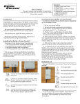
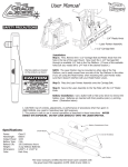
In addition to the hardware kit that you received
with the QBOT, you will need the hardware
in this kit to complete the installation on your
frame.
The hardware kit for the Grace Little Gracie II
includes:
(3)
(2)
(2)
(1)
(1)
(3)
(3)
(1)
(1)
(1)
¼ x 2” screws
Aluminum spacers
Special Y-Axis Brackets
X-axis drive wire 74” length
X-axis drive wire 102.5” length
¼ X 1” screw
¼” nut
¼” fender washer
X-Axis Link
Y-Axis Link
LITTLE GRACIE II
INSTALLING THE DRIVE SYSTEM
Remove the lower left screw from the back
of the lower carriage and set aside for use
later. Using one ¼ X 2” long screw and one
aluminum spacer, connect the left hand side
of the drive bracket to the back of the lower
carriage as shown in Figure 1. Next, remove
the screw from the lower right of the lower
carriage and insert the X-Axis Link as shown in
Figure 2. Using the screw that you removed
earlier, attach the right hand side of the drive
assembly to the other side of the link using a
washer from the hardware kit that came with
your QBOT and ¼” nut as shown in the picture.
Nut (not visible)
X-Axis Link
Washer
Screw
Figure 1.
Figure 2.
LITTLE GRACIE II
INSTALLING THE DRIVE SYSTEM
Install the two special Y-Axis brackets that came with
this hardware kit on the lower carriage as shown. The
bracket labeled with an ‘L’ mounts to the rear left-hand
side of the lower carriage. The bracket labeled with
an ‘R’ mounts to the front right hand side of the lower
carriage. Simply loosen the screw on the carriage
and slip the bracket under the head of the screw. It is
important that they are attached at the angle shown in
the pictures. This will ensure that the drive wire will be
installed level.
The front attachment looks like the picture
to the left. The drive wire is shown installed
and the tensioner has been adjusted to
the correct tension using the tensioning
template found at the back of your QBOT
manual.
Aluminum spacer
Using the remaining ¼ X 2” screws, one aluminum
spacer, one ¼ X 1” screw and nut, and the Y-Axis
Link, attach a drive bracket to the upper carriage as
shown in the picture to the right. Note the location
of the aluminum spacer and Y-Axis Link. Tighten the
screws securely.
You will install the drive wire in the next step.
Nut (not visible)
LITTLE GRACIE II
INSTALLING THE DRIVE SYSTEM
The Y-Axis drive wire that came with the QBOT (24”
length) is installed by hooking one end of the wire to the
rear wire bracket and winding twice (2X) around the drive
wheel. Looking at the picture to the right, note how the
drive wire is wrapped around the wheel so that it is on the
bottom side of the drive wheel. Wrapping the wire the
wrong way (off the top side) will cause the carriage to go
backwards.
Hook the eyelet at the other end of the wire on one side
of the tensioner as shown in the picture below. Hook the
other end to bracket as shown and tighten the tensioner
until the tension in the wire falls in the proper range
shown on the tensioning template. See page 5 of the User
Manual for reference.
Note: Drive wire enters and
exits from the bottom of the
drive wheel.
LITTLE GRACIE II
INSTALLING THE DRIVE SYSTEM
Attach the X-axis brackets that came with
your QBOT to your frame on either end
as shown in the photos to the right. Note
the orientation of the brackets. Simply
loosen the screws on the back of the
frame and slide the bracket underneath
the head of the screw. Tighten securely.
View looking down on the X-Axis drive wheel
from back of carriages.
Note that the wire enters and exits from the top
of the drive wheel.
Crib: Wrap 4X, Queen: Wrap 2X
Bottom edge level
Attach one end of the drive wire to the X-axis
bracket as shown in the top photo. Wrap the wire
around the drive wheel four times (4X) if you are
setting up the frame at the Crib length or twice
(2X) if you are setting up your frame at the Queen
length. Ensure that you start at the TOP of the
wheel as shown in the photo to the left. Attach the
other end of the wire to the tensioner as shown in
the photo above. Finally attach the other end of
the tensioner to the X-axis bracket as shown above.
Use the tensioning template in the back of the User
Manual to set the proper tension in the wire.
Using the ¼-20 X 1” screw, nut, and fender washer, attach the QBOT mounting bracket to the upper carriage handle assembly. Tighten securely.
Congratulations!
You are now ready to make the connections. Follow the instructions in your User Manual starting
on page 15.
LITTLE GRACIE II
INSTALLING THE DRIVE SYSTEM