1
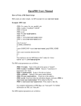
AFP ELAVATOR EC10-D - Installation Guide EC10-D DIGITAL DOOR CONTROLLER "User manual" Version: B4.85 Software: AFP 15 Manufacture by: AFP ELEVATOR Co. www.afpelevator.com 1 AFP ELAVATOR EC10-D - Installation Guide 2 AFP ELAVATOR EC10-D - Installation Guide Contents: Page Number ::::: Overview Chapter 1: A) Introduction: 1- Accessories…………………………………. ………………………….……... 8 2- Dimension……….............................................................................. 9 3- Installing suggestion…….……………….…………………………….....… 10 4- Door suspension…………………………………………………………….... 10 5- The output & input terminals……………………………………………… 11 13 6-Wiring plan…………………………………………………………………….. Chapter 2: C) Initializing System: 1-Introducing the panel parts………..……………………….….………….…. 17 2- Setting and programming………………………….……….………….….... 18 3- Selecting the door type……………………………………………………… 19 Chapter 3: D) The Professional Setting: 1- The professional system…………………………………….……….……..… 25 2- Traveling time definitions………………………….…………..................... 27 3- Protection against sensors damage…………………………………………. 29 Chapter 4: 33 E) Trouble Shooting: Chapter 5: F) Attachments: 1- How To change the drive type?……………………………………………………. 37 2- The Parameter Difference in Different Situations…………………………. 38 3- Indicator message……………………………………………………………... 39 3 AFP ELAVATOR EC10-D - Installation Guide 4 AFP ELAVATOR EC10-D - Installation Guide :: Over view Digital Door Controller EC – 10D Features: • Designed for soft movement for different cabin doors • Digital control & programming for desired movement ability • Powerful software to control system in closing and opening cycle independent of each other • Encoder optional controlling • Designed for controlling DC motors ( 24v – 3A) • Four segment, panel – mountable LED display / keypad • Ability to regulate all movement parameters through a keypad Containing timing, fluxes, speeds (max, min, acceleration, deceleration curves) • With Various safety system (reversing system, nudging...)and failures(high voltage, thermal protection and signal failure) • Protection against output short-circuit 5 AFP ELAVATOR EC10-D - Installation Guide Congratulations for choosing this door controller. This system is designed for the best possible function. Therefore, it has both intelligent controller system and full software setting. According to full wave system use all decelerations and accelerations in all movements can be separately controlled. It is to be said that this drive is setted by door default parameters while testing in the factory. By reading this Manuel, before install and use, learn more about its abilities. 6 AFP ELAVATOR EC10-D - Installation Guide Introduction Chapter1 7 1 AFP ELAVATOR EC10-D - Installation Guide 1- Accessories: 1- Four magnet switches with wire 2- Two magnets 3- Screw driver 4- Installation guide 5- Three terminals 6- Seven screws 8 AFP ELAVATOR EC10-D - Installation Guide 2- Dimension: 9 AFP ELAVATOR EC10-D - Installation Guide 3- Installation Suggestion: CLL2 and OPL2 sensors install point is where the door is at the end of its movement (both opening and closing). Incorrect install of sensors causes wrong function. • Neither make sure that magnet distance from magnet switch is correct not too far nor too close (about 2 cm is fine). • Magnet switches are NO (Normally Open) type. 4- Door suspension: MAGNET SWITCHES 30 CM OPL2 OPL1 30 CM CLL1 CLL2 MAGNET 1KT Open close 10 AFP ELAVATOR EC10-D - Installation Guide 5- The output & input terminals: Terminal Terminal Input Number Name Output Description LEDs situation Output Relay Overload close contact 1,2 OVL Output relay (while closing if a passenger is in Off the door way the door won't close). Open door command input which is not 3 OPEN Input activated in this version (this port gets Off its commands from elevator controller). Close door command input (this port 4 CLOSE Input gets its commands from elevator Off controller). ____ Open & close terminals common _ terminal 5 COM 6 OPL1 Input 7 OPL2 Input 8 COM 9 CLL1 Input 10 CLL2 Input ___ First open sensor feedback(this sensor Normally decreases speed) open Second open terminal feedback(this Normally sensor stops door movement) open ____ OPL1 & OPL2 terminals common _ terminal ___ First close sensor feedback(this sensor Normally decreases speed) open Second close terminal feedback(this Normally sensor stops door movement) open 11 AFP ELAVATOR EC10-D - Installation Guide ____ CLL1 & CLL2 terminals common _ terminal 24 AC Input Circuit supply voltage MOTOR Output Output terminals to motor 11 COM 12,13 14,15 ___ Attention: The 5,8,11 terminals(com) are connected to each other from inside. 12 AFP ELAVATOR EC10-D - Installation Guide 6- Wiring plan: In picture below, the installation method of door controller to other door elements is shown. Note: In case of connecting the motor to the system, while the 5 key is in manual mode and the 6 key is in close mode, the motor must close the door. DIGITAL DOOR CONTROLER (EC10-D) 1 2 3 4 5 6 7 8 9 10 11 12 13 14 15 OVL OPEN CLOSE COM OPL1 OPL2 COM CLL1 CLL2 COM 24V MOTOR DC DOOR MOTOR + M 24 TPS R 220 V OVL 24 V MP CLL2 CLL1 OPL2 CONTROL PANEL OPL1 In this version, for closing the door, connect the close and com wires to each other and disconnect them for opening. 13 AFP ELAVATOR EC10-D - Installation Guide 14 AFP ELAVATOR EC10-D - Installation Guide Initializing System Chapter2 15 2 AFP ELAVATOR EC10-D - Installation Guide 16 AFP ELAVATOR EC10-D - Installation Guide 1- Introduction to the panel parts: Row System Panel 1 Fuse (Use only 6 Ampere fuse) 2 On/Off key 3 4 digit 7 segment indicator 4 Programming keys (ESC,DOWN,UP,ENTER) 5 Auto/Manual key 6 Open/Close key 7 LEDs (POWER,OVL,Open,Close) 1 3 5 2 6 4 7 17 AFP ELAVATOR EC10-D - Installation Guide 2- Setting and Programming: While system is on, for setting the menu system, press both up and down keys in a same time. In this case, according to the system table, changeable parameters can be seen. After choosing one parameter, by pressing ENT key the last amount is shown. Now you can change it by up and down keys, by pressing ENT key again, it will be saved. For exiting the menu without saving, press ESC key. In all the time of setting, drive acts on open and close command so the difference between parameters can easily be seen. Definitions: 1. Drive can be controlled in manual mode or automatic mode. 2. Manual mode: movement command is send by open/close key (the 6 key) on the panel. The door movement is controlled by two magnet switches in opening and closing cycle. 3. Automatic mode: In automatic mode, the door is commanding from the Control Panel. Thus, by connection between the 4 and 5 terminals, door is closed and by disconnection between them the door is opened. 18 AFP ELAVATOR EC10-D - Installation Guide 3- Selecting the door type: a) SS: SEMI SYSTEM Parameters 1.FSP Descriptions Opening and closing fast speed Range default 0__20 10 2.OLS Opening low speed 0__20 4 3.CLS Closing low speed 0__20 8 4.END Exit Abilities: • In semi sematic door, according to constant speed in opening and closing, one speed is defined for both directions. • The FLOr and current limit capability, not exist in semi sematic mode. Cause of it doesn't use. 19 AFP ELAVATOR EC10-D - Installation Guide b) FS: FULL SYSTEM Parameter name Discriptions Range Preset 1.OFS Open fast speed 0_20 13 0_20 7 Close fast 2.CFS speed 3.OLS Open low speed 0_20 4 4.CLS Close low speed 0_20 4 5.CrL Current limit 0_20 15 6.END End Abbilities: • In automatic doors, it will be need much force for opening the door because of the spring used in its structure. So oppenning and closing parameters can be seperatly set. • The Current limit can only be set in Closing fast speed. The system automatically selects a ratio of setting in slow speed. This parameter turns the motor off to prevent to passenger's injury. Also by activating OVL relay, the DO input in control panel is activated and the control panel commands to door opening. • If cabin with automatic door stops between floors, there is no spring to close the door and it is possible that door stays open. But with FLOR 20 AFP ELAVATOR EC10-D - Installation Guide abillitie in case of not seeing CLL1 or CLL2 ,after 5 seconds, the motor power increases slowly and it starts to move and closes the door completely. In this case FLOR message is shown. • In automatic doors, after opening door completely, if the pressure of the spring can close it again(after passing the OPL2 magnet switch), it will reopen the door until seeing the OPL2 sensor again. But if in 10 seconds it doesn’t reach OPL2, the voltage is disconnected . 21 AFP ELAVATOR EC10-D - Installation Guide 22 AFP ELAVATOR EC10-D - Installation Guide The Professional setting Chapter3 23 3 AFP ELAVATOR EC10-D - Installation Guide 24 AFP ELAVATOR EC10-D - Installation Guide 1- The Professional System: Parameter name Objection Preset Range dF dS 1.OPA Open acceleration 0_20 10 10 2.OPS Open speed 0_20 13 13 3.OPd Open deceleration 0_20 6 18 4.OPL Open low speed 0_20 4 4 5.OPH Open holding 0_20 9 2 6.CLA Close acceleration 0_20 7 7 7.CLS Close speed 0_20 7 13 8.CLd Close deceleration 0_20 6 19 9.CLL Close low speed 0_20 4 8 10.CH Close holding 0_20 4 6 11.LA Lock acceleration 0_20 8 0 12.LS Lock speed 0_20 8 0 13.CL Current limit 0_20 15 17 14.Tc Not usd - 15.nt Number(counter) **** 16.De Demo enable 0_20 oF oF 17.dO Demo open time 0_20 10 10 18.Dc Demo close time 0_20 10 10 19.Ds Defult semi 20.Df Defult full END 25 AFP ELAVATOR EC10-D - Installation Guide Abilities: • All abilities of semi sematic and automatic doors exist in this case and all of the parameters are reachable. • In automatic doors, the OPH (Open Holding) amount must be set some how, the power of the motor would be enough for holding the spring of the floor door. but not so much that the motor gets hot. • In automatic doors, the spring for door lock after seeing CLL2, with changing LA & LS parameters, motor acceleration and speed is settable. • The "nt" parameter is used for counting the traveling movements. Thus by opening and closing door one time is increased. • With oPA increase, we will have faster opening acceleration. • With oPd increase, we will have a faster break in the end of opening. (after oPL1) • With CLA increase, we will have faster acceleration in the beginning of closing. • With CLd increase, we will have faster break at the end of closing. (after CLL1) 26 AFP ELAVATOR EC10-D - Installation Guide 2- Traveling time definitions: a) Closing Cycle: As it is shown in the figure below, after closing command, door starts closing with 6.CLA acceleration until it reaches its constant speed (7.CLS parameter). In this while, door barrier sensibility works with 13.CL parameter. As soon as reaching CLL1 magnet, its speed decreases with 8.CLd deceleration until it reaches 9.CLL speed. Door moves with this speed until door reaches CLL2 magnet in this time for locking (in full automatic door) at the end of movement more voltage which will be chosen by 11.LS and its increase acceleration will be chosen by 10.LA will be applied to the motor. After passing this stage motor voltage decreases to 10.CH and stays the same. SPEED 8.CLd 11.LA CLOSING CYCLE 12.LS 7.CLS 6.CLA 9.CLL 10.CH TIME Door opened ﺩﺭﺏ ﺑﺎﺯ CLL1 CLL2 27 ﺩﺭﺏ ﺑﺴﺘﻪ Door closed AFP ELAVATOR EC10-D - Installation Guide b) Opening Cycle: The Opening cycle is easier. With opening command, door moves with 1.OPA acceleration until it reaches 2.OPS speed. Then by reaching OPL1 sensor, 3.OPd decelerations decreases speed until it reaches 4.OPL speed. Now after reaching OPL2 magnet, the door stops. The opening cycle reaches its end and door is loaded by 5.OPH parameter. SPEED OPENING CYCLE 3.OPd 2.OPS 4.OPL 5.OPH 1.OPA Closed door OPL2 OPL1 28 Opened door TIME AFP ELAVATOR EC10-D - Installation Guide 3- Protection against sensors damage: • Error in OPL2: Since the opening door command is exported, if OPL2 sensor does not work in 5 seconds (the sensor is not correctly installed or it's damaged), motor power increases slowly. Because the spring of this floor door can be very strong and this way enough power for opening the door is developed. After that if, it is not still seen in maximum 5 seconds, it goes to Open Holding mode. In addition, Ero2 message will be shown and it stops over current, which can cause damage to equipment. • Error in CLL2: As it was described in full automatic doors, if door doesn't reach it's end sensors, (sensor and magnet distance is more than it should be or sensor is damaged). first it turns to FLor mode to its power slowly increases but if it stays in this mode for 10 seconds and doesn't see CLL2 sensor drive goes to Close Holding mode and this would be stop over current which causes damaged to equipments. 29 AFP ELAVATOR EC10-D - Installation Guide 30 AFP ELAVATOR EC10-D - Installation Guide Trouble Shooting Chapter4 31 4 AFP ELAVATOR EC10-D - Installation Guide 32 AFP ELAVATOR EC10-D - Installation Guide 1- Troubleshooting Table: Row Error 1 Door shots strongly at the end of closing. 2 Door stops while Opening and closing. 3 Door doesn't move by move command. 4 Motor moves reverse. 5 Door sometimes works fine and some times doesn't wok. 6 7 8 Door doesn't move to the end of closing. Door doesn't move to the end of opening. The Drive doesn't turn on. Description • • • • • Closing speed (CLS) is huge. Closing deceleration (CLd) is low. Closing low speed (CLL) is huge. CLL1 magnet switch doesn't work. Break deceleration is too much (Opd.CLd). • Speed is low after seeing OPL1 or CLL1. • There is a problem in door mechanics. • There is a problem in Motors Wires. • There is a problem in control panel wires (CM.C). • Its better to be checked also in manual mode. • Two motor wires, which are connected to drive, must be reversed. • There is a problem in sensors magnet. • Sensors distance is too far from magnets. • Check the main voltage. • CLL2 sensor is not installed at the end of movement. • OPL2 sensor is not installed at the end of movement. • Fuse is damaged. • Systems voltage is not enough. • Supply wires are not currently connected. • There is an internal problem in drive. :.Attention: Use only 6 Ampere fuse.: 33 AFP ELAVATOR EC10-D - Installation Guide 34 AFP ELAVATOR EC10-D - Installation Guide Attachments Chapter5 35 5 AFP ELAVATOR EC10-D - Installation Guide 36 AFP ELAVATOR EC10-D - Installation Guide 1- How can you change the Drive Type? For changing drive type in the same time, hold both ENT and ESC keys and turn the system on. In this case Pro.d message is shown, now by up and down keys 1.SS & 2.FS & 3.PS are shown. Push ENT key to choose your chosen type. To make sure turn the drive off and then on, pay attention after AFP15 message on indicator drive type is shown (SS, FS, PS). Important note: In this way, the drive type is changed but parameters preset will not change. For example if we select the automatic type to semi automatic, the parameters are set for automatics and it will not work properly. To solve this problem, first select the professional mode (PS) and choose the 19.ds parameters as door default (the 20.df parameter for automatic door), then do the upper steps for complete door type change. 37 AFP ELAVATOR EC10-D - Installation Guide 2- Parameters difference in different situations: PS 1.OPA 2.OPS 3.OPd 4.OPL 5.OPH 6.CLA 7.CLS 8.CLD 9.CLL 10.CH 11.LA 12.LS 13.CL 14.CC 15.nt 16.dE 17.dO 18.dC 19.dS 20.dF End FS SS 1.OFS 1.FSP 3.OLS 2.OLS 2.CFS 1.FSP 4.CLS 3.CLS 5.CrL End 38 End AFP ELAVATOR EC10-D - Installation Guide 3- Indicator Messages: Row Message 1 2 3 4 5 6 7 8 9 10 11 12 13 14 oPEn CloS oPL1 oPL2 CLL1 LoC FLOr oUL Ero2 ErC2 Prod SS FS PS 15 AFP15 Description Door is Opening Door is closing OPL1 sensor is seen OPL2 sensor is seen CLL1 sensor is seen Door is completely closed (CLL2 sensor is seen) Motor power increase for closing door between floors Overload Damage or not working of open end sensor OPL2 Damage or not working of close end sensor CLL2 Drive type change Choosing drive for semi door Choosing drive for full door Choosing professional drive (access to all parameters) After systems turning on, Software version is shown and after that choosing door type is shown 39 AFP ELAVATOR EC10-D - Installation Guide Note: 40