1
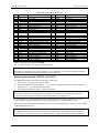
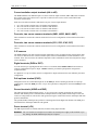
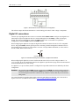
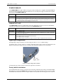
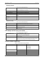
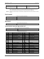
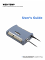
WEB-TEMP User's Guide Signal I/O Connections Current excitation output terminals (±IA to ±ID) The WEB-TEMP has four dedicated pairs of current excitation output terminals (±IA to ±ID). These terminals have a built-in precision current source to provide excitation for the resistive sensors used for RTD and thermistor measurements. Each current excitation terminal is dedicated to one pair of sensor input channels: IA+ is the current excitation source for channel 0 and channel 1 IB+ is the current excitation source for channel 2 and channel 3 IC+ is the current excitation source for channel 4 and channel 5 ID+ is the current excitation source for channel 6 and channel 7 Four-wire, two sensor common terminals (4W01, 4W23, 4W45, 4W67) These terminals are used as the common connection for four-wire configurations with two RTD or thermistor sensors. Four-wire, two sensor common terminals (IC01, IC23, IC45, IC67) These terminals are used as the common connection for four-wire configurations with two RTD or thermistor sensors. CJC sensors The WEB-TEMP has four built in high-resolution temperature sensors for thermocouple measurements. Each CJC sensor is dedicated to one of the four channel pairs, and is located behind the associated channel's screw terminal. These sensors measure the ambient temperature at the terminal block so that the cold junction voltage can be calculated. Digital terminals (DIO0 to DIO7) You can connect up to eight digital I/O lines to the screw terminals labeled DIO0 to DIO7. Each terminal is software configurable for input or output. A PU/D terminal is provided for pull-up/down configuration (explained below). If a digital bit is set up as an alarm, the bit is configured for output and assumes the state defined by the alarm configuration. Pull-up/down terminal (PU/D) All digital I/O lines are connected through 47k to the PU/D pin, which is floating by default. For a pull-up configuration, connect the PU/D pin to the +5V pin. For a pull-down configuration, connect the PU/D pin to the GND pin. Ground terminals (AGND and GND) The analog ground (AGND) terminals (pins 9, 19, 28, 38) provide a common ground for the sensor input channels. The AGND pins are isolated from the GND pin and from earth ground. Thermocouple sensors can connect to voltages that are referenced to earth ground, as long the isolation between the AGND pins and earth ground is maintained. The ground (GND) terminal (pin 48) provides a common ground for the digital I/O channels. The GND pin is isolated from the AGND pins and from earth ground. Power terminal (+5V) The +5V output terminal is isolated (500 VDC) from the analog input terminals. Caution! The +5V terminal is an output. Do not connect an external power supply to this terminal or you may damage the WEB-TEMP and possibly the computer. 21