1
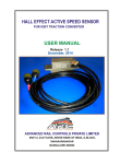
HALL EFFECT ACTIVE SPEED SENSOR
FOR 3 PHASE TRACTION MOTOR TYPES 6FRA6068 & 6FXA7059
FED FROM GTO CONVERTER
USER MANUAL
Release V.1.0
June 01, 2013
ADVANCED RAIL CONTROLS PRIVATE LIMITED
#59/1-2, 1 & 2 FLOOR (ABOVE BANK OF INDIA)
G-BLOCK, SAHAKARNAGAR
BANGALORE-560092
HALL EFFECT ACTIVE SPEED SENSOR USER MANUAL
INDEX
NO
CONTENTS
PAGE
1.0
INTRODUCTION
2
2.0
TECHNICAL DESCRIPTION
2
3.0
MECHANICAL CONSTRUCTION
4
4.0
TESTS
4
5.0
MOUNTING
4
6.0
PROCEDURE FOR CONNECTION OF
SENSOR AND CRO SETTINGS
8
7.0
CONNECTION DETAILS
10
8.0
TROUBLE SHOOTING
11
9.0
SCOPE OF SUPPLY
12
ADVANCED RAIL CONTROLS PVT. LTD.
1/13
HALL EFFECT ACTIVE SPEED SENSOR USER MANUAL
1. INTRODUCTION
The Rotational Speed Sensor working on Hall Effect principle as per CLW
specification is suitable for the traction motors used in WAG9, WAG9H, WAP7 &
WAP5 class of locomotives. TM type 6FRA6068 is used in WAG9, WAP7 &
WAG9H locomotives and TM type 6FXA7059 is used in WAP5. One set of Speed
Sensor consists of the sub-assemblies as mentioned in TABLE-2.
2. TECHNICAL DESCRIPTION
The working principle is illustrated in FIGURE-1. Two Hall Effect Sensors are
placed closely in the sensor housing (FIGURE-3) such that it is very close to the
toothed wheel. Associated with the Hall Sensors is a biasing magnet placed in
the very close proximity.
An iron-toothed wheel (FIGURE-4) having a uniform tooth pattern is mounted on
the motor shaft. The toothed wheel has 120 teeth. When the tooth wheel moves
under the Hall-Effect sensors, the magnetic field linking with the sensors vary
according to the tooth and trough of the wheel. The flux variation is measured by
the sensor and amplified. Two sensors are mounted with a phase shift of 90
electrical degrees. The outputs of these two sensors are used to resolve the
direction of the tooth wheel.
The final output coming out of the sensor is galvanically isolated and contains the
direction information. The output waveform is compatible to the Wiegand type
speed sensors used originally in the three phase locomotives. There are two
galvanically isolated output channels. In WAG9/WAG9H/WAP7 locomotives, only
one channel needs to be connected and the other channel is kept as spare. In
WAP5 locomotives, both the channels of the same sensor are to be connected to
the AS-Peri card.
ADVANCED RAIL CONTROLS PVT. LTD.
2/13
HALL EFFECT ACTIVE SPEED SENSOR USER MANUAL
For every revolution of the tooth wheel(ie. Motor shaft), 120 pulses are generated,
which is exactly same as the originally used Wiegand sensors. Due to this
compatibility, there is no need of any modifications in the electronics hardware and
software (ALG). The sensor will reliably reproduce the pulses from near zero
speed to above 3000 rpm, which has been tested and validated. The sensor has
been type tested and passed according to IEC-60571 & IEC-61373.
The data sheet of the speed sensor is given in FIGURE-2. The average pulse
height is close to 2V, which is compatible to the Wiegand Sensor. The pulse width is
also compatible to the Wiegand sensor.
Power supply to the sensor is provided from locomotive battery at 110V DC
(nominal). This is permitted to a variation of 77V to 137.5V according to IEC-60571.
The input is protected against any surges and transients to comply with IEC60571.
The output signals and power supply are taken using signal cables intended for
2
traction application. The cable used is of 2x1 mm EB irradiated cross linked type,
shielded with reinforcement for outdoor traction applications like that of speed
sensor. The length of the cable is approximately 270 cm each.
The signal outputs are terminated on 5-PIN circular connector (Female), bearing
ITT Cannon part number KPSE06E14-5SDZ. These connectors have a special
termination arrangement for providing a heat shrinkable boot shield termination,
which takes care of the stress relieving and ingress protection. These female
connectors can be direcery revolution of the tooth wheel (means motor shaft), 120
tly plugged into the 5-PIN male receptacles provided on the locomotive under
frame. The power supply cable is terminated in a 3-PIN circular connector of ITT
Cannon part number KPSE06E12-3SDZ. The corresponding panel mount male
receptacle bearing ITT Cannon part Number KPSE07F12-3P is supplied as loose
item along with the sensor. These connectors conform to MIL-C-26482 standard
ADVANCED RAIL CONTROLS PVT. LTD.
3/13
HALL EFFECT ACTIVE SPEED SENSOR USER MANUAL
In the present arrangement, there is no provision for providing the power supply
receptacle in the connector plate. Hence, a modified connector mounting plate is
also supplied as part of each sensor.
The sensor is totally sealed to comply with IP68 ingress protection class according
to IEC-60529.
3. MECHANICAL CONSTRUCTION
The Active Speed Sensor is mechanically 100% compatible to Wiegand type speed
sensor, needing no modifications in the mechanical housing. The toothed wheel also
has the same fixing dimensions and diameter. The sensor has three output cables,
two are for two sensor output channels and the third one is for the power supply (110
V DC from loco battery).
The drawings of the speed sensor and toothed wheel are given at FIGURE3&FIGURE-4).
4. TESTS
The sensor has been type tested and passed according to IEC-60571 & IEC-61373.
5. MOUNTING
Speed sensors have to be mounted on the housing which is part of the traction
motor.It is very important to notice that the speed sensors should not rub with the
wheel and the air gap should not be more than 1.6mm for satisfactory
performance.Ideal air gap is between 0,5mm and 1,5mm. If the air gap is more than
1.6mm there may be a chance of missing the pulses,so it is very important to take
care of the air gap while mounting.
After adjusting to suitable air gap mount the speed sensor with m8 screws provided.
If the air gap is too low, shims can be used to increase the gap to safe levels.
ADVANCED RAIL CONTROLS PVT. LTD.
4/13
HALL EFFECT ACTIVE SPEED SENSOR USER MANUAL
Biasing Magnet
Sensor Housing
Pulse
Amplification
Galvanic Isolation
Signal Output
Hall Effect Sensor
Signal Output
Tooth Wheel
110V DC
FIGURE -1
ADVANCED RAIL CONTROLS PVT. LTD.
5/13
HALL EFFECT ACTIVE SPEED SENSOR USER MANUAL
FIGURE -1
FIGURE-2
ADVANCED RAIL CONTROLS PVT. LTD.
6/13
HALL EFFECT ACTIVE SPEED SENSOR USER MANUAL
FIGURE-3
ADVANCED RAIL CONTROLS PVT. LTD.
7/13
HALL EFFECT ACTIVE SPEED SENSOR USER MANUAL
FIGURE-4
ADVANCED RAIL CONTROLS PVT. LTD.
8/13
HALL EFFECT ACTIVE SPEED SENSOR USER MANUAL
6. PROCEDURE FOR CONNECTION OF SPEED SENSOR
WITH CRO SETTINGS ON THE TEST BENCH.
Connect 3 pin female connector to dc power supply, pin A to be connected to positive of
the DC power supply and pin B to be connected to negative of the DC power
supply(FIGURE-7). Connect signal cable to CRO probes. In signal connector pin A to
be connected to positive probe of the CRO and Pin B to the ground probe.
CRO settings are given bellow.
Channel 1: set the voltage/div to 1volt.
Channel 2: set the voltage/div to 1volt.
Time/div: 25us.
If motor runs in anti-clockwise (looking from wheel end) direction of pulses should be in
positive direction as shown in theFIGURE-5.
FIGURE-5
ADVANCED RAIL CONTROLS PVT. LTD.
9/13
HALL EFFECT ACTIVE SPEED SENSOR USER MANUAL
If motor runs in clockwise direction (looking from wheel side) pulses should be in
negative direction as shown in the FIGURE-6.
FIGURE-6
When the traction motor runs in maximum speed (say 3000 RPM),the frequency
shown in CRO should be close to 6kHz.
Relation between frequency and RPM is mentioned in the below formula:
F=(RPM *120)/60 in Hz.
For eg: RPM =3000, then Frequency is,
F=(3000*120)/60
F=6000 Hz or 6KHz.
ADVANCED RAIL CONTROLS PVT. LTD.
10/13
HALL EFFECT ACTIVE SPEED SENSOR USER MANUAL
7 CONNECTION DETAILS
CRO
CH1
CH2
DC POWER SOURCE
110V
-
+
SIGNAL
SIGNAL
A
A+
A
B
B
B+
5 PIN CONNECTOR KPSE
(RED)KPSE 06E14-5SDZ
5 PIN CONNECTOR
(BLUE)KPSE06E14-5SDZ
3 PIN CONNECTOR
KPSE06E12-3SDZ
FIGURE-7
! PRECAUTIONS TO BE TAKEN WHILE MOUNTING.
5 pin connector carries signal and should not be connected to
High voltage.
3 pin connector is a power connector and is to be connected to 110 Volt. Pin A
to + (positive) and pin B to - (negative).
Check the gap before mounting using suitable test gauge.
Mounting surface to be clean and if the gap is too less use shims.
ADVANCED RAIL CONTROLS PVT. LTD.
11/13
HALL EFFECT ACTIVE SPEED SENSOR USER MANUAL
7. TROUBLE SHOOTING
Likely problems and solutions to the problems are listed in TABLE-1.
SL.
NO. LIKELY PROBLEMS
1
2
SOLUTIONS
Check the air gap and maintain
<1.6mm and if the gap is too less,
Error in tacho generator message then
use shims. Check the wheel
version and it must be W-3 version.
Check the air gap, mount the sensor
Speed not increasing more within the specified gap. If the air gap
is correct and problem is not solved
than 1 kmph
then Change the sub D connector
from respective sensor on SR rack.
Check the mounting of the sensor.
3
Speed exceed maximum Place the sensor with suitable
4
Check the mounting of the sensor.
Speed exceeds maximum Place the sensor with suitable
motor- damage possible. mounting specification
5
mounting specification
Check the sensor on test bench
Speed disturbance possible if no pulses are visible on CRO
then change the sensor with
new one.
TABLE-1
ADVANCED RAIL CONTROLS PVT. LTD.
12/13
MVB BASED GRAPHICAL DRIVER DISPLAY USER MANUAL
9. SCOPE OF SUPPLY
Sl.
No. Description of Sub-Assembly
1
2
3
Active Speed Sensor
Tooth Wheel
Cable Type H+S part number 12583003 :
RADOX TENUIS-TW/S EMC-SC,
600/1000V, 2x1 mm2 18AWG : (cable will
be connected with the sensor and crimped
with the specified female connector)
·
1) Signal Cable - 270 cm
Quantity (nos)/
Speed Sensor
1
1
2)Power Supply Cable - 270 cm
4
5
Fixing Bolt for Sensor & Tooth Wheel
1) Hex Hd Screw M8x25 Zn plated,
Grade 8.8 to IS:1364(Pt2)'92 (ISO-4017-88)
for fixing sensor
2) Hex socket Hd Cap screw M6x16-12.9 Zn plated
to IS:2269-95 and machined washer 6.4 to IS:2016 '67
&Steel to IS:2062 '99 Gr.A Type M6x16 Allen Screws
for fixing the Tooth Wheel.
1)ITT Cannon Connector KPSE07F12-3P
(Loose Supply) with fasteners
2)SS Plate to accommodate connector
receptacles
2
1
2
6
1
1
TABLE-2
Note: In one WAG-9/ WAG9H/ WAP7 locomotive, 06 such sensors are used.
In WAP5 locomotive, 04 such sensors are used.
ADVANCED RAIL CONTROLS PVT. LTD.
13/13
MVB BASED GRAPHICAL DRIVER DISPLAY USER MANUAL
CONTACT DETAILS
Mr. Krishnaraj
Sr. DGM Technical
ADVANCED RAIL CONTROLS PRIVATE LIMITED
#59/1-2, II FLOOR (ABOVE BANK OF INDIA)
G-BLOCK, SAHAKARANAGAR
BANGALORE-560 092
080-42401216
[email protected]
ADVANCED RAIL CONTROLS PVT. LTD.
13/13