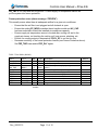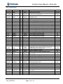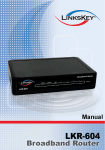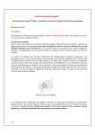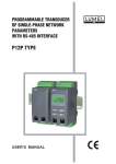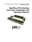
1
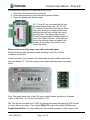
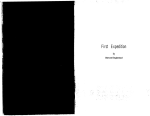
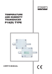
Controls User Manual Zone Comfort ™ hot water air handler and zoned distribution system with 4 zone iStat6 electronic controller Vortex Source Systems 45 Cowansview Rd. Cambridge, Ontario N1R 7L2 Phone: 888-781-8151 Fax: 888-670-2544 [email protected] www.vortexsource.com Controls User Manual – ZCxx-KI6 Table of Contents Controller Basics ..................................................................................................3 Controller Keypad.................................................................................................4 USER MODE .................................................................................................... 4 ADMIN MODE .................................................................................................. 4 Initial Controls Setup.............................................................................................5 Zone heating/cooling loads ............................................................................... 5 Cooling Control Mode ....................................................................................... 6 Two-Stage Air-Conditioning .............................................................................. 7 Cycle Timer (Pump Exerciser) .......................................................................... 7 Freeze Protection ............................................................................................. 7 Troubleshooting ................................................................................................ 8 Table 3 User Mode ..............................................................................................11 Table 4 Admin Mode ...........................................................................................12 Rev_20150715 Page 2 of 12 Controls User Manual – ZCxx-KI6 This document describes proper setup and use of the electronic controller for the Vortex Zone ComfortTM air handler with the iStat6 controller. Although the system will function when left at factory default settings, it is recommended that the installer read through this short manual in order to ensure the system has been setup to match the required heating and cooling loads and air-conditioning equipment installed, and to take advantage of the various features available. This control is capable of up to four zones though only two or three may be connected. Settings for unconnected zones can be ignored. Controller Basics The controller automatically adjusts blower motor speeds and engages relays for control of the system components. Through its LCD display and keypad, important system parameters may be configured and operating conditions may be monitored. When the controller keypad has not been pressed for a few minutes, the backlight will turn off and the display may go blank. Simply press any one of the buttons to wake up the controller. By default, the controller will display a short message describing the operating status of the system. Table 1 provides a list of the different possible status messages and their meaning. There are also a number of small icons that may appear around the edges of the display according to the current operating status. Table 2 gives an explanation of the different icons. Table 1 - status messages Message Meaning NO CALL HEATING COOLING FanOnly System is not currently receiving a call, all functions are off. There is currently a call for heating There is currently a call for cooling There is currently a call for continuous fan only and no heating or cooling Thermostat error (simultaneous heating & cooling calls from zone 1). Check wiring & ensure heat/cool thermostats are used Supply air is too cold, freeze protection has been activated. Compressor calls will be suspended until temperature rises and time delays are satisfied Pressing the button on the bottom of the control will operate the fan and pump for 20 seconds to verify operation. After 20 seconds, it returns to normal. TST ERR FROZEN TEST Table 2 - display icons Icon Flame Snowflake 4-blade fan 8-blade fan Rev_20150715 Meaning system is in heating mode system is in cooling mode blower is running below 50% blower is running above 50% Page 3 of 12 Controls User Manual – ZCxx-KI6 Controller Keypad By using the option and setting keys, different parameters and their current settings may be displayed and modified. Use the outer option keys to scroll through the available parameters, and use the inner setting keys to modify the parameter’s current setting (if available). By default, the control will remain in ‘user’ mode, in which a limited selection of parameters may be accessed. By entering ‘admin’ mode, additional parameters may be made available. Please exercise caution while in ‘admin’ mode, as these settings are meant to be accessed by the experienced user or installing contractor. A description of each of the modes is found below. USER MODE This is the basic display and operating mode, in which only a limited selection of parameters may be displayed. Refer to Table 3 for a description of each item displayed. ADMIN MODE This is the advanced display and configuration mode. It is intended only for the properly trained contractor. To enter ‘admin’ mode, press any button to illuminate the display backlight, then press and hold the two option (outer) buttons at the same time (‘user’ will be displayed at first, hold until ‘admin’ is displayed). You can now scroll through the display items by using the outer two option buttons, and adjust certain values using the inner two setting buttons. To return the control to ‘user’ mode simply wait a few minutes or press and hold both option buttons. Use Table 4 as a quick reference on the items available in this mode. Detailed descriptions on important parameters are found below. Rev_20150715 Page 4 of 12 Controls User Manual – ZCxx-KI6 Initial Controls Setup When first powering up the Zone Comfort air handler during commissioning, enter ‘admin’ mode on the controller and adjust the following settings to match the installed equipment. ZC_MODL – the model number of the Zone Comfort air handler. Options are ZC24, ZC30, ZC36, ZC42, ZC48, ZC60, and ZC100. This is used to set maximum airflow per zone based on damper size and total maximum airflow based on fan and motor capacity. This will be preset in the factory but should be verified by the installer. Refer to the table below. Model Max. Tonnage Damper Size Max. one zone airflow (cfm) Max. Airflow (cfm) ZC24, ZC30 2 1/2 8 in. 840 1200 ZC36 3 8 in. 840 1200 ZC42 3 1/2 10 in. 1440 1400 ZC48, ZC60, ZC100 5 10 in. 1440 1800 AC_CAP – the capacity (in tons) of the air-conditioning equipment. This setting impacts the amount of airflow when the system is in cooling mode. If a two-stage air-conditioner is installed, use the nominal (full capacity) tonnage. If air-conditioning is not installed, it is recommended to set this to match the maximum capacity of the Zone Comfort air handler (i.e. ZC24 = 2 tons, ZC48 = 4 tons). Refer to the table above. Caution!: An improper setting may result in coil freeze, excess noise or poor performance. GFAN_PC – the amount of airflow used for a continuous fan call, as a percentage of the maximum system airflow. The default setting is 50%. H_MIN – minimum heating airflow, as a percentage of the maximum system airflow. Default is 20%. H_MAX – maximum heating airflow, as a percentage of the maximum system airflow. Lower settings will mean longer heating cycles and improved air distribution throughout the home. Default setting is 100%. Zone heating/cooling loads With the Zone Comfort system, the amount of heating and cooling airflow supplied to each individual zone may be adjusted. This may be desired on systems which have a large difference in actual heating & cooling loads for each zone. Since many basements have a much lower cooling load, for example, it may make sense to Rev_20150715 Page 5 of 12 Controls User Manual – ZCxx-KI6 decrease the basement zone’s cooling airflow in order to increase cycle times and improve comfort. Modify the variables below to adjust these airflows. Ideally, zones should be of similar size or capacity. Z1_HL, Z2_HL, Z3_HL, Z4_HL – Heating loads for each zone, as a percentage of maximum heating airflow (H_MAX). Default for each is 50%. The total for all zones may exceed 100%. Note that a single zone calling will receive at least H_MIN. Multiple zones calling will not exceed H_MAX. Z1_CL, Z2_CL, Z3_CL, Z4_CL – Cooling loads for each zone, as a percentage of maximum cooling airflow (based on air-conditioner capacity AC_CAP). Default for each is 50%. The total for all zones may exceed 100%. Note that a single zone calling will receive at least the calculated minimum of MIN_TON (270 cfm default) x AC_CAP for single stage AC condensers and (MIN_TON-AC2_ADJ (270-90 cfm default)) x AC_CAP for 2-stage AC condensers. Multiple zones calling will not exceed MAX_TON (420 cfm default) x AC_CAP. D8_MAX, D10_MAX – Set the maximum airflow in cfm for 8 inch and 10 inch dampers respectively. D8_MAX is used by ZC24, ZC30 and ZC36. D10_MAX is used by the larger models. They should not be adjusted unless there are operational issues that cannot be fixed with the other settings. Consult the factory. Cooling Control Mode There are two modes of operation available for controlling cooling airflow: “fixed” and “auto”. Descriptions for each mode are found below. C_SPD – Cooling speed control mode, options are “fixed” and “auto”. Controls are in “fixed” mode by default. Note that in either mode, the cooling airflow will always be maintained between MIN_TON 270 (minimum default) and MAX_TON 420 cfm per ton (maximum default) of air-conditioner capacity (AC_CAP). In “fixed” mode, the cooling airflow will operate similar to that used in heating mode, adjusting based on the zones currently calling for cooling and the corresponding settings for zone cooling loads (Z1_CL, Z2_CL, Z3_CL and Z4_CL). In “auto” mode, the airflow will adjust to maintain the supply air temperature at the chosen cooling setpoint (COOL_SP). This mode can provide better control of indoor comfort, helping to ensure adequate dehumidification is taking place. Caution: for proper operation, the supply air temperature sensor must be installed downstream of the cooling coil and measuring well-mixed cold air. COOL_SP – The cooling setpoint temperature for auto cooling mode. Default setting is 11oC (52oF). Lower setpoint temperatures will lead to lower airflow, increased dehumidification and comfort, but may decrease overall cooling capacity and efficiency. PID_PROP, PID_INT, PID_DB, PID_RAMP – These settings affect the proportional, Rev_20150715 Page 6 of 12 Controls User Manual – ZCxx-KI6 integral, deadband, and ramp rate used for the P.I.D. cooling speed control when in auto mode. It is recommended that these settings only be changed by someone who has a firm understanding of P.I.D. control schemes and only if the response rate of the fan is unsatisfactory. Contact Vortex if you believe there’s an issue with these settings. MIN_TON, MAX_TON – These settings affect the minimum and maximum airflow respectively. They should not be adjusted unless there are operational issues in cooling mode. Consult the factory. Two-Stage Air-Conditioning An output is available on the low-voltage terminal strip for the control of a two-stage air-conditioner. When a cooling call is present, second stage will be activated in fixed mode if the cooling demand exceeds AC2_MIN, determined based on the current zone calls and their respective cooling loads Z1_CL, Z2_CL, Z3_CL and Z4_CL. If in auto mode, second stage will be activated if the number of current cooling calls (dampers open) equals or exceeds AC2_DMP. AC2_ADJ – Adjusts the air flow down when the first stage of a two-stage AC system is active. The default is 90 cfm/ton which is approx. a 1/3 reduction in airflow (most 2-stage condensers reduce capacity by 1/3 during first stage). This should not be adjusted unless there are operational issues in cooling mode. Consult the factory. AC2_MIN – In fixed mode, the cooling airflow at which 2nd stage is activated, set by default to 80%. Decreasing this value will cause 2nd stage to be activated sooner, leading to full capacity and colder supply air temperatures. AC2_DMP – In auto mode, the minimum number of dampers open at which 2nd stage is activated, set by default set to 2 dampers open (any 2 zones calling). Decreasing this value will cause 2nd stage to be activated sooner, leading to full cooling capacity and higher airflow. Note that higher values increases run time in first stage which will improve efficiency and may reduce airflow noise. Cycle Timer (Pump Exerciser) The Zone Comfort includes an optional cycle timer or pump exerciser feature which may need to be enabled depending on the hot water source and local regulations. When enabled, the cycle timer will run the heating circulating pump for 30 seconds every 24 hours. CT_MODE – Cycle timer mode. Set to 1 to enable, 0 to disable. Cycle timer is disabled by default. Freeze Protection In order to prevent the heat exchanger coils from freezing during cooling, the Zone Rev_20150715 Page 7 of 12 Controls User Manual – ZCxx-KI6 Comfort includes a freeze protection feature. If the measured supply air temperature drops below the freeze protection temperature FRZ_TMP, the signal to the airconditioner contactor is interrupted. In order to prevent short-cycling of the compressor, this feature includes two settable delay intervals: FRZ_DLY sets the amount of time the supply air temperature has to remain below FRZ_TMP before the alarm is triggered; and FRZ_DLY2 sets the amount of time until the compressor is allowed to come back on, once the supply air temperature has returned to above FRZ_TMP. Note: This feature will only turn off the AC compressor signal. It will not protect the home or air handler from freezing house temperatures or improper fresh air connections such as from a heat recovery ventilator. FRZ_TMP – The freeze protection setpoint temperature. Default value is 3 °C. Lowering this value will decrease sensitivity of the freeze protection feature. FRZ_DLY – Amount of time (in minutes) to wait before acknowledging a freeze protection condition. Default setting is 3 minutes. Increasing this value will decrease sensitivity of the freeze protection feature. FRZ_DLY2 – Amount of time in minutes to wait before bringing the A/C compressor back on, once the measured supply air temperature has returned to a safe value. Default setting is 2 minutes. Troubleshooting Warning: The homeowner can diagnose many issues from the main controller on the front of the air handler but any diagnostics or servicing inside the air handler (blower compartment) should only be performed by a qualified service person. High voltages are present. No Display – If pushing one of the four front buttons does not refresh the display, there may be no power to the air handler, or the transformer has failed or the controller has failed. No Heating – Note the controller display icons: flame = heating mode. If the flame icon is not displayed, heating calls on zones 2,3 and 4 are ignored. A brief heating call from zone 1 is required to switch the controller to heating mode. If in doubt, turn the heat on all zones. Test Mode – pushing the button on the bottom (underneath) of the control will run the pump and fan for 20 seconds. Damper position will not change. No Cooling - Note the controller display icons: snowflake = cooling mode. If the snowflake is not displayed, cooling calls on zones 2, 3 and 4 are ignored. A brief cooling call from zone 1 is required to switch the controller to cooling mode. If in doubt, turn the cooling on all zones. Thermostat calls – The status screen (default) will show any calls detected from any thermostat including continuous fan ON (Table 1). Using the outer keys, the user can scroll through the screens to see individual thermostat calls and fan speed (Table 3). Rev_20150715 Page 8 of 12 Controls User Manual – ZCxx-KI6 If a thermostat is calling but not detected by the control: 1. Check the thermostat and its connections 2. Check thermostat wiring at the thermostat and air handler. 3. Check the 8gang relay indicator lights. W1, Y1 and G1 are connected directly from the thermostat terminal strip. W2, Y2, W3, Y3, W4 and Y4 are filtered through the 24vac relay (left) allowing only heating calls during heating mode and only cooling calls during cooling mode. The 8gang relay converts 24vac thermostat signals to digital signals for input to the iStat6 controller. If the lights are on but the controller does not respond, the problem is the wiring to the control or the control has failed. Blower motor never fully stops, even with no demand signal Ensure the thermostats have been wired according to the Zone Comfort Installation Instructions. Ensure the blower motor speed control board has a jumper installed across the terminals labeled “P”. The motor speed control board and the jumpers are shown below. Note: The green signal light of the EVO motor control flashes according to its speed output to the motor. Ex. 5 long 3 short blinks = 53% Tip: The fan can be tested from 0-100% by placing the primary thermostat in FAN ON with no other calls on any zone. Then, adjust GFAN_PC up and down within ADMIN mode. Pump Does Not Run – For any heating call, the controller provides a 12vdc output to the Rev_20150715 Page 9 of 12 Controls User Manual – ZCxx-KI6 pump relay. The relay runs the pump (120vac) and provides a 24vac signal to the 8gang relay board. If the light is on at the 8 gang relay, the wiring to the pump or the pump itself is the problem. Air Conditioning Does Not Run – For any cooling call, the controller provides a 24vac signal directly to the Y1out connection to the A/C condenser and also to the 8gang relay indicator light. If the light is on, the problem is not in the air handler. If the light is off, the problem would be wiring or controller. Second Stage Air Conditioning Does Not Run – Check settings in Table 4. For second stage, the controller provides a 12vdc output to the 2nd stage relay. The relay provides 24vac to the terminal strip Y2out. Dampers get stuck when changing position When a zone damper tries to change position under high airflow or static pressure, it may become stuck in a half-open position. The controller provides a delay on damper closing in order to prevent this from occurring. If this is an issue, increase the delay setting (DMP_DLY) in ‘admin’ mode (default delay is 20 seconds). Also, check that the following values are correct in the program: ZC_MODL, AC_CAP, H_MIN, MIN_TON, D8_MAX, D10_MAX and all zone settings Z1_HL, Z1_CL etc. Too much airflow to a single zone, causing noise This can occur due to undersized ductwork or improper setup of the air handler zone heating/cooling loads. The problem may be fixed by reducing the amount of airflow designated to the problem zone. See above section on zone heating/ cooling loads to adjust the airflow used for each zone. Note that H_MIN, MIN_TON and AC_CAP will override zone settings. Installing a 2-stage air conditioner will reduce the minimum cooling airflow for single zones. Alarm message “TST ERR” There is a simultaneous call for heating and cooling on zone one, indicating an error with thermostat wiring or setup. Ensure that all the zone thermostats are wired as per the Zone Comfort Installation Instructions, and are configured for 1 heat / 1 cool systems. Note that when zone one has set the system in heating mode, cooling calls on all other zones are ignored. Likewise, when zone one has set the system in cooling mode, heating calls on all other zones are ignored. Not enough humidity removal in cooling mode The Zone Comfort air handler controls humidity during cooling through use of the “auto” cooling speed mode (set C_SPD to “auto”). See the Cooling Control Mode section above. Supply or return air temperature (SA_TMP or RA_TMP) reads -50 °C This indicates the supply air temperature sensor is not properly connected to the controller. Ensure that the sensor is connected as per the wiring diagram found in the Zone Comfort Installation Instructions and that no wires have become loose. Rev_20150715 Page 10 of 12 Controls User Manual – ZCxx-KI6 RA_TMP is not used and can be ignored. A failed supply air temperature sensor will put the system into freeze protection. Freeze protection errors (alarm message “FROZEN”) This usually occurs when there is inadequate airflow for a given air-conditioner. Ensure that the air filter is not plugged and all ductwork is open Ensure the setting ZC_MODL matches the air handler model and AC_CAP has been selected to match the installed air-conditioner capacity Ensure supply air temperature sensor is located after cooling coil and in the supply air stream, not touching the cooling coil, heat source, plumbing, etc. Ensure the cooling setpoint temperature COOL_SP is not set too low Decrease sensitivity of the freeze protection feature (see Freeze Protection above). Set FRZ_TMP lower and/or FRZ_DLY higher. Table 3 User Mode (default) Line 1 ZoneComf SA_TMP Line 2 #### ###.# C RA_TMP FAN_PC Z1_H Z1_C Z2_CALL Z3_CALL Z4_CALL ZC4 ###.# C #### % (0)Off/(1)On (0)Off/(1)On (0)Off/(1)On (0)Off/(1)On (0)Off/(1)On ##.## REV Rev_20150715 Set. D D Type Display Input Description Display status of system Supply air temperature Return air temperature (display only, not used in D Input calcs.) D calc Convert FAN_CFM into percentage 0-100 D Input Zone 1 thermostat heating input D Input Zone 1 thermostat cooling input D Input Zone 2 valid thermostat call D Input Zone 3 valid thermostat call D Input Zone 4 valid thermostat call D Display Program name and revision number * note: "D" in set. indicates variable is for display only and is not settable Page 11 of 12 Default NO CALL 3.00 Controls User Manual – ZCxx-KI6 Table 4 Admin Mode Line 1 ZoneComf Line 2 #### ZC_MODL #### AC_CAP SA_TMP RA_TMP FAN_PC GFAN_PC H_MIN H_MAX Z1_HL Z1_CL Z2_HL Z2_CL Z3_HL Z3_CL Z4_HL Z4_CL Z1_H Z1_C Z2_CALL Z3_CALL Z4_CALL #### ###.# C ###.# C #### % #### % #### % #### % #### % #### % #### % #### % #### % #### % #### % #### % (0)Off/(1)On (0)Off/(1)On (0)Off/(1)On (0)Off/(1)On (0)Off/(1)On C_SPD AC_STG2 AC2_MIN #### (0)Off/(1)On #### % AC2_DMP COOL_SP DMP_DLY CT_MODE PID_PROP PID_INT PID_DB PID_RAMP FRZ_TMP FRZ_DLY #### #### C #### sec (0)Off/(1)On ###.# %/C ##.## %/sec/C ###.# C ###.# %/sec #### C #### min FRZ_DLY2 ZC4 Modbus #### min ##.## REV #### Rev_20150715 Set. D D D D D D D D D Type Display Text Setting Text Setting Input Input calc Setting Setting Setting Setting Setting Setting Setting Setting Setting Setting Setting Input Input Input Input Input Text Setting Setting Setting Text Setting Setting Setting Setting Setting Description Display status of system Set the Zone Comfort Model Capacity of air-conditioner in tons, select from available choices. Supply air temperature Return air temp. (display only, not used in calcs.) Convert FAN_CFM into percentage 0-100 Continuous Fan airflow as a percent of maximum. Setpoint of minimum heating airflow as a percentage Setpoint of maximum heating airflow as a percentage Zone 1 heating speed percentage Zone 1 cooling speed percentage Zone 2 heating speed percentage Zone 2 cooling speed percentage Zone 3 heating speed percentage Zone 3 cooling speed percentage Zone 4 heating speed percentage Zone 4 cooling speed percentage Zone 1 thermostat heating input Zone 1 thermostat cooling input Zone 2 valid thermostat call Zone 3 valid thermostat call Zone 4 valid thermostat call Cooling airflow control mode (FIXED = based on demand from zones, AUTO = controlled based on measured supply air temperature) Is the air conditioner 2-stage? Minimum airflow to activate 2nd stage cooling. How many dampers must be open to activate 2nd stage cooling? Cooling setpoint of supply air temperature Damper Delay to close damper in seconds Cycle Timer On or Off (Once per day pump exerciser) Cooling PID Proportional value Setting Setting Setting Setting Setting Cooling PID Integral value Cooling PID Deadband value Cooling PID Ramp Rate value Freeze alarm setpoint Freeze Delay 1 - wait time to activate freeze alarm Freeze Delay 2 - wait time to restore operation after a Setting freeze alarm D Display Program name and revision number Setting Modbus address * note: "D" in set. indicates variable is for display only and is not settable Page 12 of 12 Default NO CALL ZC24 1 50 25 100 50 50 50 50 50 50 50 50 FIXED OFF 80 2 Dampr 11 20 OFF 3 0.2 0.5 5 2 3 2 3.00 136