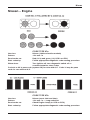
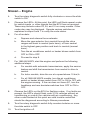
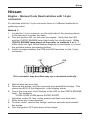
1
SEE APPLICABLE COVERAGE SHEETS FOR VEHICLE APPLICATIONS Mitsubishi, Nissan, Mazda and Eunos Vehicle Communication Manual July 2010 Use in conjunction with the applicable Scanner User’s Reference Manual and Diagnostic Safety Manual. Before operating this unit, please read this manual and any applicable Scanner User’s Manual. Safety Notices..................................... Refer Diagnostic Safety Manual Quick Reference Contents Listing .... page 5 Using the Scanner Module ................ Refer to relevant User's Manual for more information Vehicle Identification Mitsubishi, Nissan, Mazda and Eunos Vehicle Communication Manual July 2010 BEFORE OPERATING THIS UNIT, PLEASE READ THIS MANUAL CAREFULLY, ALSO PAY PARTICULAR ATTENTION TO THE SAFETY PRECAUTIONS IN THIS MANUAL AND THE DIAGNOSTIC SAFETY MANUAL. Vehicle Identification The information, specifications, and illustrations in this manual are based on the latest information available at the time of publication. The SCANNER manufacturer and the vehicle manufacturers reserve the right to make equipment changes at any time without notice. Copyright © 2010 Snap-on Technologies Inc. Vehicle Identification Quick Reference Contents Detailed Contents are at the beginning of each part Part 1 — Vehicle Identification..............................................................6 Gives you general information on vehicle identification. Information on SCANNER startup troubleshooting also is included. Part 2 — Vehicle Connection and Diagnostics...................................10 Mazda and Eunos........................................................................................ 12 Mitsubishi..................................................................................................... 30 Nissan........................................................................................................... 46 Appendix B – Vehicle Does Not Communicate With Scanner............76 General Note For All Vehicles All SCANNER and Reference Manual directions are as if the operator is standing at the back of the vehicle facing forward. Vehicle Identification Part 1 - Vehicle Identification Contents Vehicle Identification..............................................................................6 Entering the Vehicle Identification........................................................7 System Selection....................................................................................8 SCANNER Connection Message.............................................................8 Vehicle Identification After you select the desired manufacturer software the SCANNER then requires you to enter the vehicle’s ID. This is done by selecting the manufacturer, the year of the vehicle, model and engine displacement. Pressing N at any point in the first few steps lets you back up to the previous step to correct a choice. Pressing N at the final step will return to the start of the identification process. ‘AUSTRALIA’ is for vehicles that are manufactured for the Australian market and ‘USED IMPORTS’ refers to vehicles that were originally sold new in Japan and have since been exported to other countries, including Australia and New Zealand. The SCANNER does not list every model that is available but does cover the more popular vehicles that are available. CAUTION: Although every effort has been made to provide accurate information, due to the many models available and the lack of information available for these vehicles the information that is contained in the SCANNER for these Used Import vehicles may not always be accurate for the particular model being tested. Vehicle Identification Entering The Vehicle Identification After you select the vehicle manufacturer, the screen displays the following message (example): SELECT MODEL YEAR MODEL: MODEL YEAR: 1983 ENGINE: Press the thumbpad or scroll the thumbwheel up or down to display the correct year for the vehicle you are testing. Then press Y to enter the model year. The display now shows the model year that you selected in the previous step and asks you to select the model name: SELECT MODEL TYPE MODEL: MAGNA MODEL YEAR: 1995 ENGINE: Press the thumbpad or scroll the thumbwheel up or down and press Y to select the model name. The display now shows the model name that you selected in the previous step and asks you to select the engine displacement by pressing the thumbpad or scrolling up or down to the correct engine, some vehicles may only have one choice: SELECT ENGINE TYPE MODEL: MAGNA MODEL YEAR: 1995 ENGINE: SCROLL TO SELECT ENGINE Press the thumbpad or scroll the thumbwheel up or down and press Y to select the engine displacement. The display now shows the engine that you selected in the previous step. Transmission and Air Conditioning Information At the end of vehicle identification, the screen may display the complete model and engine identification, similar to this: SELECT VEHICLE OPTIONS: > A/T WITH A/C A/T WITHOUT A/C M/T WITH A/C M/T WITHOUT A/C Vehicle Identification Scroll arrow to select correct option of vehicle being tested and press Y. NOTE: A/T = Automatic Transmission M/T = Manual Transmission A/C = Air Conditioning If the identification is correct, press Y to store the identification in memory. If the identification is not completely correct, press N to return to the start of the identification steps. System Selection For some vehicles, the SCANNER provides engine and transmission test capabilities. After you press Y to store the identification for these vehicles, the screen will display this message: SELECT SYSTEM ENGINE AUTO TRANS ANTI-LOCK BRAKES AIRBAG (SRS) Using the thumbpad or thumbwheel, move the cursor to the desired system and press Y. The above display does not appear for vehicles without transmission tests. SCANNER Connection Message After you press Y to store the vehicle identification or after you select the engine or transmission system for testing, the screen display tells you how to connect the SCANNER to the vehicle. For example: CONNECT DL-16 ADAPTER WITH S-15 KEY TO 16-PIN CONNECTOR UNDER RH DASH. PRESS Y TO CONTINUE. Connect the SCANNER to the vehicle as per on screen instructions. After the SCANNER is connected to the vehicle, press Y to proceed to the MAIN MENU. Vehicle Identification PAGE INTENTIONALLY LEFT BLANK Part 2 — Vehicle Connection and Diagnostics Contents Connecting the SCANNER to the vehicle ........................................ 11 Special Notes on Graph Mode ......................................................... 11 Note on Functional Tests .................................................................. 11 Mazda and Eunos – ........................................................................... 12 Special Notes . .................................................................................. 13 Connector Types . ............................................................................. 14 Engine ............................................................................................... 17 Automatic Transmission ................................................................... 23 ABS ................................................................................................... 25 SRS – Airbag . ................................................................................... 26 Body Systems . ................................................................................. 29 Mitsubishi – ....................................................................................... 30 Special Notes . .................................................................................. 31 Connector Types................................................................................ 33 Engine................................................................................................ 36 Automatic Transmission.................................................................... 38 ABS ................................................................................................... 41 SRS ................................................................................................... 45 Nissan – ............................................................................................. 46 Special Notes . .................................................................................. 47 Connector Types................................................................................ 49 Engine................................................................................................ 51 Automatic Transmission.................................................................... 70 ABS.................................................................................................... 73 SRS – Airbag . ................................................................................... 74 10 Vehicle Connection & Diagnostics Connecting the SCANNER to the Vehicle This section of the manual gives you drawings of the vehicle diagnostic connectors and tells you which SCANNER adapter to use. The carmakers are listed alphabetically for quick-reference. After you have identified the vehicle, the SCANNER display then tells you where to find the diagnostic connector and which vehicle adapter to use. Note on Functional Tests Functional tests are not applicable to Ethos software. Special Notes on Graph Mode Note that not all vehicle systems will be able to be displayed in the Graph Mode due to the communication type. It may also take several attempts to establish communication in Graph Mode. This is not a fault of the scan tool or the vehicle. 11 Mazda and Eunos Mazda and Eunos CAUTION FOR ABS AND SRS SYSTEMS Before attempting any repairs on vehicles fitted with ABS or SRS Airbag, systems observe all precautions the manufacturer specifies for these systems. Mazda and Eunos Australia Vehicles Mazda Australia vehicles are vehicles that are produced to be sold as new on the Australian market. They may or may not be manufactured in Australia but comply with Australian design laws. When selecting a vehicle ID on the SCANNER ensure the correct initial selection is made: MAZDA - AUSTRALIA. EUNOS – AUSTRALIA. Mazda and Eunos Used Import Vehicles Used Import vehicles are vehicles that were sold new in Japan and have since been exported to other countries including Australia and New Zealand. The SCANNER does not list every model that is available but does cover the more popular vehicles that are available. When selecting a vehicle ID on the SCANNER ensure the correct initial selection is made: MAZDA – USED IMPORTS. EUNOS – USED IMPORTS. Caution - Important note for Used Imports Although every effort has been made to ensure the correct information has been supplied for each vehicle there may be differences between what appear to be the same models. Entering initial vehicle ID When entering the initial vehicle identification ensure you have first selected the correct data base for the vehicle being tested, that is whether it is a Mazda Australia vehicle or a Mazda Used Import vehicle. If you are unsure about a vehicle’s origin check the compliance plates on the vehicle. 12 Mazda and Eunos Special notes Attention!! Important: Reading Codes Mazda Auto Code Read systems do not transmit a “pass code” when there are no faults detected by the ECU. If you are unsure whether the system is functioning correctly induce a known code and retest the vehicle. When reading codes on the SCANNER – whether it is Live Data, Auto Code Read or Manual Code Read – and you are unsure about the code, try pulling a known sensor then running the code check again. Then see if the code has registered with the vehicle and been transmitted to the SCANNER module correctly. Remember to clear any false codes you may induced in the system. MIL STATUS parameter on data lists The MIL STATUS parameter that appears on live data lists displays the PCM (Powertrain Control Module) command to the Malfunction Indicator Light or MIL. Most Mazda live data vehicles do not have a MIL on the dash to indicate that a problem may be present. If the MIL STATUS is ON then it is most likely that there is a hard fault present and there is a fault code present. If the MIL STATUS is OFF and there are fault codes present then the codes are not current, eg they were set previously. Slow to communicate When the SCANNER is initiating communication with some vehicles it may take up to 10 seconds before codes or data is displayed on the screen. This is dependant on the communication type of the vehicle being tested and is not controlled by the SCANNER module. Functional Tests When performing Functional Tests make sure all of the on-screen instructions are followed precisely so that the test is performed correctly. Not following the procedures may produce faulty test results. Entering initial vehicle ID When entering the initial vehicle identification ensure you have first selected the correct data base for the vehicle being tested, that is whether it is a Mazda Australia vehicle or a Mazda Used Import vehicle. If you are unsure about a vehicle’s origin check the compliance plates on the vehicle. General note on clearing codes from any system If the code clearing method described on the SCANNER is not effective for that vehicle, then remove a battery terminal for at least one minute and then recheck the system. 13 Mazda and Eunos Special notes cont. CAN-1A or CAN-1B adapter (for VCI or Legacy software use only) When testing certain Mazda vehicles the CAN-1A or CAN-1B adapter will need to be used. When the CAN adapter is used the Scanner will need to “download” an operating program to it to enable it to communicate with the vehicle being tested. This may take up to 30 seconds during which time the Scanner may appear to be inactive. This is normal operation with the CAN adapter. This “download” only happens once each time the CAN adapter is used. If more than 1 minute has passed and the Scanner is still displaying “IN PROGRESS” remove the adapter from the vehicle for 10 seconds, reinstall the adapter, re-ID the vehicle and re-attempt communication. NOTE: This software will not function with the CAN-1 adapter. It must have the newer CAN-1A or CAN-1B adapter. What is CAN? Controller Area Network, or CAN for short, is a system employed when multiple electronic controllers are used and they need to share information. It is used in many different areas apart from automotive applications. It is however becoming popular among the automotive manufacturers and is appearing on more vehicles. In order for a scan tool to communicate with the CAN system it must become part of the CAN system, so a special adapter is used as an “interface” between the vehicle and the scan tool. CAN Adapter and Vehicle Low Battery Voltage If the Scanner and CAN adapter are being used on a vehicle where the vehicle battery may not be at full charge and the vehicle is started the vehicle system voltage may drop low and cause the CAN adapter to reset and lose the download program. It may cause the Scanner to appear “frozen” or not updating data information. To recommence communication exit to the MAIN MENU for the vehicle being tested and reselect TEST MENU and then CODES or DATA. This will reprogram the CAN adapter and recommence communication. 14 Mazda and Eunos SCANNER Communication Types The SCANNER module will present the relevant communication type for the vehicle system being tested, whether it is Codes & Data, Auto Code Read or Manual Code Read. Mazda vehicles covered by the SCANNER from 1984 are Auto Code Read for engine, automatic transmission and ABS (on later models, where fitted). SRS Airbag is only Manual Code Read where fitted. Mazda started introducing live data on Australian vehicle engines and automatic transmissions in late 1995, starting with 4 cylinder 323/Astina models. Since then it has been introduced into different models across the Mazda range. The SCANNER supports live Codes and Data for engine and automatic transmission for these vehicles. Note: Some automatic transmissions may support live data codes only and not data. Connector Types Mazda vehicles use two types of diagnostic connectors as detailed in the following diagrams. Connect to Ground VEHICLE CONNECTOR 6-pin or 6+1-pin connector can be located under bonnet or under dash. Single pin connector not used on early models **SEE FOLLOWING INFORMATION ABOUT IDENTIFYING THE STI CONNECTOR Figure 3:1 Use Multi-2-B & E for both connectors. Ensure Multi-2 black 1-pin ground lead is attached to a known good vehicle ground. 15 Mazda and Eunos **IMPORTANT INFORMATION** Identifying the STI Connector – MECS Most Mazda engine controllers with the 6-pin self-test connector have two similar single-wire connectors in the engine compartment. One is the self-test input connector (STI); the other is a TACH connector. You have to connect the Multi-2 E connector to the vehicle STI lead to trigger the self-tests. CAUTION: Do not connect the SCANNER to the TACH connector. Doing so can severely damage the diagnostic test equipment. Identifying the STI connector can be difficult. Connector color, wire colors, and connector location varies, depending on model, year, and engine. You MUST identify the STI connector before connecting the SCANNER. The SCANNER will give you on-screen instructions to help you locate the proper connector. To confirm STI connector identification, connect one lead of a 12-volt test lamp to the connector terminal and the other lead to ground; then crank the engine. If the test light flashes, you are connected to the TACH connector. If the test light doesn’t flash while cranking the engine, you’re probably connected to the STI connector. This is where you connect the SCANNER. GROUND MAZDA SHORT TO GROUND THIS PIN ONLY FOR MANUAL CODES E B MAZDA MULTI-2 ADAPTER CONNECT MULTI-2-E TO: GREEN CONNECTOR 1-PIN (STI) CONNECT MULTI-2-B TO: GREEN CONNECTOR 6-PIN PLUS CONNECT GROUND EXTENSION TO CHASSIS WHITE TACH CONNECTOR – DO NOT CONNECT TO THIS LEFT SIDE REAR OF ENGINE COMPARTMENT Figure 3:2 CAUTION: Make sure this is the STI connector and not TACHO connector. Read “Identifying the STI Connector” for more details. 16 Mazda and Eunos Connectors continued 17-pin connector located under bonnet on left hand side near strut tower or fire wall, with a cap that is labelled “DIAGNOSTIC” on it. Can be grey or black. Figure 3:3 Toyota-2 adaptor. Other adapters used may include the OBDII and DL-16 that use specific keys. Always read and follow on-screen instructions regarding adapters and keys required when connecting to vehicles. 17 Mazda and Eunos Mazda – Engine The SCANNER supports Auto Code Read and Codes & Data for Mazda engines. Codes and Data For live Codes & Data vehicles there is one SCANNER Engine test menu available, this TEST MENU has a few different options when selected. The screen will automatically display the correct one for the vehicle being tested. An example of each follows: MAIN MENU—ENGINE >TEST MENU CUSTOM SETUP OTHER SYSTEMS When TEST MENU is selected, the screen will then display one of three menus with options as below. 1) TEST MENU >CODES ONLY 2) TEST MENU >CODES ONLY DATA INPUTS *DATA MISC. DATA (NO CODES) DATA (NO CODES) DATA FUEL/AIR *Vehicles in 1995 & 1996 do not have DATA MISC. 3) TEST MENU >CODES ONLY O2 MONITORS PENDING CODES CODES ONLY DATA (NO CODES) FREEZE FRAME (on option 1,2,3) This selection will display any codes transmitted by the vehicle. All codes are displayed with the codes number and description. NOTE: When a code is transmitted by the vehicle to the SCANNER the code will indicate there may be a problem either in the WIRING between the ECU and the indicated sensor/actuator or in the indicated sensor/actuator. DATA (NO CODES) (on option 1,2,3) This selection displays engine data that is transmitted to the SCANNER by the vehicle. For descriptions and explanations of the various parameters see the Australian Data Parameter Manual. Note: This selection does not display every parameter available. 18 Mazda and Eunos Mazda – Engine DATA INPUTS (on option 2) This data selection displays engine data related to sensor inputs to the PCM, for example:- RPM readings, coolant readings, intake air temperature. Various vehicles will display different parameters and not necessarily the examples mentioned. For descriptions and explanations of the various parameters see the Australian Data Parameter manual. DATA FUEL/AIR (on option 2) This data selection displays parameters related to fuel and air readings, for example:- airflow, air temperature, oxygen sensor. Various vehicles will display different parameters and not necessarily the examples mentioned. For descriptions and explanations of the various parameters see the Australian Data Parameter manual. DATA MISC. (on option 2) This data selection displays various parameters that do not fit the other data categories, for example:- air-conditioner switch, power steering pressure switch. Various vehicles will display different parameters and not necessarily the examples mentioned. For descriptions and explanations of the various parameters see the Australian Data Parameter manual. 02 MONITORS (on option 3) This option allows access to 9 different tests that look at various ways the Oxygen Sensor is working. Not every vehicle supports all of the tests. Refer to the Global OBD-II/EOBD Reference Manual for specific information on these tests. FREEZE FRAME (on option 3) When the first DTC or Diagnostic Trouble Code is set the PCM will log various data parameters from the engine data list. These parameters can assist in determining what may have set the DTC. If there are no DTC’s set then there is no Freeze Frame data recorded by the PCM. PENDING CODES (on option 3) This selection will display any pending codes transmitted by the vehicle. Pending codes are set by operating conditions are not within normal range and that have not met all the criteria for setting a code. For example some sensor readings not within normal range may require a specific number of drive cycles , engine running time or engine operating before they set a code. NOTE: When a code is transmitted by the vehicle to the SCANNER the code will indicate there may be a problem either in the WIRING between the ECU and the indicated sensor/actuator or in the indicated sensor/actuator. 19 Mazda and Eunos Auto Code Read – Engine IMPORTANT NOTE for Auto Code Read vehicles: These systems have no output from the vehicle unless a code has been set in the PCM/ECM. This mean that the vehicle may appear to not respond to the SCANNER, if you are unsure try setting a code manually and then reading the code on the screen. See Scanner User’s Manual for further Auto Code Read information. The SCANNER will read and display any fault present codes on the screen. Auto Code Read Functional Tests The FUNCTIONAL TESTS selection is available for some Mazdas. If this option is available for the Mazda you are testing, FUNCTIONAL TESTS will be displayed on the MAIN MENU. When you select FUNCTIONAL tests from the main menu, the screen displays: FUNCTIONAL TEST MENU: >EXHAUST MONITOR SWITCH TEST Some early-model Mazdas have only the EXHAUST MONITOR functional test available. Oxygen Sensor Test When you select OXYGEN SENSOR TEST from the Mazda FUNCTIONAL TESTS menu, the screen displays: 20 MAKE SURE ENGINE IS RUNNING AND WARM (IN CLOSED LOOP) BEFORE MONITORING THE EXHAUST OXYGEN CONTENT. PRESS Y TO CONTINUE Mazda and Eunos Mazda – Engine This function lets you monitor the feedback signal from the exhaust gas oxygen sensor. After you start the engine and warm it to normal operating temperature, press Y. The screen displays: HOLD ENGINE AT 2000 RPM TO MONITOR EXHAUST OXYGEN SENSOR. ............................... EXHAUST___________LEAN As instructed, accelerate the engine to 2000 rpm and hold it there. LEAN is displayed on the screen when the exhaust is lean, and RICH is displayed when the exhaust is rich. LED 3 on the screen will flash to indicate that the SCANNER is receiving a signal from the exhaust gas oxygen sensor. Press N to return to the FUNCTIONAL TESTS menu. Switch Test Select this function and the screen displays: WITH KEY ON AND ENGINE OFF, TEST EACH SWITCH. AS ANY SWITCH STATE CHANGES, DISPLAY ALTERNATIVES HIGH/LOW & LED 3 GOES OFF/ON. PRESS Y TO CONTINUE, N TO EXIT. This function lets you check certain on-off switch circuits. Press N to return to the FUNCTIONAL TEST MENU. Press Y and the screen displays: TEST ANY SW: NEUTRAL/CLUTCH, INHIBITOR, IDLE, HEADLAMP, BRAKE LAMP, BLOWER, A/C, REAR DEFROSTER, WATER THERMO. SWITCH STATE_____HIGH Not all switches displayed apply to every vehicle. Refer to Mazda service procedures and specifications for availability of specific vehicle switch tests. As you test each switch, the SWITCH STATE parameter should alternatively display HIGH or LOW each time a switch status changes. Also, screen LED 4 turns on when this parameter displays LOW, and off when HIGH. See the table on the next page for individual switch test instructions. Press N to return to the FUNCTIONAL TESTS MENU. 21 Mazda and Eunos Mazda – Engine SWITCH TEST INSTRUCTIONS Neutral/Clutch Make sure the engine is off. With the transmission in gear, the SWITCH STATE parameter will alternate HIGH/ LOW as the clutch is engaged and disengaged. Return the transmission to neutral after the test. Inhibitor (A/T only) Make sure the engine is off. The SWITCH STATE parameter will alternate HIGH/LOW as the transmission is placed in gear and returned to neutral. Idle The SWITCH STATE parameter will alternate HIGH/LOW as the gas pedal is pressed and released. Headlamp The parameter will alternate HIGH/LOW as the headlamps are turned on and off. Turn off the headlamps after the test. Brake Lamp The SWITCH STATE parameter will alternate HIGH/LOW as the brake pedal is pressed and released. Blower Turn the blower switch to the high position. The SWITCH STATE parameter will alternate HIGH/LOW as the blower switch position changes. Turn the blower off after the test. A/C With the blower set to low, the SWITCH STATE parameter will alternate HIGH/LOW as the air conditioner is turned on and off. Turn off the blower and air conditioner after the test Rear Defroster The SWITCH STATE parameter will alternate HIGH/LOW as the rear defroster is turned on and off. Turn off the rear defroster after the test. Water Thermo The SWITCH STATE parameter will alternate HIGH/LOW as the water thermo switch is disconnected. Reconnect the switch after the test. Base Timing Check In this mode, the SCANNER grounds the vehicle check connector. This causes the ECU to place the engine in the base timing mode so that you can check or adjust ignition timing. When you select BASE TIMING CHECK from the Mazda FUNCTIONAL TESTS menu, the screen displays: 22 THE VEHICLE CHECK CONNECTOR HAS BEEN GROUNDED BY THE SCANNER. BASE IGNITION TIMING CAN NOW BE CHECKED. PRESS N WHEN DONE. Mazda and Eunos Mazda – Engine Clear Codes for all types Clear codes from the SCANNER is available only for live data Mazda engines, it is accessed from the CODES ONLY exit menu. For Auto Code Read vehicles clear code instructions are detailed in the CODE FUNCTIONS menu. 23 Mazda and Eunos Mazda – Automatic Transmission Mazda Automatic Transmissions that are electronically controlled can be either Auto Code Read or Codes & Data. Codes & Data Test Menu MAIN MENU—TRANS >TEST MENU CUSTOM SETUP OTHER SYSTEMS When TEST MENU is selected, the screen will then display either of two menu options. 1) or TEST MENU >CODES ONLY 2) TEST MENU >CODES ONLY DATA INPUTS CODES ONLY DATA (NO CODES) (on option 1,2) This selection will display any codes transmitted by the vehicle, all codes are displayed with descriptions. NOTE: When a code is transmitted by the vehicle to the SCANNER the code will indicate there may be a problem either in the WIRING between the ECU and the indicated sensor/actuator or in the indicated sensor/actuator. DATA (NO CODES) (on option 2) This menu selection displays transmission data parameters that are transmitted from the vehicle to the SCANNER. For descriptions and explanations of the various parameters see the Australian Data Parameter Manual. Note: This selection does not display every parameter available. DATA INPUTS (on option 2) This data selection displays data related to sensor inputs to the PCM, for example:- gear lever positions and engine RPM. Various vehicles will display different parameters and not necessarily the examples mentioned. For descriptions and explanations of the various parameters see the Australian Data Parameter Manual. 24 Mazda and Eunos Auto Code Read – Automatic Transmission IMPORTANT NOTE for Auto Code Read vehicles: These systems have no output from the vehicle unless a code has been set in the PCM/ECM. This mean that the vehicle may appear to not respond to the SCANNER, if you are unsure try setting a code manually and then reading the code on the screen. Clear Codes Clear codes is only available for Mazda automatic transmissions with Live Data, it is accessed from the CODES ONLY exit menu. For Auto Code Read refer to clear codes in the CODE FUNCTION menu for clear codes procedures. Mazda ABS CAUTION: Before attempting any repairs on vehicles fitted with ABS systems observe all precautions the manufacturer specifies for these systems. The SCANNER supports Auto Code Read and Codes and Data for Mazda ABS systems. Please refer to Scanner VCS Coverage Application Sheets for vehicles and systems covered in each software section. Auto Code Read IMPORTANT NOTE for Auto Code Read vehicles: These systems have no output from the vehicle unless a code has been set in the ABS control unit. This means that the vehicle may appear to not respond to the SCANNER, if you are unsure try setting a code manually and then reading the code on the screen. 25 Mazda and Eunos Mazda SRS Airbag CAUTION: Before attempting any repairs on vehicles fitted with SRS Airbag systems observe all precautions the manufacturer specifies for these systems. The SCANNER supports Manual Code Read and Codes and Data for Mazda SRS Airbag systems. Please refer to Scanner VCS Coverage Application Sheets for vehicles and systems covered in each software section. Manual Code Read For Manual Code Read vehicles follow on-screen instructions, the codes must be read on the dash mounted “SRS” lamp. During Manual Code Read the SCANNER is not connected to the vehicle but may display on-screen instructions. The SCANNER provides a list of the code numbers and their descriptions on screen, located also under the CODE FUNCTIONS selection. NOTE: When a code is transmitted by the vehicle to the SCANNER the code will indicate there may be a problem either in the WIRING between the ECU and the indicated sensor/actuator or in the indicated sensor/actuator. 26 Mazda and Eunos Retrieving Past Codes – SRS Some SRS Airbag systems can store Past Codes (also know as History or Memory codes).These are codes that may be intermittent or set previously and not cleared. s To retrieve Past Codes for the SRS Airbag system follow the procedure listed below. SCN terminal 1) Locate the SCN terminal in the diagnostic connector which is located under the bonnet on the left side of the engine bay. 2) Turn the ignition on and wait for the 6 second SRS lamp prove out. The SRS lamp will illuminate for 6 seconds while it tests the SRS system. If the lamp goes out and does not flash again there are no current codes in the system. If there are current codes present repair these first. 3) Using a jumper wire ground the SCN terminal. 4) If any Past codes are present they will be displayed on the SRS lamp. 27 Mazda and Eunos Clear Codes – SRS Codes are cleared when the fault is rectified and the ignition is cycled off for at least 10 seconds and on again. On systems that have Past or History codes these need to be cleared using the following procedure. Clearing Past Codes After rectifying all current codes use this procedure to clear past codes. 1) Turn the ignition to on and wait for 6 seconds until the SRS lamp has gone out. 2) Ground the SCN terminal in the 17-pin diagnostic connector as detailed below : 3 times for 1 – 1.5 seconds. 1 – 1.5 secs s OFF s s GROUND 3) 28 1 2 3 When the SRS lamp stops flashing the codes are erased. Turn the ignition off and then on again and check the SRS lamp does not flash to ensure no more codes are present. Mazda and Eunos Airbag Code Type CODE NO. 01 Mazda Body Systems Several different systems can be located in the Body Systems section depending on the model of the vehicle. These systems can include: • Body Control Module (BCM) • Electronic Automatic Temperature Control (EATC) • Electronic Power Sterring (EPS) • Generic Electronic Module (GEM) • Instrument Cluster Module (ICM) • Passenger Junction Box (PJB) The Codes and Data sections of these systems operate similarly to other type systems like engine and transmissions etc. Note: Not all vehicle may support all parameters shown in these lists. 29 Mitsubishi Mitsubishi CAUTION FOR ABS AND SRS SYSTEMS Before attempting any repairs on vehicles fitted with ABS or SRS Airbag, systems observe all precautions the manufacturer specifies for these systems. Mitsubishi Australia Vehicles Mitsubishi Australia vehicles are vehicles that are produced to be sold as new on the Australian market. They may or may not be manufactured in Australia but comply with Australian design laws. When selecting a vehicle ID on the SCANNER ensure the correct initial selection is made: MITSUBISHI – AUSTRALIA. Mitsubishi Used Import Vehicles Used Import vehicles are vehicles that were sold new in Japan and have since been exported to other countries including Australia and New Zealand. The SCANNER does not list every model that is available but does cover the more popular vehicles that are available. When selecting a vehicle ID on the SCANNER ensure the correct initial selection is made: MITSUBISHI – USED IMPORTS. Caution - Important note for Used Imports Although every effort has been made to ensure the correct information has been supplied for each vehicle, there may be differences between what appear to be the same models. Entering initial vehicle ID When entering the initial vehicle identification ensure you have first selected the correct data base for the vehicle being tested, that is whether it is a Mitsubishi Australia vehicle or a Mitsubishi Used Import vehicle. If you are unsure about a vehicle’s origin, check the compliance plates on the vehicle. Note that not all Mitsubishi Australia vehicles are manufactured in Australia but were sold as new vehicles in Australia and comply with Australian vehicle design rules. 30 Mitsubishi Mitsubishi Used Import GDI Important Information Please read the following information regarding Mitsubishi Used Import GDI vehicles before diagnosing with Scanner. Important Information 1) GDI vehicles use 2 types of Throttle Bodies: a) Cable Controlled Throttle Bodies b) Electronic Controlled Throttle Bodies (no cable), Mitsubishi call these ETV (Electronic Throttle Valve). 2) When testing a GDI vehicle and an ETV Code or any Throttle Body Code is present DO NOT replace the Throttle Body without testing it first. (Some Cable controlled Throttle Body systems may give false codes that cannot be cleared, see below for a manual code retrieval procedure to verify codes.) 3) Refer to Mitsubishi procedures for testing Throttle Bodies. This usually involves checking the resistance of the Throttle Sensor and ETV motor. 4) If you are unsure seek further advice before replacing the Throttle Body. Mitsubishi Manual Code Retrieval Procedure How to Get Codes Ground pin 1 in 16 pin diagnostic connector. The Engine Check Light flashes codes. Long & short flashes are used, long flash = 10’s, short flash = 1’s. How to Clear Codes Disconnect battery terminal for one minute. 31 Mitsubishi Code List for GDI Manual Codes 11 12 13 14 15 16 17 18 21 22 23 24 25 26 27 28 29 31 32 34 35 36 37 38 39 41 42 43 44 45 47 49 52 32 Oxygen (O2) sensor Air Flow sensor Intake temperature sensors Throttle Position Sensor TPS (SUB) Idle speed control motor position sensor Power supply voltage Closed Loop Temperature Not Reached Cranking signal (Ignition Switch – ST) Engine Coolant Temperature Sensor Crankshaft Position Sensor Camshaft Position Sensor Vehicle Speed Sensor Barometric Pressure Sensor Closed Throttle Position Switch Power Steering Pressure Switch or Injector Control Circuit A/C Switch Park/Neutral Position Switch Knock Sensor or EVAP System MAP Sensor or EGR fault Volume Air Flow sensor reset signal Radiator Fan Control Relay Circuit Ignition Timing Adjustment signal Volumetric Efficiency or P/N switch Crankshaft Position Sensor fault Left bank Heated Oxygen Sensor (Front) Injectors failure Fuel Pump fault EGR-System fault Ignition coil, Ign Power Transistor Unit failure Idle Air Control Position Injectors A/C compressor clutch relay Ignition Coil #2  53 54 55 56 58 59 61 62 64 65 66 69 71 72 73 77 78 79 81 82 83 84 87 88 89 91 92 94 95 99 Ignition coil #3 & #6 Immobiliser Communications IAC Valve Position sensor Fuel Pressure Fail High Intake Air Heated Oxygen (O2) sensor (rear) Transaxle Torque Reduction Signal Induction Control Valve Position Sensor Alt FR Signal Power Steering Pressure Switch Failure Brake Vacuum Switch Oxygen (O2)sensor Vacuum Control Solenoid Valve (TRC) Ventilation Control Solenoid Valve (TRC) Fuel Tank Pressure Differential Sensors Sub Accelerator Position Sensor (APS SUB) Main Accelerator Position Sensor (APS MAIN) Main Throttle Position Sensor TPS (MAIN) Long-term fuel compensation Short-term fuel compensation Long-term fuel compensation Short-term fuel compensation Calculation Load Fuel Control Condition Fuel System fault ETV Control ETV Motor feedback ETV Communication ETV Motor (1) ETV Motor (2) Mitsubishi Special notes Slow to communicate When the SCANNER module is initiating communication with some vehicles it may take up to 10 seconds before the CODES & DATA selection is displayed on the screen. During this time the YES and NO buttons may not respond if pressed, wait until the CODES & DATA selection is displayed to continue with the SCANNER. Functional tests When performing Functional Tests make sure all of the SCANNER onscreen instructions are followed precisely so that the test is performed correctly. Not following the procedures may produce faulty test results. Entering initial vehicle ID When entering the initial vehicle identification ensure you have first selected the correct data base for the vehicle being tested, that is whether it is a Mitsubishi Australia vehicle or a Mitsubishi Used Import vehicle. If you are unsure about a vehicle’s origin, check the compliance plates on the vehicle. Note that not all Mitsubishi Australia vehicles are manufactured in Australia but were sold as new vehicles in Australia and comply with Australian vehicle design rules. Testing GDI Vehicles Note: If you are diagnosing a Mitsubishi Used Import GDI vehicle, please refer to the beginning of the Mitsubishi section for Important Information regarding these systems. Reading Codes When reading codes on the SCANNER – whether it is Live Data or Auto Code Read – and you are unsure about the code, try pulling a known sensor then running the code check again. Then see if the code has registered with the vehicle and been transmitted to the SCANNER correctly. General note on clearing codes from any system If the code clearing method described on the SCANNER is not be effective for the vehicle, then remove a battery terminal for at least one minute and recheck the system. ABS Communication When starting communication with the ABS system, 1) ensure the vehicle ignition is OFF, 2) press Y for CODES & DATA and then switch the ignition ON. 33 Mitsubishi SCANNER Communication Types The SCANNER will present the relevant communication type for the vehicle system being tested, whether it is Codes & Data or Auto Code Read. The SCANNER supports live Codes and Data for Engine and Automatic Transmission, some ABS and some SRS Airbag on vehicles that use the 12-pin and 16-pin diagnostic connector. Vehicles that do not use the 12-pin or 16-pin connectors are Auto Code Read for engine and automatic transmission. Refer to the applicable coverage sheets for specific Mitsubishi vehicle coverage. 34 Mitsubishi Connector Types Mitsubishi vehicles use five types of diagnostic connectors as detailed below. 3-pin connector SIDE POWER MAY BE REQUIRED 4-pin connector 3-pin or 4-pin connector is located underbonnet. Figure 3:6 Use Hyundai-2 with Mitsu-1AU for both connectors. SIDE POWER MAY BE REQUIRED 9-pin connector located in glove box. Figure 3:7 Use Hyundai-2 with Mitsu-1AU. 35 Mitsubishi Connector Types continued SIDE POWER MAY BE REQUIRED 12-pin connector Figure 3:8 Use Hyundai-2 with battery power. SRS Airbag only SIDE POWER MAY BE REQUIRED Mithy-1 or Mitsu-3AU 12-pin connector Figure 3:9 3AU. 36 When testing SRS Airbag systems use Hyundai-2 with Mithy-1 or Mitsu- Mitsubishi Connector Types continued 16-pin connector Figure 3:10 DL-16 (Use with specified personality key) Use DL-16 with specified key. To Scanner Data Cable Used key indicated on Scanner screen Some vehicles use the 12-pin & 16-pin connector together. Figure 3:11 connectors. Use Mitsu-1 with DL-16 with specified key and connect to both 37 Mitsubishi Mitsubishi - Engine The SCANNER supports Live Codes & Data and Auto Code Read for Mitsubishi engines. Note: If you are diagnosing a Mitsubishi Used Import GDI vehicle, please refer to the beginning of the Mitsubishi section for Important Information regarding these systems. Codes and Data **ATTENTION: IMPORTANT INFORMATION** When proceeding from the SCANNER connector screen message the SCANNER will “pause” while it initiates communication with the vehicle. It is important that the vehicle ignition is in the ON position at this time. Once the below screen is displayed you must press Y for CODES & DATA within 4 seconds to maintain communication with the vehicle. If communication is lost with the vehicle the screen will display a “NO COMMUNICATION” message on the screen, press N and re-enter the vehicle identification. MAIN MENU—ENGINE >CODES & DATA CUSTOM SETUP FUNCTIONAL TESTS The SCANNER will display engine data together with any engine codes transmitted by the vehicle on the screen. Any codes that are present are displayed, along with its description, at the top of the on-screen data list. If there are no codes present the SCANNER will display (NO CODES PRESENT). For descriptions and explanations of the various parameters see the Australian Data Parameter Manual. NOTE: When a code is transmitted by the vehicle to the SCANNER the code will indicate there may be a problem either in the indicated sensor/actuator or in the WIRING for that sensor/actuator. A sample of a screen display with no codes present. RPM____825 O2 (mV)___898 TPS(V)_____1.12 ** CODES & DATA. OK TO DRIVE. ** (NO CODES PRESENT) LOAD(%)____ 27 COOLANT(º)________56 Sample of a screen display with codes present. 38 RPM____825 O2 (mV)___898 INTEGRATR__102 ** CODES & DATA. OK TO DRIVE. ** 13 AIR TEMP SENSOR 14 THROTTLE POSITION SENSOR LOAD(%)_______ 27 COOLANT(º)________56 Mitsubishi Actuator Tests – Engine The SCANNER supports actuator tests for some live data vehicles; there are various tests available under this menu option. The tests available for each vehicle is dependent on what tests that vehicle supports, not every vehicle supports every Functional Test The SCANNER provides on screen instructions on how to perform the tests. Some tests are performed with the ignition on and some with the engine running, follow the on screen prompts to perform the tests available for the vehicle being tested. During testing you must monitor the selected actuator with a meter or by listening for actuator activation. The engine controller does not monitor the selected actuator. A completed test does not mean the actuator was activated. The SCANNER can only monitor the engine controller ON/ OFF commands to the actuator. Codes & Data for Used Import Vehicles When using Codes & Data on used import vehicles there may be some parameters displayed on the screen that may not be applicable to the vehicle being tested. For example, “AIRFLOW” and “BOOST (MAP) (KPA)” may be both displayed but the vehicle may only have a MAP sensor fitted. The readings from the AIRFLOW meter can be ignored as the vehicle does not use this reading. Similarly the vehicle may display codes for both sensors but again ignore the code referencing the component that is not fitted. Auto Code Read See Scanner Plug-in User’s Manual for further Auto Code Read information. The SCANNER will read and display any fault present codes on the screen. Mitsubishi vehicles transmit a constant flash as a pass code. Clear Codes Clear codes is available only for Live Data Mitsubishi engines, it is accessed from the CODES & DATA exit menu. Some early model live data vehicles do not support clear codes. For Auto Code Read vehicles clear code instructions are detailed in the CODE FUNCTIONS menu. 39 Mitsubishi Mitsubishi – Automatic Transmission Mitsubishi Automatic Transmissions that are electronically controlled can be either Auto Code Read or Live Data. Codes and Data MAIN MENU—TRANS >CODES & DATA CUSTOM SETUP FUNCTIONAL TESTS Note:- Not all vehicles will have Functional Tests. The SCANNER will display automatic transmission data together with any automatic transmission codes transmitted by the vehicle on the screen. Any codes that are present are displayed, along with its description, at the top of the on-screen data list. If there are no codes present the screen will display (NO CODES PRESENT). For descriptions and explanations of the various parameters see the Australian Data Parameter Manual. NOTE: When a code is transmitted by the vehicle to the SCANNER the code will indicate there may be a problem either in the indicated sensor/actuator or in the WIRING for that sensor/actuator. A sample of a screen display with no codes present. RPM_________825 TPS(V)____________1.12 ** CODES & DATA. OK TO DRIVE. ** (NO CODES PRESENT) PULSE GEN A__820 PULSE GEN B_____0 Sample of a screen display with codes present. 40 RPM_________825 TPS(V)____________1.12 ** CODES & DATA. OK TO DRIVE. ** 31 PULSE GEN A OPEN 41 SHIFT SOL A OPEN PULSE GEN A__820 PULSE GEN B_____0 Mitsubishi Functional Tests – Automatic Transmission The SCANNER supports functional tests for some live data vehicles, there are various tests available under this menu option, some vehicles will only have one test. The tests available for each vehicle is dependent on what tests that vehicle supports, not every vehicle supports every Functional Test The SCANNER provides on screen instructions on how to perform the tests. Some tests are performed with the ignition on and some with the engine running, follow the on screen prompts to perform the tests available for the vehicle being tested. During testing you must monitor the selected actuator/solenoid with a meter or by listening for actuator/solenoid activation. The engine controller does not monitor the selected actuator/solenoid. A completed test does not mean the actuator/solenoid was activated. The SCANNER can only monitor the engine controller ON/OFF commands to the actuator/solenoid. Early Automatic Transmission Early model electronically controlled transmission (with 9-pin connector) ie Magna TM and TN are Auto Code Read only. Vehicle connector is located at top of open glove box. Connect to vehicle by using Hyundai-2 and Mitsu-1AU. Testing Procedure 1. Connect to vehicle. 2. Key on engine off will display code 10 (no ignition signal) and this is correct as crank is not rotating. 3. Start vehicle and code 10 should no longer be outputted. 4. With engine running (road test if necessary) any fault codes will be displayed on the screen. 5. Caution: No not turn off vehicle ignition before viewing fault codes as this will clear/eliminate any logged fault codes. 6. No fault codes detected is a system pass. 41 Mitsubishi Clear Codes – Automatic Transmission Clear codes is available on Mitsubishi automatic transmissions with Live Data, it is accessed from the CODES & DATA exit menu. Some early model live data vehicles do not support clear codes. For Auto Code Read vehicles refer to clear codes in the CODE FUNCTION menu for clear codes procedures. 42 Mitsubishi Mitsubishi ABS CAUTION: Before attempting any repairs on vehicles fitted with ABS systems observe all precautions the manufacturer specifies for these systems. The SCANNER supports Live Codes & Data, Auto Code Read and Manual Code Read for some Mitsubishi ABS equipped vehicles. Codes and Data MAIN MENU—ABS >CODES & DATA CUSTOM SETUP The SCANNER will display ABS data together with any ABS codes transmitted by the vehicle on the screen. Any codes that are present are displayed, along with its description, at the top of the on-screen data list. If there are no codes present the screen will display (NO CODES PRESENT). For descriptions and explanations of the various parameters see the Australian Data Parameter Manual. IMPORTANT NOTE: When starting communication with the ABS system, 1) ensure the vehicle ignition is OFF, 2) press Y for CODES & DATA and then switch the ignition ON. NOTE: When a code is transmitted by the vehicle to the SCANNER the code will indicate there may be a problem either in the indicated sensor/actuator or in the WIRING for that sensor/actuator. A sample of a screen display with no codes present. BATTERY (V)___12.2 ** CODES & DATA. (NO CODES PRESENT) LF WHEEL(KPH)__ 20 BRAKE SW___OFF OK TO DRIVE. ** RH WHEEL(KPH)__20 Sample of a screen display with codes present. BATTERY (V)___12.2 BRAKE SW___OFF ** CODES & DATA. OK TO DRIVE. ** 13 RH REAR SENSOR OPEN 41 RHF SOL INLET VALVE LF WHEEL(KPH)__ 20 RH WHEEL(KPH)__20 43 Mitsubishi Auto Code Read – ABS See Scanner Plug-in User’s Manual for further Auto Code Read information. The SCANNER will read and display any fault present codes on the screen. Mitsubishi vehicles transmit a constant flash as a pass code. NOTE: When a code is transmitted by the vehicle to the SCANNER the code will indicate there may be a problem either in the indicated sensor/actuator or in the WIRING for that sensor/actuator. See Clear Codes for clear codes procedure. Manual Code Read – ABS The procedures for accessing the ABS codes are contained in the SCANNER under the Code Functions menu. During Manual Code Read the SCANNER is not connected to the vehicle but may display on-screen instructions. 44 Mitsubishi Manual Code Read – ABS 16-pin connector Ground pin 1 of the 16-pin diagnostic connector, then turn the ignition on. Figure 3:13 ABS manual code gathering. The SCANNER provides a list of the code numbers and their descriptions on screen, located also under the CODE FUNCTIONS selection. NOTE: The code displayed by the vehicle will indicate there may be a problem either in the WIRING between the ECU and the indicated sensor/actuator or in the indicated sensor/actuator. 45 Mitsubishi Clear Codes – ABS Live Data Vehicles Clear codes is available on Mitsubishi ABS, it is accessed from the CODES & DATA exit menu. Magna TR/TS, Verada KR/KS Locate the 2-pin erasure connector at the ABS ECU. ABS ECU for Sedans is in left side of boot behind side trim:- ABS ECU for Wagons in left side of cargo area behind side trim. 1. Bridge the 2 pins of the erasure connector. 2. Turn the ignition ON for at least one second and then OFF again. 3. Disconnect the 2 pins of the erasure connector and turn the ignition back ON. 4. This will erase one ABS code. Repeat steps 1 to 3 to erase any further codes. Magna TE/TF/TH, Verada KE/KF/KH manual clear code procedure 1. With the ignition off depress the brake pedal. 2. Switch the ignition on and wait for the ABS lamp to go out. 3. Release the brake pedal and then press and release the brake pedal 9 times within 20 seconds. 4. The ABS lamp will illuminate for 1 second to confirm the code erasure. 46 Mitsubishi Mitsubishi SRS Airbag CAUTION: Before attempting any repairs on vehicles fitted with SRS Airbag systems observe all precautions the manufacturer specifies for these systems. The SCANNER supports Live Codes & Data for some Mitsubishi SRS Airbag systems. Codes and Data MAIN MENU—SRS >CODES & DATA CUSTOM SETUP The SCANNER will display SRS data together with any SRS codes transmitted by the vehicle on the screen. Any codes that are present are displayed, along with its description, at the top of the on-screen data list. If there are no codes present, the screen will display (NO CODES PRESENT). For descriptions and explanations of the various parameters see the Australian Data Parameter Manual. NOTE: When a code is transmitted by the vehicle to the SCANNER the code will indicate there may be a problem either in the indicated sensor/actuator or in the WIRING for that sensor/actuator. A sample of a screen display with no codes present. FAULT #1(MIN)___1FAULT #2(MIN)___1 ** CODES & DATA. OK TO DRIVE. (NO CODES PRESENT) ERASE CYCLES___0 ** Sample of a screen display with codes present. FAULT #1(MIN)___1FAULT #2(MIN)___1 ** CODES & DATA. OK TO DRIVE. 22 DRIVERS AIRBAG SQUIB(OPEN) 43 SRS WARNING LIGHT CIRCUIT OPEN ERASE CYCLES___0 ** NOTE: - there is only 2 or 3 parameters that are displayed for SRS Airbag. Clear Codes – SRS Clear codes is available on Mitsubishi SRS Airbag, it is accessed from the CODES & DATA exit menu. 47 Nissan Nissan CAUTION FOR SRS SYSTEMS Before attempting any repairs on vehicles fitted with SRS Airbag, systems observe all precautions the manufacturer specifies for these systems. Nissan Australia Vehicles Nissan Australia vehicles are vehicles that are produced to be sold as new on the Australian market. They may or may not be manufactured in Australia but comply with Australian design laws. When selecting a vehicle ID on the SCANNER ensure the correct initial selection is made: NISSAN – AUSTRALIA. Nissan Used Import Vehicles Used Import vehicles are vehicles that were sold new in Japan and have since been exported to other countries including Australia and New Zealand. The SCANNER does not list every model that is available but does cover the more popular vehicles that are available. When selecting a vehicle ID on the SCANNER ensure the correct initial selection is made: NISSAN – USED IMPORTS. Caution - Important note for Used Imports Although every effort has been made to ensure the correct information has been supplied for each vehicle, there may be differences between what appear to be the same models. Entering initial vehicle ID When entering the initial vehicle identification ensure you have first selected the correct data base for the vehicle being tested, that is whether it is a Nissan Australia vehicle or a Nissan Used Import vehicle. If you are unsure about a vehicle’s origin, check the compliance plates on the vehicle. Note that not all Nissan Australia vehicles are manufactured in Australia but were sold as new vehicles in Australia and comply with Australian vehicle design rules. 48 Nissan Special notes Slow to communicate When the SCANNER is initiating communication with a 14-pin connector type vehicle it may take up to 10 seconds before codes or data is displayed on the screen. Functional tests When performing Functional tests on vehicles with the 14-pin connector make sure the on-screen instructions are followed precisely so that the test is performed correctly. Locating diagnostic connectors The 12-pin and 14-pin diagnostic connectors may be located in various positions. Sometimes the connector is fixed and sometimes it is left loose on the end of a wiring loom. When it is loose on the end of a wiring loom it may be necessary to “hunt” for it. For example if it is behind the centre console it may be tucked under the carpet or if it is in a kickpanel only the loom may be visible. It may be necessary to pull the loom free to locate the connector on the end of the loom. Entering initial vehicle ID When entering the initial vehicle identification ensure you have first selected the correct data base for the vehicle being tested, that is whether it is a Nissan Australia vehicle or a Used Import vehicle. If you are unsure about a vehicle’s origin, check the compliance plates on the vehicle. Note that not all Nissan Australia vehicles were manufactured in Australia but were sold as new vehicles in Australia and comply with Australian vehicle design rules. 49 Nissan SCANNER Communication Types The SCANNER supports live Codes and Data for Engine and Automatic Transmission on vehicles that use the grey Nissan 14-pin diagnostic connector and vehicles with the 16-pin diagnostic connector. Vehicles that use the Nissan 12-pin diagnostic connector are Auto Code Read for Engine and Manual Code Read for Automatic Transmission. Vehicles that have no diagnostic connector are Manual Code Read. SRS Airbag systems that are supported by the SCANNER are Manual Code Read. There are two exceptions to this: 1) The 1995 to 1997 Micra Constant Velocity Transmission (CVT) is Manual Code Read; it uses the Grey 14-pin diagnostic connector. 2) The 1987 to 1991 Pulsar N13 1.6L & 1.8L engines use a GMH type 12-pin diagnostic connector and are live Codes and Data. Refer to the applicable coverage sheets for specific Nissan vehicle coverage. 50 Nissan Connector Types Nissan vehicles use four types of diagnostic connectors, two 12-pin types, a 14 pin and a 16 pin. 12-pin connector Figure 3:14 Use Nissan-1. GMH type 12-pin, Pulsar N13 only Figure 3:15 Use GM-1. For Australian Pulsar N13 only. 51 Nissan Connector Types Grey 14-pin connector* Figure 3:16 Use Nissan-2. *See Special Notes at the beginning of this Nissan section. 16-pin connector Figure 3:17 Use DL-16 with specified key. Always read and follow on-screen instructions regarding adapters and keys required when connecting to vehicles. 52 Nissan Nissan – Engine Codes & Data The SCANNER allows for Codes & Data on all Nissan vehicles with the 14-pin connector and Pulsar N13 with the GMH type 12-pin connector. The SCANNER will display engine data and any engine codes, with descriptions, transmitted by the vehicle to the SCANNER. Live Codes and Data For live Codes & Data vehicles there is two different Engine test menus’ available. The SCANNER will automatically display the correct one for the vehicle being tested. An example of each follows: Type 1: (Australian Pulsar N13 only) MAIN MENU—ENGINE >CODES & DATA CUSTOM SETUP Type 2: (all other live data) MAIN MENU—ENGINE >TEST MENU CUSTOM SETUP FUNCTIONAL TESTS OTHER SYSTEMS 53 Nissan Nissan – Engine Type 1: Codes & Data (Australian Pulsar N13 only) The SCANNER will display engine data together with any engine codes transmitted by the vehicle on the screen. Any codes that are present are displayed, along with its description, at the top of the on-screen data list, if there are no codes present the SCANNER will display (NO CODES PRESENT). NOTE: When a code is transmitted by the vehicle to the SCANNER the code will indicate there may be a problem either in the indicated sensor/actuator or in the WIRING for that sensor/actuator. A sample of a screen display with no codes present. RPM____825 O2 (mV)___898 INTEGRATR__102 ** CODES & DATA. OK TO DRIVE. ** (NO CODES PRESENT) OPEN/CLSD LOOP__CLSD O2 STATUS__RICH Sample of a screen display with codes present. 54 RPM____825 O2 (mV)___898 INTEGRATR__102 ** CODES & DATA. OK TO DRIVE. ** 22 THROTTLE POSITION (TP) SENSOR 33 MAP SENSOR HIGH OPEN/CLSD LOOP__CLSD O2 STATUS__RICH Nissan Nissan – Engine Type 2: Codes and Data Test Menu Vehicles that support this type of Codes & Data use the grey 14-pin diagnostic connector. This type was first used in 1990 and was then introduced over the model range in the following years. MAIN MENU—ENGINE >TEST MENU CUSTOM SETUP FUNCTIONAL TESTS OTHER SYSTEMS When type 2 TEST MENU is selected, the screen will then display another menu with six options. TEST MENU >CODES ONLY IGN & IDLE CONTROL INPUTS/OUTPUTS FUEL/AIR METERING AUX EMMISIONS FUEL TRIM OR TEST MENU >CODES ONLY ECU INPUTS MAIN SIGNALS CODES ONLY This selection will display any codes transmitted by the vehicle, all codes are displayed with descriptions and some codes indicate how may ignition cycles ago they were set. This is useful when determining when a code was set and how long ago it may have been set. NOTE: When a code is transmitted by the vehicle to the SCANNER the code will indicate there may be a problem either in the indicated sensor/actuator or in the WIRING for that sensor/actuator. 55 Nissan DTC Descriptions Some Diagnostic Trouble Codes may not appear with descriptions on some models. These codes may appear as such: P0340 UNDOCUMENTED CODE These fault codes are genuine codes that are being displayed. The following is a list of potential codes that may not display descriptions. P0100 MAF SENSOR OR CIRCUIT P0115 COOLANT SENSOR OR CIRCUIT P0120 THROTTLE POS SENSOR OR CIRCUIT P0130 OXYGEN SENSOR CIRCUIT P0325 KNOCK SENSOR OR CIRCUIT P0335 CRANK POS SENSOR OR CIRCUIT P0340 CAM POS SENSOR OR CIRCUIT P0500 VEHICLE SPEED SENSOR OR CIRCUIT P0600 A/TRANS TO ECU COMMUNICATION LINE P1320 IGNITION PRIMARY CIRCUIT FAULT ECU Inputs This menu selection displays data parameters that deal with sensors that provide input information to the engine ECU. Some parameters that are displayed in this selection will also appear in the MAIN SIGNALS selection. Main Signals This menu selection displays data parameters that deal with outputs controlled by the engine ECU. Some parameters that are displayed in this selection will also appear in the ECU INPUTS selection. FUEL/AIR METERING This selection displays engine data that is related to fuel delivery and measurement of air intake. For descriptions and explanations of the various parameters, see the Australian Data Parameter Manual. 56 Nissan Nissan – Engine AUX EMMISIONS This selection displays engine data that is related to emmisions, this may not display many parameters as some vehicles do not have many emission control devices. For descriptions and explanations of the various parameters, see the Australian Data Parameter Manual. INPUTS/OUTPUTS This selection displays engine data that is related to input from sensors to the ECU and outputs controlled by the ECU. For descriptions and explanations of the various parameters, see the Australian Data Parameter Manual. FUEL TRIM This selection displays engine data that is related to fuel delivery, and the trimming of fuel delivery, eg whether it is rich or lean trimming. For descriptions and explanations of the various parameters, see the Australian Data Parameter Manual. Functional Tests for Type 2 only There are various tests available under this menu option. The tests available for each vehicle is dependent on what tests that vehicle supports. The SCANNER provides on screen instructions on how to perform the tests. Some tests are performed with the ignition on and some with the engine running, follow the on screen prompts to perform the tests available for the vehicle being tested. During testing you must monitor the selected actuator/solenoid with a meter or by listening for actuator/solenoid activation. The engine controller does not monitor the selected actuator/solenoid. A completed test does not mean the actuator/solenoid was activated. The SCANNER can only monitor the engine controller ON/OFF commands to the actuator/solenoid. 57 Nissan Auto Code Read – Engine See Scanner User’s Manual for further Auto Code Read information. The SCANNER will read and display any fault present codes on the screen. AUTO CODE READ FUNCTIONAL TESTS The FUNCTIONAL TESTS selection is available for most 1987 and later Nissan vehicles with electronic concentrated engine control systems (ECCS). If this option is available for the Nissan you are testing, FUNCTIONAL TESTS will be displayed on the MAIN MENU. For example: MAIN MENU - NISSAN CODE FUNCTIONS CUSTOM SETUP >FUNCTIONAL TESTS [PRESS N FOR HELP] When you select FUNCTIONAL TESTS from the main menu, the screen displays: CAUTION: YOU MUST READ TROUBLE CODES BEFORE SELECTING FUNCTIONAL TESTS OR CODES CAN BE LOST. PRESS Y FOR TESTS OR N TO EXIT. CAUTION: Read trouble codes before selecting functional tests, or codes can be lost. Press N to return to the MAIN MENU. Press Y to continue, and the SCANNER displays: FUNCTIONAL TEST MENU >EXHAUST MONITOR SWITCH TEST BASE IDLE TEST AIR/FUEL CHECK REAL TIME MONITOR There are five diagnostic modes built into vehicles with ECCS : • Mode 1 - Exhaust monitor • Mode 2 - Air/Fuel Check • Mode 3 - Self-Diagnosis Mode 4 - Switch Test • Mode 5 - Real Time Monitor. 58 • Nissan Nissan – Engine In addition, BASE IDLE TEST is also available. This "special" test is not considered a standard ECCS mode. The self-diagnosis mode (mode 3) is not available on the FUNCTIONAL TEST MENU. This mode is entered when you select AUTO CODE READ from the CODE FUNCTIONS MENU. When you select the functional test you want, the SCANNER will automatically switch the ECU to the correct mode and tell you how to begin the testing. As the ECU changes modes, screen LED's 3 and 4 flash the corresponding Mode Number. The sections that follow describe each of these functional tests. Exhaust Monitor Test (Mode 1) This function lets you monitor the mixture ratio feedback signal from the exhaust gas oxygen sensor. Select this function and the screen displays: MAKE SURE ENGINE IS RUNNING AND WARM (IN CLOSED LOOP) BEFORE MONITORING THE EXHAUST OXYGEN CONTENT. PRESS Y TO CONTINUE After you start the engine and warm it to normal operating temperature, press Y. The screen momentarily displays: TEST REQUEST IN PROGRESS...WAIT The screen then displays: HOLD ENGINE AT 2000 RPM TO MONITOR EXHAUST OXYGEN SENSOR. EXHAUST________LEAN As instructed, accelerate the engine to 2000 rpm and hold it there. The screen displays LEAN when the exhaust is lean, and RICH when the exhaust is rich. LED 3 on the screen will flash to indicate that the SCANNER is receiving a signal from the exhaust gas oxygen sensor. Press N to return to the FUNCTIONAL TESTS MENU. 59 Nissan Nissan – Engine Air/Fuel Check (Mode 2) This function lets you monitor the air-to-fuel ratio. This is done by comparing the exhaust gas sensor signal to the fuel injector control signal. Select this function and the screen displays: MAKE SURE ENGINE IS RUNNING AND WARM (IN CLOSED LOOP) BEFORE MONITORING THE EXHAUST OXYGEN CONTENT. PRESS Y TO CONTINUE After you start the engine and warm it to normal operating temperature, press Y. The screen momentarily displays: TEST REQUEST IN PROGRESS...WAIT The screen then displays: HOLD ENGINE AT 2000 RPM TO MONITOR AIR/FUEL MIXTURE COMPENSATION. EXHAUST________LEAN COMPENSATION____RICH As instructed, accelerate the engine to 2000 rpm and hold it there. The EXHAUST parameter displays LEAN when the O2 sensor detects a lean exhaust ,and RICH when the exhaust is rich. The COMPENSATION parameter displays the response sent to the fuel injection system. Typically, when the feedback signal from the O2 sensor (EXHAUST) is LEAN, the fuel injection system is told to go rich, and the COMPENSATION parameter displays RICH. In this same way, when the feedback signal from the O2 sensor (EXHAUST) is RICH, the fuel injection system is told to go lean, and the COMPENSATION parameter displays LEAN. LED 3. on the screen flashes as it receives a signal from the O2 sensor, and LED 4 flashes as it receives the signal from the COMPENSATION circuit. When both readings are the same and the LED’s flash simultaneously, the signal from the oxygen sensor and the command to the fuel injection system are balanced. Press N to return to the FUNCTIONAL TESTS MENU. 60 Nissan Nissan – Engine Self-Diagnosis (Mode 3) Nissan mode 3 is the AUTO CODE READ selection from the CODE FUNCTIONS menu on the SCANNER. Refer to the instructions given previously in Part 2. Switch Test (Mode 4) This function lets you check the following on-off switch circuits: • vehicle speed sensor • start signal • idle switch. Select this function, and the screen displays: ENTER TEST WITH KOEO. START SIG OR IDLE SW CHANGES LED 4, VEHICLE SPEED SENSOR CHANGES LED 3 & EACH DISPLAY ALTERNATES. PRESS Y TO CONTINUE, N TO EXIT. After pressing Y, the screen momentarily displays: TEST REQUEST IN PROGRESS . . . WAIT The screen then displays: TEST EACH SWITCH INDIVIDUALLY: VEHICLE SPEED SENSOR___ABOVE 12MPH/20KPH START SIGNAL OR IDLE SW_____________HIGH NOTE:START/IDLE SW INDICATES CHANGE ONLY The VEHICLE SPEED SENSOR parameter should display ABOVE when the vehicle speed exceeds 12 mph (20 kph), and BELOW when the vehicle speed is 12 mph or lower. Also, screen LED . 3 should turn on when the vehicle speed is above 12 mph and off when below. The IGNITION SW OR IDLE SW parameter should alternately display HIGH or LOW each time the ignition switch or idle switch status changes. Also, screen LED 4 turns on when this parameter displays LOW and off when HIGH. Press N to return to the FUNCTIONAL TESTS menu. 61 Nissan Nissan – Engine Real-Time Monitor (Mode 5) This function lets you check the following vehicle sensor circuits: • airflow meter • fuel pump • crank angle sensor • ignition coil primary Select this function and the screen displays: START ENGINE THEN PRESS Y TO CONTINUE. NOTE: OK TO DRIVE CAR. Start the engine, press Y, and the screen momentarily displays: TEST REQUEST IN PROGRESS...WAIT The screen then displays: REAL TIME FAULT MONITOR: AIRFLOW CKT___NORMAL FUEL PUMP___NORMAL CRANK ANGLE SENSOR SIGNAL_________NORMAL IGNITION COIL PRIMARY SIGNAL______NORMAL Drive the vehicle to fully test these parameters. If a problem is detected in a sensor circuit, the displayed parameter will change form NORMAL to FAULTY. Screen LED 3 or 4 will flash, and the MODIS will beep. Press N to return to the FUNCTIONAL TESTS menu. 62 Nissan Nissan – Engine Base Idle Test This function lets you check and adjust the vehicle base idle speed. Select this function and the screen momentarily displays: TEST REQUEST IN PROGRESS...WAIT The screen then displays: RUN ENGINE AT 2000 RPM FOR 2 MINUTES, THEN SNAP THROTTLE 3 TIMES AND RETURN TO IDLE FOR 1 MINUTE. [3:00] PRESS Y WHEN IDLE STABILIZES. Follow the instructions on the display. A countdown timer is also displayed for your convenience. When the timer reaches 0:00 it does not reset. You must press Y to continue the test. The screen then displays: AUXILIARY AIR CONTROL (AAC) VALVE SHOULD NOW BE CLOSED. SET BASE IDLE NOW. PRESS N WHEN DONE. The SCANNER has now instructed the vehicle ECU to close the auxiliary air control (AAC) valve. You can now adjust the vehicle base idle. Press N to return to the FUNCTIONAL TESTS MENU. 63 Nissan Manual Code Read – Engine Code Types 07 If the Nissan you are testing has a diagnostic connector for code gathering, the screen will display vehicle connection instructions at the end of the vehicle identification sequence. If the vehicle does not have a SCANNER diagnostic connector for code gathering, select HOW TO GET CODES from the CODE FUNCTIONS menu and the screen will display manual code gathering instructions. You can also gather codes manually on vehicles with a diagnostic connector. The screen will display the control system name and code type. Nissan uses three basic types of control systems: • a two mode system that outputs code type 7a • a five mode system that outputs code type 7a • a two mode system that outputs code type 7b. Both code types flash 2-digit (10’s and 1’s) codes. The control systems that output code type 7a are placed in the diagnostic, code-display, mode by activating a switch on the ECU. The ECU will then flash the codes on the two LED’s, figure 3-42. These cars flash the first digit on the red LED (10’s digit). The second digit flashes on the green LED (1’s digit). For example: RED—RED—pause— GREEN—GREEN—GREEN indicates code 23. The control system that outputs code type 7b is also placed in the diagnostic, code-display, mode by activating a switch on the ECU. The ECU will then simultaneously flash codes on the check engine lamp and the single LED on the ECU. These cars flash codes as a series of longand-short pulses (10’s and 1’s) on the LED and on the CHECK engine lamp on the dash, figure 3-43. For example: LONG—LONG—LONG— pause—SHORT—SHORT indicates code 32. To read Nissan codes manually, you must follow the appropriate diagnostic procedure. Failure to follow the procedure may result in misreading codes or inaccurate diagnosis. The Nissan control systems are placed in the diagnostic, code-display, mode as explained in the following sections. 64 Nissan Nissan – Engine CODE TYPE 07a Used on: Nissan (1990 and earlier models) Pattern:10’s and 1’s Read codes on: Red (10’s) and green (1’s) LED’s on ECU Start codes by: Follow appropriate diagnostic code reading procedure When done: Turn ignition off, turn diagnostic switch off or counterclockwise, clear codes Code 44 or 55 is pass code (system OK) for cars with A/C. Code 31 may be pass code for cars without A/C. CODE TYPE 07b Used on: Nissan (most 1990 and later) Pattern:10’s and 1’s — Long and short Read codes on: Check Engine Lamp (or LED on ECU) Start codes by: Follow appropriate diagnostic code reading procedure 65 Nissan Nissan – Engine Diagnostic Code Reading — Two Mode System, Code Type 7a On these cars, the ECU is placed in the diagnostic, code-display mode by activating a rotary switch or a slide switch as follows (figure 3-44): • Rotary switch — Clockwise = diagnostic mode Counterclockwise = normal vehicle operation. • Slide switch — On = diagnostic mode Off = normal vehicle operation Figure 3-18. Two mode and five mode systems that output code type 7a are placed in the diagnostic mode by activating a switch on the ECU. With the diagnostic switch in the “normal vehicle operation” position, the LED’s can be used to check oxygen sensor operation and air-fuel ratio control. Refer to Nissan service procedures for instructions. When the ECU is first placed in the diagnostic mode, the LED’s will flash several codes. These codes indicate that the ECU has not yet received input signals from several switches. The codes may be valid or false. For accurate diagnosis, you should verify the code status by operating the appropriate switches to send input signals to the ECU. Perform diagnostic code-reading as follows: 1. Verify that the diagnostic switch is in the normal vehicle operation position: slide switch OFF (not in ON position), rotary switch fully counterclockwise. 2. Turn the ignition on. 3. Verify that the LED’s light for a bulb check. If the LED’s do not light, refer to Nissan test procedures for diagnosis. Codes cannot be displayed if the LED’s do not light for a bulb check. 66 Nissan Nissan – Engine 4. Turn the rotary diagnostic switch fully clockwise or move the slide switch to ON. 5. Observe the LED’s. At this point, the LED’s will flash several codes for switch inputs or other signals that the ECU has not received. These may include codes 23, 24, and 31 on many models. Other codes also may be displayed. Operate various switches as explained in steps 6 and 7 to verify the code status. 6. For all models: a. Depress and release the accelerator b. Move the gear selector from neutral through the drive ranges and back to neutral (auto trans), or from neutral to the highest gear position and back to neutral (manual trans). c. Turn the air conditioner switch or heater blower switch from OFF to ON to OFF. d. Proceed to step 8. 7. For 1985-89 300ZX, start the engine and perform the following additional steps: a. For models with automatic transmissions, apply the service brakes and shift the transmission from neutral to drive to neutral. b. For turbo models, drive the car at a speed above 10 km/h. c. For all 1985-89 300ZX models, turn the air conditioner switch or heater blower switch from OFF to ON to OFF with the engine running. If the car does not have A/C, turn the headlamp and rear demister switches from OFF to ON to OFF. 8. Observe the LED’s on the ECU for flashing codes. If no faults are present, the LED’s should flash code 31 for vehicles without air conditioning or code 44 for vehicles with air conditioning. Any other codes flashed at this point are valid trouble codes that should be diagnosed according to Nissan procedures. 9. Turn the rotary diagnostic switch fully counterclockwise or move the slide switch to OFF. 10. Turn the ignition off. 67 Nissan Nissan – Engine Diagnostic Code Reading — Five Mode System, Code Type 7a You can gather codes manually from these cars by placing the ECU in the diagnostic mode and observing two flashing LED's. To perform diagnostic code reading for these models: 1. Locate the ECU below the passenger seat. 2. Turn the ignition on; do not start the engine. Verify that the LED's light briefly for a bulb check. If they do not light, follow Nissan diagnostic procedures to correct the problem before proceeding farther. 3. While observing the two LED's on the ECU, turn the diagnostic selector switch on the ECU fully clockwise. Caution: Do not allow the LED's to flash four times with the selector switch fully clockwise, or the trouble codes will be erased. 4. After the LED's flash three times, turn the diagnostic selector switch on the ECU fully counterclockwise. The ECU is now in the diagnostic, code reading mode. 5. The LED's will flash 2-digit trouble codes. The red led indicates the 10's digit and the green LED indicates the 1's digit. 6. Write down any codes present. Code 55 is a pass code. All codes will only flash one time. Repeat steps 3 through 6 to observe any missed codes. 7. To clear codes: a. Turn the diagnostic selector switch on the ECU fully clockwise. b. After the LED's flash four times, turn the diagnostic selector switch on the ECU fully counterclockwise. 8. Repeat steps 3 through 6 to verify that no more codes are present. 9. Turn the ignition off. 68 Nissan Nissan Engine – Manual Code Read vehicles with 14-pin connector For vehicles with the 14-pin connector there is 3 different methods for gathering codes. Method 1: 1. Locate the 14-pin connector on the right side of the steering wheel, in the fuse box or under the dash. 2. Turn the ignition ON: do not start the engine. Verify that the LED and the CHECK ENGINE lamp light briefly for a bulb check. If the CHECK ENGINE lamp stays on then refer to methods 2 or 3. If either does not light, follow Nissan diagnostic procedures to correct the problem before proceeding further. 3. Install a bridge between the CHK and IGN terminals on the 14-pin connector. This connector may be either way up or mounted vertically. 4. Wait at least two seconds. 5. Remove the bridge, wait two seconds and reinstall the bridge. This places the ECU in the diagnostic, code display mode 6. Count the long-and –short flashes of the LED or the CHECK ENGINE lamp. For example: LONG-LONG-LONG-pause-SHORT-SHORT Indicates codes 32. Any codes present will flash one time each. 7. Write down any codes present. 8. To clear codes, remove the bridge, wait two seconds and reinstall the bridge. 9. Turn the ignition OFF and remove the bridge. 69 Nissan Nissan Method 2 1. Locate the 14-pin connector on the right side of the steering wheel, in the fuse box or under the dash. 2. Turn the ignition ON. The CHECK ENGINE lamp will come on and stay on. 3. Bridge the IGN and CHK terminals, then remove the bridge. 4. The CHECK ENGINE lamp will flash codes. Code type 7b. If CHECK ENGINE lamp doesn’t flash, refer Method 3. 5. Turn ignition off to stop codes. 6. To clear codes, remove the negative battery terminal for 30 seconds. Warning: Radio security codes and radio stations may be lost. Method 3 If the first two methods with the 14-pin connector do not initiate Manual Code Reading, it will be necessary to turn the diagnostic selector switch on the ECU to initiate the codes. Some ECU’s may have to be removed to access the rotary switch. WARNING: Leave ECU connected or codes will be lost. 1. Locate the vehicles ECU. Common Locations: On the floor in front of the console, behind the glove box, in either side kick panel or under the passenger seat. 2. With the ignition ON and the engine OFF turn the rotary switch on the ECU clockwise approximately half to three quarters of a turn as indicated on ECU and then back half to three quarters of a turn. 3. Read the codes from the CHECK ENGINE lamp. Check the code against the SCANNER Manual Code Entry selection. 4. To stop the codes: rotate the switch approximately one half to three quarters of a turn and then back approximately one half to three quarters of a turn, as indicated on the ECU. 5. Turn ignition off. 6. To clear codes, remove the negative battery terminal for 30 seconds. Warning: Radio security codes and radio stations may be lost. 70 Nissan Clear Codes for all types – Engine Clear codes is available for live data Nissan engines that use the 14-pin connector, it is accessed from the CODES ONLY exit menu. For Auto Code Read vehicles with the Nissan 12-pin connector Clear Codes is available on the CODE FUNCTIONS menu. For Manual Code Read vehicles codes are cleared by removing a battery terminal for at leats 1 minute. Clear Code Exceptions Note that Pulsar N13 models (1.6L & 1.8L) from 1987 to 1991 do not support electronic clear codes. These codes can only be cleared by removing a battery terminal for at least 1 minute. 71 Nissan Nissan – Automatic Transmission Nissan Automatic Transmissions that are electronically controlled provide either Manual Code Read or Live Data for diagnosis. Early vehicles are Manual Code Read. Late model vehicles that use the grey 14-pin diagnostic connector are Live Data. There are two exceptions to this, Patrol Y60 with 14-pin connector and Micra with CVT (Constant Velocity Transmission) are Manual Code Read. Codes & Data For Nissan vehicles with the grey 14-pin connector, the SCANNER will display automatic transmission data and any automatic transmission codes, along with descriptions, transmitted by the vehicle on the screen. MAIN MENU—TRANS >TEST MENU CUSTOM SETUP OTHER SYSTEMS When TEST MENU is selected, the screen will then display another menu with three options. TEST MENU >CODES ONLY ECU INPUTS MAIN SIGNALS CODES ONLY This selection will display any codes transmitted by the vehicle; all codes are displayed with descriptions. NOTE: When a code is transmitted by the vehicle to the SCANNER the code will indicate there may be a problem either in the indicated sensor/actuator or in the WIRING for that sensor/actuator. ECU INPUTS This menu selection displays data parameters that deal with sensors that provide input information to the Auto Trans ECU. For descriptions and explanations of the various parameters, see the Australian Data Parameter Manual. Note: This selection may show parameters that are not applicable to the vehicle being tested, if unsure check the Australian Data Parameter Manual for the parameter in question. MAIN SIGNALS This menu selection displays data parameters that deal with outputs controlled by the auto Trans ECU. For descriptions and explanations of the various parameters, see the Australian Data Parameter Manual. 72 Nissan Automatic Transmission Manual Code Read For transmission codes, select HOW TO GET CODES from the CODE FUNCTIONS menu and the screen will display manual code gathering instructions. Nissan uses code type 7c, figure below, for these transmission codes. The SCANNER will display the code type for the specific vehicle you are working on. CODE TYPE 07c Used on: Nissan 4EAT Transmissions Pattern: Long flash Read codes on: POWER, A/T CHECK, or O/D lamp (depending on vehicle) Start codes by: Follow appropriate Nissan procedure When done: Codes clear automatically when problem is fixed 10 short flashes is pass code. Code type 7c consists of a 2-second flash, followed by a 1-second pause, followed by a series of ten short (0.1-second) flashes. The short flashes represent code numbers 1 through 10. A long (0.6-second) flash indicates a fault at the indicated position. For example, SHORT— SHORT—SHORT—SHORT—LONG—SHORT—SHORT—SHORT— SHORT—SHORT indicates code 5 because the fifth flash is long. If no codes are present the ten flashes will all be short (0.1-second). The code sequence is followed by a 2.5-second pause, a 2-second flash, and then the pattern repeats. To read Nissan 4EAT transmission codes manually, you must follow a specific diagnostic procedure. Failure to follow the procedure may result in misreading codes or inaccurate diagnosis. The Nissan 4EAT control system is placed in the diagnostic, codedisplay mode, as follows: 73 Nissan Nissan – Automatic Transmission 1. Start and warm the engine to operating temperature. 2. Turn off the ignition, move the gear selector to PARK, set the A/T MODE switch (if equipped) to AUTO, and the O/D switch to ON. 3. Turn the key on (engine off). Depending on the vehicle, either the POWER lamp, the A/T CHECK lamp, or the O/D lamp should light for approximately 2 seconds. This is the lamp that will flash codes. 4. Turn the ignition off, place the gear selector in DRIVE, and set the O/D switch to OFF. 5. Turn the key on (engine off), wait 2 seconds and move the gear selector to 2ND. 6. Set the O/D switch to ON, move the gear selector to 1ST, and set the O/D switch to OFF. 7. Fully depress and release the throttle to begin manual code gathering. The lamp will flash code type 7c, figure 3-45. If no codes are present, the lamp will flash evenly 10 times after long start flash. Micra CVT only 1. With accelerator pedal released, place selector in D and switch ignition on, engine off. 2. Depress brake pedal and depress accelerator pedal fully. 3. Move gear selector in following order D Ds D N R-P 4. Release accelerator pedal and start engine. 5. The N.CVT lamp will flash codes, type 7c. If no codes are present, the lamp will flash evenly 10 times after a long start flash. Clear Codes Clear codes is available on Nissan automatic transmissions with Live Data, it is accessed from the CODES ONLY exit menu. Clear Code Exceptions Note that with manual code read vehicles codes are cleared by removing a battery terminal for at least 1 minute. 74 Nissan Nissan ABS CAUTION: Before attempting any repairs on vehicles fitted with ABS systems observe all precautions the manufacturer specifies for these systems. The Scanner supports codes and Data for some Nissan ABS systems. Please refer to Scanner VCS Coverage Application Sheets for vehicles and systems covered in each software section. 75 Nissan Nissan SRS Airbag CAUTION: Before attempting any repairs on vehicles fitted with SRS Airbag systems observe all precautions the manufacturer specifies for these systems. Manual Code Read With these SRS Airbag Manual Code Read systems the codes must be activated by following a procedure. The SCANNER provides on screen information on how to do this under the CODE FUNCTIONS selection. During Manual Code Read the SCANNER is not connected to the vehicle but may display on-screen instructions. The SCANNER provides a list of the code numbers and their descriptions on screen, located also under the CODE FUNCTIONS selection. NOTE: The code displayed by the vehicle will indicate there may be a problem either in the specified sensor/actuator or in the wiring for that sensor/actuator. How to get Airbag Codes This following procedures are also found on the SCANNER under Airbag CODE FUNCTIONS and HOW TO GET CODES. The SCANNER will have the correct procedure listed for the vehicle that has been entered. The vehicle will not display any code if there are none present, there is not a “System Pass” code. If no codes are detected by the SRS control unit, none are displayed. 76 Nissan Nissan – SRS Procedure 1 1) System has code stored when Airbag lamp is flashing. 2) To gather code, press drivers door switch 5 times within 7 seconds after ignition is switched on. 3) The Airbag lamp will flash any code after a 3-second start flash. 4) To return to normal mode and clear codes, cycled the ignition off and on with drivers door open and then press driver’s door switch 5 times within 7 seconds. Procedure 2 1) System has code stored when Airbag lamp is flashing. 2) To gather current codes, press drivers door switch 5 times within 7 seconds after ignition is switched on. 3) The Airbag lamp will flash any current codes after a 3-second start flash. 4) To check past codes press door switch once. 5) If Airbag lamp flashes 3 seconds on and 2 seconds off repeatedly, code is intermittent and cannot be gathered. 6) To return to normal mode and clear codes, cycle the ignition off and on twice with drivers door open. Clear Codes See above procedures for code clearing. 77 Appendix B — Vehicle Does Not Communicate With SCANNER Contents General Checks.................................................................77 No Codes are Displayed....................................................................78 Engine Will Not Start and ECU Will Not Communicate with Ignition On...........................................................79 Engine Runs but Will Not Communicate...........................................79 Check SCANNER Connection and Operation.................80 Check the CHECK ENGINE Lamp....................................80 Special Cases — Specific Vehicles..................................81 Mazda vehicles with Auto Code Read ..............................................81 If a control system fails to communicate with the SCANNER, a problem may exist with the wiring or other circuit parts on the car; or the vehicle identification to the SCANNER may be incorrect. The vehicle’s failure to communicate can be an important symptom for diagnosing a driveability problem. NOTE: Also check vehicle specific information in Part 2. 78 Appendix B — Vehicle Does Not Communicate General Checks Check the following points first: 1. Vehicle identification — Check the vehicle identification entered. The control modules do not all transmit the same amount of data at the same speed. Nor do they all transmit the same information in the same order. Additionally, the SCANNER must address, or “question,” some modules to establish communication. All of these points mean that the SCANNER must know exactly what year and model module it is connected to. If the SCANNER thinks it is receiving data from one car and it is connected to another (through incorrect identificaton), it will either not communicate at all or display some data readings that are clearly incorrect. Always enter a new vehicle identification when testing a new vehicle, even if two vehicles are exactly the same model with the same engine. 2. SCANNER connections — See "Check SCANNER Connection and Operation" for information on SCANNER cables and connections. Refer to Section 2 for vehicle specific information. 3. Loss of power to a control module — The modules receive battery voltage through one or more fuses or fusible links in the wiring harness. Use a wiring diagram to check module connections for battery voltage and ground. If a module fuse or fusible link is open, the module cannot communicate with the SCANNER. 4. Ignition off when connecting SCANNER — Be sure the ignition is off when connecting and disconnecting the SCANNER. If the ignition is on when the SCANNER is connected or disconnected, SCANNER memory may be disrupted. Erase and reenter vehicle identification if this occurs. 5. Always follow the SCANNER on screen instructions. 6. Ensure you are using the correct adaptor and correct key if applicable. 7. Check the SCANNER reference manuals for any applicable details. 8. Ensure you are connected to the correct vehicle connector. 9. Check the SCANNER cable for broken wires and adaptors for misaligned pins. 10. Check the vehicle connector for broken wires and for misaligned pins. 79 Appendix B — Vehicle Does Not Communicate 11. Vehicles with Mazda Electronic Control Systems (MECS), including Ford Laser etc, as well as certain Kia vehicles do not transmit any codes when no faults are detected. (The SCANNER screen will not change when checking for codes.) 12. Low vehicle battery voltage may cause incorrect SCANNER test results. 13. The vehicle ECU may be faulty, check by disconnecting a known sensor and running a test. No Codes are Displayed Most data stream vehicles transmit trouble codes along with their data. Therefore, if the data is displayed, an absence of trouble codes does not indicate a communication problem. Some vehicles transmit trouble codes separately from the data stream. Some vehicles with AUTO CODE READ capability transmit a "pass code," others do not. Therefore, the absence of trouble codes may or may not indicate that there is a communication problem. However, if the car you are testing will not start, or has a driveability symptom, and no codes are present, there probably is a communication problem. You can diagnose a communication problem on some AUTO CODE READ cars by attempting to manually gather codes. However, many AUTO CODE READ cars do not provide manual code gathering as an option. You can also try inducing a trouble code. Unfortunately, there is no common way to do this. The method will vary, depending on the vehicle make and model year. Generally, you can induce a code by disconnecting a resistive-type sensor, such as a TPS or coolant temperature sensor. However, the best method is to use your experience based on what you have seen on similar cars in the past. 80 Appendix B — Vehicle Does Not Communicate Engine Will Not Start and ECU Will Not Communicate With Ignition On If the engine does not start and the PCM will not communicate with the ignition on, follow the instructions in the section titled "Check the CHECK ENGINE Lamp" to see if the vehicle will display codes on the instrument panel lamp. Also make these basic tests: • Battery — Check the battery state of charge and cranking capacity. The SCANNER may appear to operate normally even if the battery does not have enough power to crank the engine or operate the vehicle computer. • ECU supply voltage — Check a wiring diagram for the location of the ECU fuses or fusible links and test for an open circuit. • ECU ground — Use a wiring diagram to identify the location of the ground connection. An open ground can keep a fuel-injected engine from starting. A high-resistance, or “dirty,” ground can cause overall poor operation. An open ground or battery voltage (B+) circuit on a fuel-injected engine will remove power from the PCM and keep the engine from starting. A carbureted engine may start and run even if the power circuit to the PCM is open. It probably will run very poorly, however, because it will be running without feedback fuel control or spark advance control. Engine Runs But Will Not Communicate The way in which the engine runs can be a clue to the cause of a test problem. If the engine seems to run normally but the PCM will not communicate with the SCANNER, the cause may be a wiring problem to the diagnostic connector that does not affect the rest of the system. If the engine runs poorly, the cause may be a poor system ground or a voltage problem that affects the PCM or the entire system. Refer to the sections, "Check the CHECK ENGINE Lamp" and “Check the diagnostic Connector” for troubleshooting instructions. 81 Appendix B — Vehicle Does Not Communicate Check SCANNER Connection And Operation Begin troubleshooting the test or communication problem by determining if the SCANNER is working normally. If the SCANNER works properly on other vehicles, particularly same-model vehicles, the problem is probably in the vehicle, not the SCANNER. If the SCANNER readings are unsteady, the SCANNER may be at fault or there may be a power problem on the vehicle. If you are powering the MODIS from the cigarette lighter, check the lighter fuse. Also check for corrosion and burned terminals in the cigarette lighter. If the SCANNER intermittently resets or drops out, a wire may be opening intermittently in one of the cables or in the adapter. Use an ohmmeter to check continuity of the SCANNER data cable from pin to pin between the D-shaped connectors at either end of the cable. Check the CHECK ENGINE Lamp Many cars and trucks with PCM diagnostic capabilities have a CHECK ENGINE lamp on the instrument panel. On some vehicles, the lamp is labeled simply ENGINE, or has a symbol to indicate the PCM. Regardless of the label, they all can be referred to as the CHECK ENGINE lamp. The CHECK ENGINE lamp can be an important device for checking the PCM’s ability to transmit to the SCANNER. If the SCANNER cannot communicate with the vehicle, disconnect the SCANNER and see if the PCM will flash trouble codes on the CHECK ENGINE lamp. This applies only to some vehicles. Turn the ignition on and verify that the CHECK ENGINE lamp lights with the ignition on and the engine off. If it does not, troubleshoot and repair the problem before going farther. It could be as simple as a burned out lamp bulb or a blown fuse. Refer to the carmaker's shop manual for the CHECK ENGINE lamp troubleshooting procedure on the specific vehicle you are testing. Common causes of CHECK ENGINE lamp circuit problems include: • A blown circuit fuse (GAUGES or other lamp fuse) • A burned-out lamp bulb • A wiring or connector problem • A defective lamp driver • A diagnostic connector problem 82 Appendix B — Vehicle Does Not Communicate Special Cases Some vehicle systems transmit data at a slow baud rate. These vehicles can appear to have communication problems when actually, they simply tranmsit data at a very slow speed. The baud rate determines how fast the SCANNER responds to the PCM and how fast the data readings change on the screen. It also affects the time that it takes to record a movie. Readings from these vehicles can take up to seven seconds to change. This display speed, or “data update rate” depends on the ECU; it is not controlled by the SCANNER. Mazda Vehicles with Auto Code Read The Mazda electronic control assembly for engine, auto trans and ABS continuously monitors engine and transmission operation for conditions that would set codes. If no codes are present, the system will not transmit any for the SCANNER to display. When you press Y in this case to select either key-on, engine-off or engine-running self-test, the SCANNER will display: SELF TEST INITIATED ... WAITING FOR CODES. Because no codes are present for the system to transmit, the display will not change. If the system does not respond within a few seconds, press N to return to the SERVICE CODE MENU. IF NO CODES DISPLAYED AND YOU WISH TO VERIFY THAT THE VEHICLE IS OK PULL A KNOWN SENSOR, RUN TEST AND KNOWN CODE SHOULD APPEAR – REPLACE SENSOR AND CLEAR CODES. NOTE: Also check vehicle specific information in Part 2. 83 ®SNAP-ON TOOLS (AUSTRALIA) PTY LTD 84 Form ZEEMAUMIT102 ABN 55 010 793 683 E.&O.E. 07/10