1
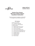
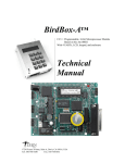
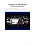
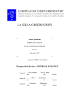
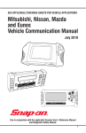
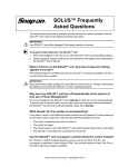
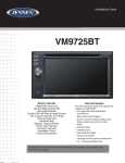
Chapter 3
Operations
This section explains how to begin using the scan tool’s basic setup and test functions. This
information is specific to Asian Import vehicles. For general scan tool functionality, see the
user’s manual appropriate to your diagnostic tool. Figure 3-1 outlines the general workflow of
using the VCS software.
TEST SAME VEHICLE
IN MEMORY?
YES
NO VEHICLE IN MEMORY?
NO
SELECT THE
SOFTWARE
IDENTIFY A
VEHICLE
SELECT A SYSTEM
CONNECT TO THE
VEHICLE
MAIN MENUS
CODE FUNCTIONS
AUTO CODE
READ
CUSTOM SETUP
MANUAL CODE
ENTRY
CODES & DATA
CLEAR CODES
FUNCTIONAL TESTS
HOW TO GET
CODES
PRINT CODES
Figure 3-1 Basic Asian Import scan tool test operation
i
NOTE:
The exact order of test operation steps may vary depending on the test vehicle. Be sure to
follow all on-screen instructions.
3.1 Selecting the Software
The first step in testing with the Vehicle Communication Software (VCS) is selecting the
correct software for your test vehicle.
Two types of screens display when you turn on your scan tool:
5
Chapter 3
Selecting the Software
• The initial menu (Figure 3-2) displays if you do not have a vehicle in memory.
• The Current Vehicle ID screen (Figure 3-3) displays if you have a vehicle in memory.
>GLOBAL OBDII
DOMESTIC
Asian
European
Figure 3-2 Initial menu
Current Vehicle Identification Is:
VEHICLE: 2003 ACURA RSX
ENGINE: 2.0L L4 MFI (K20A2)
Press Y: For Same Vehicle N: For New ID.
Figure 3-3 Sample Current Vehicle Identification screen
z
To select the software from the initial menu:
1. Select ASIAN (Figure 3-2).
The Year Range menu displays (Figure 3-4).
>1983 - 2005
Legacy Software
Figure 3-4 Year Range menu
2. Select the year range for the test vehicle.
The software loads for a moment and then the Software Confirmation screen displays
(Figure 3-5).
>ASIAN IMPORTS (1983-2005)
V 6.4
Figure 3-5 Sample Software Confirmation screen
3. Press Y to confirm the software.
The Manufacturer Selection menu displays (Figure 3-6).
SELECT MAKE:
>ACURA
CHRYSLER IMPORTS
DAIHATSU
Figure 3-6 Sample Manufacturer Selection menu (2002-2003)
6
z
To select the software from the Current Vehicle ID screen:
1. Press Y if you want to test the same vehicle, or press N if you want to test a different
vehicle (Figure 3-5).
If you pressed Y, the Connection Instructions screen or System Selection menu displays.
See “Selecting the Software” on page 5 or “Connecting to the Vehicle” on page 8 to
continue.
If you pressed N, the Software Confirmation screen displays (Figure 3-7).
>ASIAN IMPORTS (1983-2005)
V 6.4
Figure 3-7 Sample Software Confirmation screen
2. Press Y to select the software displayed and go to the Manufacturer Selection menu
(Figure 3-6). If you want to select different software, skip this step and go on to step 3.
3. Exit back to the initial menu and select the software as previously described.
z
To exit back to the initial menu from ASIAN IMPORTS (TO 2001) software (Legacy
Software):
1. Press Y.
The Manufacturer Selection menu displays (Figure 3-8).
SCROLL TO SELECT A MANUFACTURER
>ACURA (1986-2001)
CHRY IMPORTS (1984-2001)
DAIHATSU (1988-1992)
Figure 3-8 Sample Manufacturer Selection menu (to 2001)
2. Scroll to the end of the list and select EXIT THIS MENU.
The initial menu displays (Figure 3-2).
z
To exit back to the initial menu from ASIAN IMPORTS (1983-2005) software:
• Press N.
The initial menu displays (Figure 3-2).
3.2 Identifying a Vehicle
After you have selected the software, you are prompted to identify the test vehicle by entering
vehicle identification number (VIN) characters and answering questions.
i
NOTE:
Because of midyear manufacturing changes in engine computer systems, you should always
enter a new identification when you test a different vehicle, even when two vehicles are the
same year, model, and have the same engine and accessories installed.
7
Chapter 3
z
Selecting a System
To identify a vehicle:
1. From the Manufacturer Selection menu (Figure 3-8), select the vehicle manufacturer.
The first in a series of Vehicle Identification screens displays (Figure 3-9).
SELECT 10TH VIN CHARACTER
VIN: ---------3-----VEHICLE: 2003 ACURA
ENGINE:
Figure 3-9 Sample Vehicle Identification screen
2. Scroll and press Y to enter VIN characters, and press Y or N to answer any questions.
When you are finished, a Vehicle ID Confirmation screen displays (Figure 3-10).
VIN: ---N-2---3-----VEHICLE: 2003 ACURA NSX
ENGINE: 3.2L V6 MFI (C32B1)
PRESS Y TO CONTINUE. N FOR NEW ID.
Figure 3-10 Sample Vehicle ID Confirmation screen
3. Press Y if the vehicle ID is correct or press N to identify a different vehicle.
The System Selection menu or Connection Instruction screen displays.
3.3 Selecting a System
A System Selection menu prompts you to select which vehicle control system to test
(Figure 3-11). Menus vary by manufacturer and model. Refer to the manufacturer-specific
chapters of this manual for instructions on selecting a system to test.
SELECT SYSTEM:
>ENGINE
TRANSMISSION
ANTI-LOCK BRAKES
Figure 3-11 Sample System Selection menu
3.4 Connecting to the Vehicle
A Connection Instruction screen tells you how to connect the supplied vehicle test adapters to
the test vehicle you identified (Figure 3-12).
CONNECT OBDII ADAPTER WITH K2A TO 16-PIN
CONNECTOR UNDER GLOVEBOX.
NOTE!! CYCLE KEY OFF TO ON.
PRESS Y TO CONTINUE.
Figure 3-12 Sample Connection Instructions screen
8
Each test adapter plugs into a specific vehicle diagnostic connector and attaches to one end
of the data cable. The other end of the data cable attaches to the scan tool.
The following adapters are available to connect the scan tool to Asian Import vehicles. See the
manufacturer-specific chapters of this manual for connector locations.
Figure 3-13 MT2500-90 MULTI-1 adapter
Figure 3-14 MT2500-46 OBD-II adapter with
Personality Key™
Figure 3-15 MT2500-50 TOYOTA-1 adapter
Figure 3-16 MT2500-52 TOYOTA-2 adapter
MT2500-53 MAZDA-1 adapter
Figure 3-17 MT2500-40 NISSAN-1 adapter (12-pin)
Figure 3-18 MT2500-58 NISSAN-2 adapter (16-pin)
Figure 3-19 MT2500-77 HON-1 adapter
Figure 3-20 MT2500-51 HYUNDAI-2 adapter
Figure 3-21 MT2500-55 MITSU-1 adapter
9
Chapter 3
Connecting to the Vehicle
Figure 3-22 MT2500-43 Terminal Converters
Figure 3-23 MT2500-41 Ground adapter
Figure 3-24 CAN1B adapter
A
B
C
D
E
F
Figure 3-25 MT2500-42 MULTI-2 Asian adapter
A—Ground
B—Mazda & Ford (2E)
C—Isuzu & Geo with GM system (2D)
D—Subaru (2C)
E— Mazda & Ford (2B)
F— Special applications (2A)
z
To connect to a vehicle:
• Follow the on-screen instructions and press Y when you are finished.
The main menu displays (Figure 3-26).
MAIN MENU
>CODES & DATA MENU
FUNCTIONAL TESTS
ACTUATOR TESTS
CUSTOM SETUP
MOVIES
Figure 3-26 Sample main menu
10
3.5 Main Menu Selections
Depending on the vehicle, the following main menu options may be available:
• CODE FUNCTIONS lets you read and interpret electronic control module (ECM)
diagnostic trouble codes (DTCs).
• CODES & DATA lets you read input and output signals (switches, sensors, and
actuators). See the manufacturer-specific sections of the manual for specific information.
• CODES & DATA MENU lets you access a submenu of tests on OBD-II vehicles.
• FUNCTIONAL TESTS provides specific subsystem and component tests. Tests vary by
make and model, see the manufacturer-specific sections of the manual for specifics.
• ACTUATOR TESTS lets you check the operation of certain actuators, such as solenoid
valves and relays. Tests vary by make and model, see the manufacturer-specific sections
of the manual for specifics.
• CUSTOM SETUP lets you customize certain scan tool functions. See the manual for your
diagnostic tool for details.
• MOVIES lets you record and view data. See the manual for your diagnostic tool for
details.
3.6 Code Functions
Selecting CODE FUNCTIONS displays the Code Functions menu (Figure 3-27).
>AUTO CODE READ
HOW TO GET CODES
CLEAR CODES
PRINT CODES
MANUAL CODE ENTRY
REVIEW CODES
Figure 3-27 Sample Code Functions menu
Depending on the vehicle type, six primary CODE FUNCTIONS selections may be available:
• AUTO CODE READ reads all available electronic codes automatically (Figure 3-28).
• HOW TO GET CODES helps you to locate the test connectors or code lamps for getting
codes, and helps you identify the code type.
• CLEAR CODES clears (erases) trouble codes from the vehicle ECM memory.
• PRINT CODES prints selected trouble code definitions.
• MANUAL CODE ENTRY lets you read codes that can be identified by visual observation
of a flashing lamp (LED) and manually entering data into the scan tool (Figure 3-28).
• REVIEW CODES lets you review codes stored in scan tool memory, either through
automatic code reading or manual code entry.
11
Chapter 3
Code Functions
MAIN MENU
SELECT CODE
FUNCTIONS
AUTO CODE
READ?
YES
SELECT AUTO
CODE READ
YES
ACTIVATE VEHICLE
CODE OUTPUT
ACTIVATE VEHICLE
CODE OUTPUT
SCAN TOOL READS
AND TAGS CODES
NO
MANUAL CODE
ENTRY?
NO
READ CODES
SELECT
MANUAL CODE
OTHER TEST
FUNCTIONS?
TAG CODES
USE SCAN TOOL FOR
CODE DEFINITIONS
FIX THE
PROBLEM
CLEAR CODES
(RESET ECM)
RE-CHECK FOR
CODES
Figure 3-28 Basic Code Functions: Auto Code Read and Manual Code Entry
3.6.1 Reading Different Code Types
Depending on the vehicle, the diagnostic connector may have automatic code reading or you
may have to read codes by observing a flashing lamp (LEDs). After you enter the vehicle ID,
the scan tool tells you which type of system is on the vehicle you are testing. MANUAL CODE
ENTRY is used when the AUTO CODE READ selection is not available or when you prefer to
enter a code manually.
For vehicles with diagnostic connectors that have automatic code reading, connection
instructions for code reading display at the end of the vehicle ID sequence. Instructions for
activating flash codes are available by selecting HOW TO GET CODES (“How to Get Codes”
on page 15).
Flash Codes
Different types of code pulse patterns are used by different manufacturers for different
models. When a vehicle has indicator lamps (LEDs) that flash trouble codes, the scan tool
gives you the code type used for the vehicle you are testing and key words to describe the
type of code flashing pattern.
Five general code patterns are used:
• Straight Count—flashes the lamp or LED the number of times equal to the trouble code
with a noticeable pause between multiple codes.
12
For example, eight equal flashes is Code 8.
• Tens/Ones—flashes a 2-digit trouble code with a noticeable pause between each digit.
The first set of flashes is the 10s digit; the second set of flashes is the 1s digit.
For example, FLASH-FLASH pause FLASH-FLASH-FLASH is Code 23.
• Long/Short—flashes a 2-digit trouble code with the 10s digit pulses staying on longer
than the 1s digit pulses.
For example, LONG-LONG pause SHORT-SHORT-SHORT is Code 23.
• Main code and Sub-code—main code will flash first, then pause. Sub-code will follow.
• 4-LED—turns on one-to-four LEDs to display a binary code. The LEDs stay on until the
code is cleared.
• 2-LED—flashes a 2-digit trouble code with the 10s digit flashed on one LED and the 1s
digit flashed on the other LED.
3.6.2 Automatic Code Reading
Selecting AUTO CODE READ from the Code Functions menu displays a screen like
Figure 3-29.
INCOMING CODES:
WAITING FOR CODES
IF NO RESPONSE, TRY
INDUCING A CODE TO CHECK CODE GATHERING.
***END OF LIST***
Figure 3-29 Incoming Codes screen
If multiple codes are received, the scan tool continues to add to the list. Scroll to view the
numbers and titles of all codes. Code numbers appear on the top line in the order in which the
ECM transmits them (Figure 3-30).
INCOMING CODES: 11 14
SCROLL & PRESS Y TO DELETE CLEARED CODES.
>11 INTAKE AIR TEMP CIRCUIT PROBLEM
14 ATMOSPHERIC PRESSURE SENSOR CIRCUIT
Figure 3-30 Sample Auto Code Read screen
LEDs flash simultaneously with the codes as they are received by the scan tool.
i
NOTE:
Some vehicles transmit codes very slowly. Allow several seconds after receiving any code to
ensure that no more codes follow.
After you repair a problem or clear codes from the vehicle, the code numbers next to
INCOMING CODES are removed. The individual lines with code numbers and titles remain on
the AUTO CODE READ screen and in REVIEW CODES until you remove them manually.
z
To delete cleared codes:
1. Scroll to the line with the code that you want to remove.
2. Press Y to clear the code.
13
Chapter 3
Code Functions
The code number and title are removed from the list. If the code has not been cleared from
the ECM, the number remains on the top line.
3.6.3 Clearing Codes
The CLEAR CODES selection is available from the Code Functions menu after codes have
been received. Selecting CLEAR CODES provides specific vehicle information for clearing
ECM trouble codes (Figure 3-31).
TO CLEAR CODES, DISCONNECT BATTERY
GROUND CABLE. DEPRESS & HOLD BRAKE
PEDAL FOR AT LEAST 5 SECONDS. RECONNECT
BATTERY & RECHECK FOR CODES. [N TO EXIT]
Figure 3-31 Clear Codes screen
Trouble codes are often cleared by removing the battery ground cable or removing a fuse. In
some cases however, the AUTO CODE READ function lets the scan tool clear codes
automatically (Figure 3-32).
CLEAR CODES FROM VEHICLE MEMORY:
ARE YOU SURE? PRESS Y OR N.
Figure 3-32 Clear Codes Confirmation screen
If you press Y, the scan tool displays the following message (Figure 3-33).
CLEAR CODES FROM VEHICLE MEMORY:
CLEARING CODES . . . WAIT
PRESS N TO RESUME.
Figure 3-33 Clearing Codes screen
When all codes are erased, the display changes to the following (Figure 3-34).
CLEAR CODES FROM VEHICLE MEMORY:
CODES ERASED FROM VEHICLE MEMORY
PRESS N TO RESUME.
Figure 3-34 Codes Cleared screen
i
14
NOTE:
If the vehicle ECM does not receive the code-clearing command, the CLEARING CODES...
WAIT message stays on the screen indefinitely.
3.6.4 Printing Codes
See the manual for your diagnostic tool for information about setting up a printer.
3.6.5 Manual Code Entry
If you are testing a vehicle that can only display codes manually, you receive connection
instructions from the Connection Instruction screen (Figure 3-35).
MANUAL CODES ONLY. FOR CODE LIST,
USE POWER PAC, OR USE MULTI-1 WITH
GROUND EXTENSION & EITHER POWER CABLE.
PRESS Y TO CONTINUE.
Figure 3-35 Sample Connection Instruction screen for manual codes only
Select HOW TO GET CODES from the Code Function menu to see on-screen instructions
about reading manual codes from the vehicle you are testing.
3.6.6 How to Get Codes
Selecting HOW TO GET CODES gives instructions for observing codes manually or
automatically, depending on the vehicle (Figure 3-36). The on-screen instructions are
supplemented in the manufacturer-specific chapters of this manual.
FIND ECU BEHIND LEFT KICKPANEL.
TURN ECU SWITCH “ON”. SEE MANUAL.
RED LED PULSES TENS DIGIT, GREEN PULSES
ONES. CODE TYPE 07a.
Figure 3-36 Sample How to Get Codes screen
3.6.7 Reviewing Codes
The REVIEW CODES selection is only available on the Code Functions menu after the scan
tool has received codes from a vehicle, either automatically or manually. Selecting REVIEW
CODES displays a screen similar to Figure 3-37. Scroll to view all codes.
CODE SUMMARY: 12 22 23 31 55
*****CODE DEFINITIONS*****
12 AIRFLOW METER CKT OPEN OR SHORTED
22 FUEL PUMP CIRCUIT PROBLEM
Figure 3-37 Sample Review Codes screen
15
Chapter 3
Demonstration Programs
3.7 Demonstration Programs
The Asian Import VCS contains a program that demonstrates many of the scan tool’s test
capabilities without actually connecting to a vehicle. A sample vehicle ID and mock test results
are provided to familiarize you with scan tool menus and basic operations.
i
NOTE:
The DEMO selection appears at the end of the list of available manufacturers for 2001 and
earlier vehicles only.
z
To access the demonstration program:
1. Select the software as described in “Selecting the Software” on page 5.
The Manufacturer Selection menu displays (Figure 3-38).
SCROLL TO SELECT A MANUFACTURER
>TOYOTA
OBDII GENERIC
DEMO
Figure 3-38 Sample Manufacturer Selection menu
2. Select DEMO.
A Vehicle Identification screen displays with “DEMO” in the first line, indicating that you
are in the demonstration program (Figure 3-39).
SELECT 10TH VIN CHARACTER
VIN: ---------V-----VEHICLE:
ENGINE:
DEMO
Figure 3-39 Asian demo Vehicle Identification screen
3. Keep pressing Y to choose the defaults until the System Selection menu displays
(Figure 3-40).
SELECT SYSTEM:
>ENGINE
TRANSMISSION
ANTI-LOCK BRAKES
Figure 3-40 System Selection menu
i
16
NOTE:
If Troubleshooter software is installed, it will be accessible for demonstration purposes. Make
sure you select the system that matches the Troubleshooter software. For example, if you
have a Transmission Troubleshooter installed, make sure to select TRANSMISSION from the
System Selection menu.