1
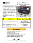
Vulcan Heater Congratulations for choosing VULCAN electric heating system. It is loaded with 37,000 BTU’s of heat power, offers wide range of air flows and precise temperature controls. It features individually controlled heating elements, variable speed blower and programmable temperature controller. 25’ thermocouple probe can measure containment air or material temperature for efficient and safe heat control. The intended use of the Vulcan is temporary heat for construction sites and restoration projects to shorten structural drying. Vulcan delivers the heat safely and efficiently where you need it... When you need it... CAUTION CAUTION Caution – High temperature, keep electrical cords, drapery and other furnishings at least 3 Ft (0.9 m) from the exhaust of the heater and from the side and rear. CAUTION RISK OF ELECTRIC SHOCK DO NOT OPEN NO USER-SERVICEABLE PARTS INSIDE Attention - haute température, garder les cordons électriques, les draps(couvertures) et d'autres fournitures à au moins 3 pi (0,9 m) de l'échappement de l'appareil de chauffage sur le côté et en arrière. Prudence Risque d'électrocution Ne pas ouvrir Aucune pièce utilisable à l'intérieur WARNING This equipment to be operated only by trained personnel. Do not use with combustible or explosive material. Do not expose to water or rain. Connect only to grounded outlet with GFCI device. Disconnect power for cleaning and servicing. Cet équipement à être exploité uniquement par du personnel qualifié. N'utilisez pas avec des matériaux inflammables ou explosifs. N'exposez pas à l'eau ou à la pluie. Se connecter uniquement à la sortie avec dispositif de GFCI. Coupez l'alimentation pour le nettoyage et l'entretien. 1 IMPORTANT INSTRUCTIONS Read all instructions before using the heater. CAUTION Connect ONLY to outlets that are properly grounded and have over-current protection. Use power cords rated at 250 VAC/50 Amp with minimum of 3-#6 and 1-#8 conductors. Do not operate heater with damaged cord or plug, after a heater malfunction, or has been dropped or damaged in any manner. . Use EXTREME caution when operating the heating unit around children and anytime the unit is left unattended. To disconnect heater, turn all heating elements off, cool it down and turn blower off. Unplug the cord. Place cord out of the path of foot traffic to avoid trip hazard. Do not run the power cord under carpets, rugs or furniture. Do not use outdoors. Use only in DRY location and avoid placement where it could fall into water. The heater has hot and arcing or sparking parts inside. Avoid operating in an environment with flammable liquids, gas or paint. Do not use to exhaust combustible or explosive gases or operate in hazardous atmosphere. Do NOT operate the Vulcan without air filter. Do not insert or allow foreign objects to enter intake or outlet openings as this may cause electrical shock or fire or damage heater. Heater will be hot during operation, use handles when moving. To prevent possible FIRE, DO NOT BLOCK OFF INTAKE OR EXHAUST. The hot air exhaust should not be located less then 3 feet from wall and soft goods, i.e. clothing, linens, pillows, paper. The sides of the unit should be at least one foot away from the wall or soft goods. Do NOT cover an operating machine. The appliance is not to be used by persons (including children) with reduced physical, sensory or mental capabilities, or lack of experience and knowledge, unless they have been given supervision or instruction. Children being supervised not to play with the appliance. Use the Vulcan only as prescribed, any other use may cause fire, shock or injury to persons. Always unplug unit when not in use. See proper shutdown procedure in this manual. SAVE THESE INSTRUCTIONS WARNING “GROUNDING INSTRUCTIONS - This appliance must be grounded. In the event of a malfunction or breakdown, grounding will reduce the risk of electric shock by providing a path of least resistance for electric current. This appliance is equipped with a cord having an appliance-grounding conductor and a grounding plug. The plug must be plugged into an appropriate outlet that is installed and grounded in accordance with all local codes and ordinances.” “WARNING - Improper connection of the appliance-grounding conductor can result in a risk of electric shock. Check with a qualified electrician or service representative if you are in doubt whether the appliance is properly grounded. Do not modify the plug provided with the appliance; if it will not fit the outlet, have a proper outlet installed by a qualified technician.” AVERTISSEMENT: "INSTRUCTIONS DE MISE À LA TERRE - Cet appareil doit être mis à la terre. En cas de défaillance ou de panne, la terre réduira le risque de choc électrique en fournissant un chemin de moindre résistance au courant électrique. Cet appareil est équipé d'un cordon comportant un conducteur de l 'appareil à la terre et une prise de mise à la terre. La prise de mise à la terre doit être branchée dans une prise électrique appropriée, installée et mise à la terre conformément aux codes et règlements locaux." "ATTENTION - Une connexion incorrecte du conducteur de l 'appareil à la terre peut entraîner un risque de choc électrique. Vérifier avec un électricien qualifié ou un représentant de service si vous êtes dans le doute si l'appareil est correctement mise à la terre. Ne pas modifier la fiche fournie avec l'appareil;. si elle n'entre pas dans la prise, faites installer une prise adéquate par un technicien qualifié." 2 SPECIFICATIONS Table of Contents Introduction ........................................... 1 MODEL: OVH-230 Safety Instructions ................................ 2 Power Supply: 230VAC/60Hz/1 phase 50 amp supply - can operate all 6 heating elements, 50 amp load, 37,000 BTU output 30 amp supply - can operate up to 3 heating elements, 29 amp load, 20,500 BTU output. Note: Can operate on 208VAC at lower heat output and lower airflow. Blower Motor: 230VAC/60 Hz/1.13 amps, thermally protected, 950 cfm free air flow. Specifications ....................................... 3 Parts List............................................... 4 Operations Overview ............................ 4 Controls ................................................ 5 Operating Instructions........................... 6 Maintenance ......................................... 7 Air flow controls: Blower with speed controller, adjustable from 100 to 475 CFM (with MERV 11 filter in place). Trouble Shooting .................................. 7 Wiring Diagram ...............................8 & 9 Temp Control: - High temperature limit switch set at 160° F shut off and 135° F automatic r e s et . - Temperature Controller with adjustable set tings from 0° to 160° F with 25 ft thermo couple type K for monitoring and controlling temperature in remote area. Warranty ............................................. 11 Safety Shutoff: Loss of air flow and/or internal heater temperature above 180° F will shut off all active heating elements. Heating Elements: Industrial, tubular, finned de s i g n , 3 - 2100W.(30 amp service) and 3 - 1700W at 230 VAC service Filter: Pleated media MERV 11, 65% efficiency, 12”x12”x2”. Housing: Aluminum/galvanized metal, size 11”w x 29 3/4”l.x18”h with casters Dual insulated wall around heating elements; recessed control panel; 2 soft carrying handles. Duct Connections: Intake: 10” diameter connection . Outlet: 10” diameter ring. Maximum ambient temperature: 122° F (50°C) Operation: Suitable for indoors, DRY location only. Tested by TUV lab to comply with UL 1278 and CSA / IEC 60635-1 & -2 electrical safety standards. The heater is NEC compliant. 3 PARTS LIST ........................... PART # Introduction The manual is a guide for safe operation and maintenance of the Vulcan unit. Please read and understand this manual completely before operating and installing the heating unit on a job. Vulcan 37K 230V ...................... OHV-230 Range Adapter 8’ 50 amp 125/250 ....... EDP50R Dryer Adapter 8’ 30 amp 125/250 ........ EDP30D Pleat Filter 12”x12”x2” .......................... OPF1212 Quick Clamp, 10”..................................... QCW12 Flexible Duct, 10”x25’ ..............................OAD10 Thermocouple K , 25 ft ………………………..RTS12 Vulcan Operation Overview Vulcan delivers up to 37,000 BTU and 400 cfm of air flow at temperatures from ambient to 160° F. The heater outlet can be ducted to deliver heat where needed. The air intake could be open to ambient air or ducted from a dehumidifier. Options: Range Adapter 15’ 125/250/50 amp .... EDP50/1 Dryer Adapter 15’ 125/250/30 amp ..... EDP30D Thermocouple K , 3 ft ............................... RTS12 At air flow of 350 cfm, operating with all 6 heaters, the temperature rise at 350 CFM is 95° F above the ambient air. When operating on 30 amp circuit with 3 heaters, the temperature rise is 55° F. At lower air flow, the heat rise will be higher. At 475 CFM, the heat rise is 75° F with 6 elements on. Vulcan is designed for indoor use only and it is important to locate heater in dry, safe location. Heater exhaust must be 3 feet or more from a wall or any soft material. When ducting hot air to a remote area, using shorter duct reduces heat losses. Please read Safety warnings before starting to operate your new Vulcan. Unit may be operated in horizontal or upright position with exhaust aiming up. Do NOT lay unit on air intake side or block the outlet. Heater has to be plugged in 230 VAC power supply equipped with over-current protection. The heater unit blower has to be running before the safety interlock circuit enables the heater elements to be turned on. Depending on the 30 or 50 amp power supply, 3 or 6 heating elements can be selected. Since there are many variables from project to project, we recommend to set your air flow first and then start to turn the heating elements on. Depending on your ambient temperature, selected airflow and required temperature rise, the number of operating heating elements will vary. Vulcan offers maximum versatility with variable airflow and 6 heating elements which can be individually turned on as needed. After manually setting the air flow and number of heating elements, the heater temperature could be regulated in MAN (Manual) or AUTO mode. In MAN, the High temperature switch is set to shut off heating elements when internal heater temperature is 160º F and restart at 135º F. In AUTO mode the Temperature Controller measures remote air or material temperature by a 25 4 Temperature Controller and compared with selected Set Point (160 F maximum). Temperature Controller automatically turns selected heating elements on and off to maintain the set point. Air Flow Control: figure 1, #1 The air flow is controlled by changing speed of the blower. Turn a control knob from OFF to anywhere on the dial and check that AIRFLOW light turns ON. The Safety circuit protects the unit from overheating. If heater looses a minimum required air flow all the heaters will shut down until the airflow is restored. Also, if internal heater temperature reaches 180º F, the safety thermo switch TS-1 shuts the heating elements down and restarts automatically at 150° F. Hour Meter: figure 1, #2 The digital hour meter measures the cumulative time the unit is running to tenths of an hour. It stores and displays the total time when the unit is disconnected from power supply. Electrical Requirements: Vulcan unit requires Temperature controller: figure 1, #3 230VAC/ 1 Phase power source with over-current protection rated at 50 amp maximum. It can be dryer/range outlets, generator or hardwired into electrical panel by a certified electrician. The amperage draw will depend on the number of elements engaged. Each element draws about 8 amps. For maximum heat gain, use all 6 heating elements. Note: Heater can operate on 208VAC at reduced heat output. Temperature Controller is programmed to maintain user selected set point temperature when AUTO mode is selected and remote thermocouple is connected to thermocouple plug on the control panel. Place the sensor end in containment area to monitor air or materials temperature to prevent overheating delicate parts of structure. Operator’s Controls (figure 1) Status Lights: figure 1 #1 Blower speed controller with OFF and Max-Low provides adjustable airflow settings. #2 Hour meter displays the hours the unit operates. #3 Temperature Controller displays measured temperature, Set Point and provides automatic ON/OFF heaters control. #4 Thermocouple connector for K-type sensor #5 Temperature Control mode selector switch with MAN /AUTO positions. #6 Heaters switches 1 true 6 - ON/OFF switch with internal light. Lights illuminate as each heating element is activated. If the element is not activated, the switch light will not be illuminated. POWER - Red light indicates power to the unit is On. AIRFLOW - Amber light indicates blower is operating and the air flow switch is closed. SAFETY– Amber light indicates the air flow is safe and the heater internal temperature is below 180° F. HEATER ELEMENTS - Each heating element switch illuminates when switched ON and active. AIRFLOW figure 1 5 When SP temperature is reached, Temperature Controller will turn heating elements Off and automatically restart when temperature drops 15° F below the SP. Change your SP as needed at any time. OPERATING INSTRUCTIONS Unpacking: Check unit for damage. Don’t operate when damaged in any way. Operation: 1. Inspect Vulcan and the power cord for any damages before using. Do not use the system or the cords if damaged. Read Caution statement. 2. Locate the unit in safe DRY area. See WARNINGS and CAUTIONS on page 2. 3. Turn all heater switches OFF and Temperature Control switch to MAN. 4. Plug your unit into 230VAC/1 phase, 30 or 50 amp power supply. POWER light will come ON. Note: Use only power source with ground and over-current protection. The power cord should be rated for 250VAC/50 amp service and have minimum of 3-#6 and 1-#8 conductors. 5. Turn AIRFLOW controller knob from OFF to your required speed and the AIRFLOW status light will turn ON. 6. When AIRFLOW light is on and internal heater temperature is less than 180° F, the SAFETY light will turn ON. 7. Turn ON the individual heating elements, starting with #1. For 30 amp power supply only #1, 2 & 3 elements (20,500 BTU) can be ON. For 50 amps, all 6 heaters (37,000 BTU) can be turned ON. After the heater stabilizes at your required temperature, check the operation of the heating elements. If the Temperature Controller is frequently turning the heaters OFF/ON, reduce the number of active heaters or increase the air flow. Shut Down Procedure The heat energy stored in the heating elements could heat up the outer surface of the unit if it is shut down without any cooling down period. To prevent this and to maximize the life of the heating elements, follow this procedure: 1) Switch all heating elements to OFF position 2) Allow blower to run for 2 minutes or until air flow has cooled 3) Switch blower to OFF position 4) Disconnect cords and store the unit Operation Tips: Each heating element operating on 230 Vac, draws 8 amps and supplies about 6,150 BTU’s. Elements #1,2,3 are 2100 W to maximize heat at 30 amp supply. Manual Temperature Control: Temperature Control switch should be in MAN position. To regulate the heater temp., activate only number of heating elements required for the heat rise. Increasing airflow will decrease the exhaust air temperature. The High temperature switch TS-2, will turn the heaters Off and On between 160° and 135° F. To minimize the cycling , balance the airflow and the number of Internal heater temperature is limited to 160° F. When this high limit is reached, thermo switch TS-2 turns all active heaters off and automatically restarts at 135° F. Note: The exhausted air temp. may be considerably higher then 160°F. active heaters. Watch the heater switches lights to see the ON/OFF operation. The temperature Safety switch will turn the heaters Off and On between 180° and 150° F. This is a safety cutoff and heater should not operate this hot. When safety switch shuts the heaters down, the SAFETY light also turns off. If the 160°F thermo switch is frequently turning the heaters OFF/ON, reduce the number of heating elements or increase the air flow to stay below 160° F. Auto Temperature Control: Switch temperature control switch to AUTO position. On Temperature Controller, use up/down arrows to set the desired temperature Set Point (SP) up to 160° F. Locate the thermocouple end in measured area or targeted material. The Temperature Controller will display the measured temperature and selected set point SP. When internal heater temperature reaches 160 F limit, the exhaust air temperature would be around 180 F. Take this in consideration when ducting hot air to a remote containment area and setting Temp. Controller SP. 6 Problem : Both contactors are energized, but some heater switches do not illuminate when selected. Note: Contactor #1 controls heater elements 1, 2 and 3; Contactor #2 controls heater elements 4, 5 and 6. Test: Turn ON one heater at the time to check each heater circuit. The heater switch will illuminate when heater is turned on and functioning. Check the heater output for the temperature rise. Maintenance: The blower and motor do not require any maintenance when the heater is operated with MERV 11 filter in place. Replace filter as needed. If filter becomes clogged with debris it will reduce the performance of the unit. ALWAYS UNPLUG FROM POWER BEFORE OPENING THE UNIT. If selected heater switch does not illuminate, problem could be: Faulty heater switch or heating element Trouble Shooting This guide may identify easy to correct problems in Vulcan operation and does not require opening the unit. Only qualified maintenance person should replace internal heater parts. Removable control panel provides easy access to panel mounted components. The heating elements and blower motor can be accessed by removing cover panels on the bottom. Problem — Heater is frequently cycling ON and OFF as the High temperature switch operates between 160° and 135° F. Watch heaters switch lights for cycling frequency. Reduce number of heating elements turned ON. Increase air flow Check for obstacles on suction and discharge side. This could be dirty filter or a long ducting. Note: Start testing with Temperature Control switch in MAN position. Problem - POWER (red) light does not come on when plugged in 230 Vac/1 ph power. Check the power supply source and the extension cords are in good working condition and providing 230V . Temperature Controller in AUTO mode Temperature Controller (TC) will display temperature measured by the thermocouple all the time, but only in AUTO mode will it use the measured temperature and the set point (SP) temperature to control the heaters. When SP is reached, the heaters are turned off till temperature drops 15° F below SP, then turned on again. The SP temperature can be adjusted with Up/Down arrows at any time. Problem - Blower is running, but AIRFLOW light is off Increase the blower speed until the AIRFLOW light comes on - if no AIRFLOW light comes on and contactors do not energize ( loud click), problem could be: Faulty air flow switch NOTE: The programming functions on Temperature Controller are locked to prevent unauthorized program changes. See programming section of the manual to unlock, reset or change the program. Problem - Blower is running, AIRFLOW light is on but SAFETY light is off while heater is cool. TS-1 Safety thermo switch needs to be checked. It is set to open at 180° F and close again at 150 F. Problem - Heater works when Temperature Control switch is in MAN but heaters turn off when TC controls the heaters in AUTO.. Problem - Blower is running, AIRFLOW and SAFETY lights are on, but contactors do not click on (heater switches do not illuminate when switched ON). The thermocouple must be plugged in for TC to operate. If Temperature Controller display reads NO CONT., thermocouple could be faulty. If heater is hot, let the airflow cool it down. High limit thermo switch TS-2 is set to open at 160° F and reset automatically at 135 F. One or both contactors could be faulty. The SP temperature must be set above the temperature measured by the thermocouple for heaters to turn on - use Up/Down arrows to change the SP. NOTE: High temp. limit switch shuts down heater at 160 F internal temperature even if SP calls for more heat. 7 8 9 LIMITED WARRANTY REGISTRATION The undersigned has read and understood the below Warranty, Limitation of Warranty and Limitation of Remedy PRODUCT: Vulcan 37K SERIAL #___________________ PURCHASED FROM_______________________________DATE_________________ CUSTOMER: COMPANY____________________________________________________________________PHONE_______________ STREET____________________________________________________________________________________________ CITY________________________________________STATE___________________ZIP CODE_____________________ BY_______________________________________________DATE_____________________________________________ SEND TO: OMNITEC DESIGN, INC., 4640 Campus Place #110, Mukilteo, WA 98275 ----------------------------------------------------------------------------------------------- KEEP THIS BOTTOM PORTION FOR YOUR RECORDS. DATE PURCHASED___________ OMNITEC DESIGN, INC. LIMITED WARRANTY Omnitec Design, Inc. warrants that all products, component parts and accessories, excluding filters, will be for a period of twelve (12) months from the date of purchase, be free from defects in material and workmanship under normal use and service. THE PURCHASER’S SOLE AND EXCLUSIVE REMEDY UNDER THIS WARRANTY IS LIMITED TO THE REPAIR OR REPLACEMENT OF DEFECTIVE PARTS F.O.B., OMNITEC DESIGN, INC., 4640 Campus Place #110, Mukilteo, WA 98275; www.omnitecdesign.com In order to keep this in effect, the purchaser must (i) return this signed LIMITED WARRANTY to Omnitec Design within 30 days of purchase date, (ii) have promptly informed Omnitec Design’s Customer Service of any defects and (iii) properly used and maintained the Product. This warranty does not cover normal wear and tear or defects due to (i) improper or negligent handling or unauthorized modifications; (ii) defective or improper premises, chemical or electrical influences; or (iii) weather or other influences of nature. LIMITATIONS OF WARRANTY THIS WARRANTY IS EXPRESSLY IN LIEU OF ANY AND ALL OTHER WARRANTIES AND OBLIGATIONS OF OMNITEC DESIGN OR ITS SUPPLIERS, EXPRESSED OR IMPLIED, AND OMNITEC DESIGN EXPRESSLY DISCLAIMS ANY WARRANTY OF MERCHANTABILITY OR FITNESS FOR ANY PARTICULAR PURPOSE. LIMITATION OF REMEDY Under no circumstance shall Omnitec Design or any supplier of Omnitec Design be liable for any loss or damage, including, but not limited to, loss or damage arising out of the failure of the Products to operate for any period of time, inconvenience, the use of rental or replacement equipment, loss of profits or other economic loss, or general, direct, special, indirect, incidental or consequential damages or property damages. PRODUCT SUITABILITY Many states and localities have codes and regulations governing sales, construction, installation, and/or use of products for certain purposes, which may vary from those in neighboring areas. While Omnitec Design attempts to assure that its Products comply with such codes, it cannot guarantee compliance, and cannot be responsible for how the Products are installed or used. Omnitec Design recommends that before purchasing and using a Product, purchasers review the Product application, and federal, state and local regulations, to be sure that the Products, installation and use will comply with them. 10