1
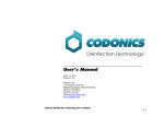
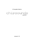
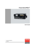
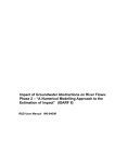
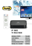
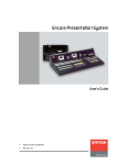
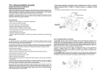
INSTRUCTION MANUAL 1 IMPORTANT SAFETY INSTRUCTIONS • • • • • • • • • Read all the instructions before use. Do not position the synthesizer in direct sunlight or in areas subject to heat, moisture, dust, cold or vibration. Clean the synthesizer with a damp cloth while switched off. Do not use solvents or abrasive cleaners. Do not apply excessive force to any of the switches and knobs. Switch off and unplug when not is use. The synthesizer is capable of producing audio levels that could cause hearing loss. Do not use the synthesizer at high volume levels for extended periods of time, especially when using headphones. If you experience ringing in your ears after use, consult an audiologist. The EEPROM that stores patches and user waves has a life of 100,000 write/erase cycles. You may find it becomes unreliable after this. Only use the power supply provided. Do not hold the power supply by the cable when plugging and unplugging it into the synthesizer, always hold it by the connector. Do not stand on it. Do not attempt to service the synthesizer. Contact Soulsby Synthesizers if your synthesizer stops working. Introduction Thank you for purchasing the Atmegatron by Soulsby Synthesizers. We feel certain that it will provide you with a whole world of new sounds and creativity. The Atmegatron is designed for performers, programmers and hackers. The controls have been designed to be intuitive; you will soon find yourself tweaking sounds even if you have never programmed a synthesizer before. There are no complex menu systems or sequences of button presses. The first section of this manual provides you with all the information for basic operation of the Atmegatron. The next chapters go through each feature in detail. Following that there is an overview of advanced functions, as well as tables of certain sound parameters. Atmegatron parameters such as function names or physical connections are highlighted in red. Programming and debugging tips are marked with a thumbs-up symbol. Please take time to visit soulsbysynths.com where you can find more information, patches and the Atmegatron Librarian software. 2 Contents Introduction ................................................................................................................................................................................................... 1 Contents ......................................................................................................................................................................................................... 2 Connections .................................................................................................................................................................................................. 3 Live Setup ........................................................................................................................................................................................................................................... 3 Studio Setup....................................................................................................................................................................................................................................... 3 Top Panel ............................................................................................................................................................................................................................................ 4 Back Panel .......................................................................................................................................................................................................................................... 4 Basic Operation .......................................................................................................................................................................................... 5 Overview .............................................................................................................................................................................................................................................. 5 Function and Value Dials ............................................................................................................................................................................................................ 5 Digital Controls ................................................................................................................................................................................................................................. 7 Analogue Controls .......................................................................................................................................................................................................................... 7 Functions ....................................................................................................................................................................................................... 8 Waveform Select ............................................................................................................................................................................................................................. 8 Filter Type ........................................................................................................................................................................................................................................... 8 Filter/Pitch Envelope ..................................................................................................................................................................................................................... 9 Amplitude Envelope .................................................................................................................................................................................................................... 10 LFO (Low Frequency Oscillator) ............................................................................................................................................................................................ 10 Arpeggiator ....................................................................................................................................................................................................................................... 11 Portamento....................................................................................................................................................................................................................................... 12 Wave Crusher ................................................................................................................................................................................................................................. 12 Load/Save Patch ............................................................................................................................................................................................................................ 13 Digital Controls ......................................................................................................................................................................................... 14 Filter Cutoff ....................................................................................................................................................................................................................................... 14 Filter Resonance ........................................................................................................................................................................................................................... 14 Filter Envelope ............................................................................................................................................................................................................................... 14 Filter LFO........................................................................................................................................................................................................................................... 14 Amplitude LFO................................................................................................................................................................................................................................ 14 Distortion Level .............................................................................................................................................................................................................................. 15 Pitch Envelope ................................................................................................................................................................................................................................ 15 Pitch LFO ........................................................................................................................................................................................................................................... 15 Pulse Width LFO ............................................................................................................................................................................................................................ 15 Phase LFO ........................................................................................................................................................................................................................................ 16 Analogue Controls .................................................................................................................................................................................. 17 Volume................................................................................................................................................................................................................................................ 17 Bass Boost ........................................................................................................................................................................................................................................ 17 Advanced Functions............................................................................................................................................................................... 18 SysEx Write Patch ........................................................................................................................................................................................................................ 18 Enable SysEx Read ...................................................................................................................................................................................................................... 18 Enable User Waveform Mode................................................................................................................................................................................................. 18 SysEx Write Memory Bank ...................................................................................................................................................................................................... 19 Hacking........................................................................................................................................................................................................ 20 System Diagram ...................................................................................................................................................................................... 21 Glossary ....................................................................................................................................................................................................... 21 Audio Waveforms................................................................................................................................................................................... 22 Filter Types................................................................................................................................................................................................ 23 LFO Waveforms ...................................................................................................................................................................................... 24 Clock Division Rates ............................................................................................................................................................................. 25 Arpeggiator Patterns ........................................................................................................................................................................... 26 Wave Crusher Presets ........................................................................................................................................................................ 27 MIDI Implementation Chart .............................................................................................................................................................. 28 Patch Sheets ............................................................................................................................................................................................. 29 Warranty ..................................................................................................................................................................................................... 32 3 Connections iáîÉ=pÉíìé= 12V power hifi / adapter keyboard amp MIDI cable MIDI controller keyboard MIDI out = píìÇáç=pÉíìé= If your MIDI interface has multiple MIDI ports, connect the MIDI controller to a different port from the Atmegatron. If it doesn’t, remove the MIDI cable connected to the MIDI out of the Atmegatron and connect to the MIDI controller. This will need to be reconnected when using the Librarian software. audio/MIDI interface USB or Firewire cable line/instrument input 1/4” mono jack cable MIDI MIDI out in MIDI cable headphones 3.5mm plug computer 12V power adapter = = 4 qçé=m~åÉä= Digital controls Red/Green mode toggle for digital controls Analogue controls Function Function dial knob Value dial Value knob = _~Åâ=m~åÉä= Audio MIDI 12V MIDI Output Receive PSU output light Programmer MIDI/ MIDI Headphones header Programmer input switch 5 Basic Operation lîÉêîáÉï= The Atmegatron is a monophonic 8-bit synthesizer. Monophonic means that it can only play one note at a time. This means it is ideal for basses and leads. In addition, a unique form of polyphony can be simulated using the Arpeggiator (see page 11 for information on how to do this). 8-bit means that the sound is calculated digitally using 8-bit values (integer numbers between 0 and 255). This is how home computers worked in the 1980s and the Atmegatron excels at creating these kinds of sounds. However the processor is far more powerful that those in 80s home computers, so it is packed with features never possible in that era. The controls of the Atmegatron are divided into 3 areas: the function and value dials, the digital controls and analogue controls. cìåÅíáçå=~åÇ=s~äìÉ=aá~äë= pÉäÉÅíáåÖ=ÑìåÅíáçåë=~åÇ=ëÉííáåÖ=î~äìÉë= The function dial is on the left and the value dial is on the right. By looking at the position of the lit red LED and the corresponding symbol on the dial, you can see what the current function is, and it’s value. In this example, the function is set to Filter Type and the value is set to 9 (low shelf filter) as shown by the outer ring on the value dial. To change the Filter Type, turn the value knob and the circular LED will change position. For example if you want to change the Filter Type to a low pass filter (LPF), turn the knob until the LED next to 1 on the inner dial is lit. There is a symbol representing a low pass filter on the outer ring of the value dial. The full list of filter types and their corresponding symbols can be found on page 23. 6 In this example we are going to change the Portamento time (the time it takes for the pitch to glide from one note to another). Turn the function knob to the Portamento symbol and then turn the value knob to the desired value. In the example below it has been set to 5 (the portamento time is longer at higher values). You may notice that all the LEDs from 0 to 6 are lit, as opposed to just 6 (in the previous example). Functions that have a scale (rather than a set value) are shown like this. These parameters are: all Filter/Pitch Envelope and Amplitude Envelope parameters and Portamento. RÉÇ=~åÇ=ÖêÉÉå=ãçÇÉë= The function knob can be pushed in and when you do this, it changes from glowing red to green (and vice versa). Each function on the function dial has a green mode, which is activated by pushing the knob. For example turn the function knob so that Waveform Select is highlighted. Play a few notes. Now press the knob on the function dial, so it glows green. Play a few more notes and you will hear that the sound is different. This is because you are now in the green bank of waveforms. If you turn the value dial you can hear all the different waveforms in the green bank. 7 pçìåÇ=íÉëí= When the value knob is pushed in, the Atmegatron plays a test note. When you twist the knob whilst it is pressed in, you can change the pitch of the note. This is useful for programming sounds when you don’t have a MIDI controller keyboard attached. iç~ÇáåÖ=~åÇ=ë~îáåÖ=é~íÅÜÉë= To load or save a sound, turn the function knob to the load/save symbol (it looks like a 5¼” floppy disk!) To load a sound, turn the value knob to the patch number you require, then briefly press the function knob. To save a sound, turn the value knob to the patch number you want to save over, and then hold the function knob down for at least 2 seconds. The knob will flash when it is finished. The previous patch will be lost. See page 13 for more information. aáÖáí~ä=`çåíêçäë= The digital controls are used to change parameters of the Atmegatron’s sound. The difference between these and the function and value dials is that they provide continuous control of the parameters, rather than discrete levels. The difference between these and the analogue controls is that they control the digital circuitry of the Atmegatron, rather than the analogue circuitry. For example, reboot the Atmegatron (turn power off and on), and then turn the Filter Cutoff control clockwise and anti-clockwise. You will hear the sound get brighter and duller. Each of the controls alters a different parameter of the sound. For more details on these parameters see the Functions chapter of this manual. CTypeSometimes the digital controls won’t affect the sound. For example if the Filter is set to 0 (off), then the Filter Cutoff, Filter Resonance, Filter Envelope and Filter LFO won’t affect the sound. RÉÇ=~åÇ=ÖêÉÉå=ãçÇÉë= Like the function and value knobs, the digital controls also have a red and green mode. Push the button to the right of the digital controls to toggle between red and green modes. The Filter Cutoff and Filter Resonance controls do not have a red and green mode. The red and green labels show what parameter the controls change in the respective modes. ^å~äçÖìÉ=`çåíêçäë= These affect the analogue circuitry at the output of the Atmegatron. These parameters are not stored when you save a patch. The controls consist of a Volume control and a Bass Boost control, which adjusts the gain of a low shelf filter. 8 Functions =t~îÉÑçêã=pÉäÉÅí= There are 32 waveforms to choose from, 16 in red mode and 16 in green mode. The full list of waveforms can be found on page 22. =_~åâ=pÉäÉÅí= Press the function knob to toggle between the red and green bank of waveforms. =cáäíÉê=qóéÉ= There are 15 filter types to choose from. Setting the value knob to 0 will turn off the filter. By shaping the harmonic content of the sound, it can make the sound brighter or duller. The full list of filters can be found on page 23. Cis theThecaseFilterwithResonance control doesn’t affect the sound with some filter types. This filter types 12 to 15. This is because the algorithms for Butterworth and Bessel filters do not require a resonance parameter. C If you are used to using analogue synthesizers you will notice that the filters on the Atmegatron sound a bit different, particularly at low cutoff values. This is partly to do with the sound being calculated in 8-bit and partly to do with the way the waveform is updated. =cáäíÉê=kçêã~äáëÉ=jçÇÉ= Press the function knob to turn normalise mode on and off. When normalise mode is off (function knob is red), the filter will distort with certain filter settings, particularly when the resonance is turned up. This is because the waveform is stored at maximum amplitude and there is no headroom (which a 32-bit or 64-bit synth would have). When normalise mode is on (function knob is green), the waveform amplitude is attenuated to 25% before filtering. This allows some headroom, so that the filter doesn’t distort as easily. The waveform is then normalised at the output of the filter (hence the name). 9 cáäíÉêLmáíÅÜ=båîÉäçéÉ= This envelope is used to shape the sound, by controlling the cutoff frequency of the filter and/or the pitch. The amount of shaping is controlled by the analogue controls: Filter Envelope and Pitch Envelope (see page 14). There are four parameters (or stages) to the envelope. These are represented in the diagram above. The Filter/Pitch Envelope uses just one control to set the decay and release time. ^=Ó=^íí~Åâ=qáãÉ= This is the time taken to go from the resting level (zero) to the peak level. The range of times on the Atmegatron is between 0 and 6 seconds, with setting 0 = 0 seconds and 15 = 6 seconds. aLR=Ó=aÉÅ~ó=~åÇ=RÉäÉ~ëÉ=qáãÉ= The decay time is the time taken to go from the peak level to the sustain level. The release time is the time taken to go from releasing the note (i.e. taking your finger off the key on a MIDI controller keyboard), to go back to resting level. The range of times on the Atmegatron is between 0 and 6 seconds, with setting 0 = 0 seconds and 15 = 6 seconds. p=Ó=pìëí~áå=iÉîÉä= The sustain level is the level that the envelope will hold at until note is released. The range of levels is between 0% and 100%, with 0 = 0% and 15 = 100%. CshapeIt isofworth noting that the Attack, Decay/Release and Sustain values only affect the the envelope. They don’t affect how much the envelope affects the filter and pitch. Use the Filter Envelope and Pitch Envelope digital controls for this purpose. fåîÉêíÉÇ=båîÉäçéÉ=pÜ~éÉ= Press the function knob to turn invert mode on and off. The envelope is inverted when the function knob is green. The diagram overleaf shows the envelope at the top of this section inverted. 10 ^ãéäáíìÇÉ=båîÉäçéÉ= The amplitude (volume) of the sound can be shaped using the amplitude envelope. See the Filter/Pitch Envelope section for information on how envelopes work. ^=Ó=^íí~Åâ=qáãÉ= The range of times is from 0 to 6 seconds, with 0 = 0 seconds and 15 = 6 seconds. a=Ó=aÉÅ~ó=qáãÉ= The range of times is from 0 to 6 seconds, with 0 = 0 seconds and 15 = 6 seconds. p=Ó=pìëí~áå=iÉîÉä= The range of levels is from 0% to 100%, with 0 = 0% and 15 = 100%. R=Ó=RÉäÉ~ëÉ=qáãÉ= The range of times is from 0 to 6 seconds, with 0 = 0 seconds and 15 = 6 seconds. ^Çî~åÅÉÇ=cìåÅíáçåë= The Atmegatron has some advanced features that will interest users who wish to experiment further. Please refer to page 18, for more information about these features. icl=Eiçï=cêÉèìÉåÅó=lëÅáää~íçêF= The LFO is used to shape the sound. Unlike the envelope, it continually shapes the sound using a waveform. This is just like the waveform that is used as the source of the sound, except it oscillates at a much lower frequency (several Hertz as opposed to many hundred Hertz). The LFO can control the filter cutoff, amplitude (volume), pitch and waveform pulse width. Use the Filter LFO, Amplitude LFO, Pitch LFO and Pulse Width LFO analogue controls to control the amount that the LFO affects these respective parameters. The LFO has 2 parameters – waveform and rate (frequency) . 11 = =t~îÉÑçêã=pÉäÉÅí= There are 16 LFO waveforms to choose from. These are listed on page 24. =R~íÉ= The rate (or frequency) of the waveform is set by a division of the internal metronome of the Atmegatron. This runs at 120bpm. See page 25 for a list of these divisions. This can be overridden by an external MIDI clock source plugged into the MIDI input, which can run at any tempo. This can come from a MIDI sequencer such as Logic or Ableton, or another MIDI instrument such as a drum machine. Refer to your software or instrument instruction manual to see if it can transmit MIDI clock. fåîÉêíÉÇ=icl=ëÜ~éÉ= Press the function knob to turn invert mode on and off. The function knob is green when invert mode is on. This essentially flips the LFO waveform upside-down. For example, waveform 2 would change from a ramp down to a ramp up waveform. ^êéÉÖÖá~íçê= The Arpeggiator allows you to play arpeggios by holding down chords on a MIDI controller keyboard. The Atmegatron goes far beyond the standard up and down arpeggios of classic synths and allows complex sequences of notes to be played. =m~ííÉêå=pÉäÉÅí= There are 15 patterns to choose from. Setting the value knob to 0 turns the arpeggiator off. See page 26 for a list of the patterns. Select an arpeggiator pattern and then hold down a chord on a MIDI controller keyboard. A pattern will play using the held notes. The pattern will last a maximum of 16 notes before looping back to the start. Different patterns require different numbers of notes to be held down to allow every step in the pattern to be played. If the next note in the pattern is not available, the pattern will loop back to the start. R~íÉ This works in the same way as the LFO Rate. The rate is set as a division of the Atmegatron’s internal metronome. This is set at 120bpm. It can be over-ridden by an external MIDI clock. See the LFO Rate section above for more information. Also see page 25 for a list of the clock divisions. Ca highA good way to simulate chords is to set the Arpeggiator to pattern 1 and the rate to value (e.g. 13). Hold a chord and it will cycle through the notes very quickly. This is how 8-bit computers simulated polyphony in music. 12 =máåÖ=mçåÖ=jçÇÉ= Press the function knob to turn ping-pong mode on and off. When ping-pong mode is on (function knob is green), the pattern will play forwards until it hits the end of the pattern, then backwards until it hits the start of the pattern, then forwards again and so on. =mçêí~ãÉåíç= Portamento (or glide) is the time it takes for the pitch to change from the last note to the new note, when a key is pressed (on a MIDI controller keyboard). The portamento values range from 0 = 0 secs (i.e. portamento off) to 15 = 6.5 secs. This is only when Proportional Mode is off. =mêçéçêíáçå~ä=jçÇÉ= Press the function knob to turn proportional mode on and off. When proportional mode is off (function knob is red), it takes the same amount of time to glide between two notes, no matter how far apart the previous and current notes are. When proportional mode is on (function knob is green), the portamento time is proportional to the difference between the last note played and the new note. So if C3 then C5 were played, the portamento time would be longer than if C3 then C4 were played. =t~îÉ=`êìëÜÉê= The Wave Crusher allows the resolution of the waveform to be reduced. It can do this in two ways: reducing the bit depth of the waveform and reducing the sample rate of the waveform. If the waveform were plotted on a graph or viewed on an oscilloscope, changing the bit depth would alter the resolution vertically. Changing the sample rate would alter the resolution horizontally. The symbol for the Wave Crusher demonstrates this process on a sine wave. There are 15 useful combinations of bit depth and sample rate reduction in the Atmegatron. See page 27 for a list of them. When the value knob is at 0, the Wave Crusher is off. It is worth noting that the Wave Crusher works differently to a Bit Crusher plugin commonly used in audio software. The Wave Crusher only affects the waveform and not the overall output of the synthesizer (as would happen with a plugin). This means that the decrease in resolution of sample rate isn’t fixed, but is a division of the current frequency (or note) being played. =mêÉJcáäíÉê=jçÇÉ= Press the function knob to turn pre-filter mode on and off. When pre-filter mode is off (function knob is red), the waveform is processed through the Wave Crusher after the phaser and before distortion. 13 When pre-filter mode is on (function knob is green), the waveform is processed through the Wave Crusher after the pulse width modulator and before the filter. See the system diagram on page 20 for a visual depiction of this. The Wave Crusher will sound more aggressive with pre-filter mode off. =iç~ÇLp~îÉ=m~íÅÜ= The Atmegatron has 16 memory locations to store patches (sounds). To load a patch, set the function dial to Load/Save Patch and set the value dial to the patch number that is to be loaded. Then briefly press the function knob. To save a patch, set the function dial to Load/Save Patch and set the value dial to the patch number that is to be overwritten. Then hold the function knob for 2 seconds and it will flash, signifying that has saved successfully. The previous patch at this memory location will be lost. It is possible to load and save patches to the Atmegatron Librarian software, which is available from the Atmegatron website. It is also able to manage banks of all 16 patches, so that the entire memory can easily be saved and restored. 14 Digital Controls cáäíÉê=`ìíçÑÑ= This sets the frequency at which the filter acts. For example if the Filter Type is set to 1 (low pass filter), frequencies above the Cutoff are attenuated. The Filter Cutoff is inactive when the Filter Type is set to 0 (bypassed). cáäíÉê=RÉëçå~åÅÉ= Resonance (also known as emphasis or Q) is the magnitude of the peak of the filter at the cutoff frequency. The resonance ranges from 0.5 when the knob is fully anti-clockwise to 20 when the knob is fully clockwise. Resonance adds a sharp characteristic to the sound. It can be very useful for sound effects. ChighThevalues. sound will have an interesting distortion effect when the resonance is set to This is because the waveform is at maximum amplitude before It is processed by the filter. To reduce this distortion, turn on Filter Normalise Mode. See page 8 for more information. cáäíÉê=båîÉäçéÉ= This sets the amount that the envelope affects the filter cutoff frequency. The A, D/R and S values of the Filter/Pitch Envelope set the shape of the envelope. See the Filter/Pitch Envelope section for more information. cáäíÉê=icl= This sets the amount that the LFO (low frequency oscillator) affects the filter cutoff frequency. See LFO for information on how to set the LFO’s parameters. ^ãéäáíìÇÉ=icl= This sets the amount that the LFO (low frequency oscillator) affects the amplitude of the sound. This is commonly called a ‘tremolo’ effect. See LFO for information on how to set the LFO’s parameters. Cminimum If the LFO waveform is set to 15 (DC offset) and the Amplitude LFO is set to (fully anti-clockwise), the output of Atmegatron will be silent. This is intentional, as the DC waveform is useful for assigning a fixed level to the Pulse Width and Phaser parameters. 15 aáëíçêíáçå=iÉîÉä= Distortion is an effect on the output that clips the waveform. It does this by multiplying each sample by a value. If the result is greater than the maximum amplitude, it sets the sample to the maximum amplitude. There are in fact only 8 discrete values for the distortion level. They range from a multiplier of 1 when the knob is fully anti-clockwise (i.e. no distortion) and a multiplier of 128 when the knob is fully clockwise. máíÅÜ=båîÉäçéÉ= This sets the amount that the envelope affects the pitch (or frequency) of the sound. The A, D/R and S values of the Filter/Pitch Envelope set the shape of the envelope. See Filter/Pitch Envelope for more information. máíÅÜ=icl= This sets the amount that the LFO (low frequency oscillator) affects the pitch (or frequency) of the sound. This is commonly called ‘vibrato’. See LFO for information on how to set the LFO’s parameters. mìäëÉ=táÇíÜ=icl= Many classic analogue synthesizers have a pulse width parameter. Traditionally this controls the mark/space ratio of a square wave. The Atmegatron’s pulse width parameter works in a similar way and is the ratio of sound to silence within the waveform. The LFO (low frequency oscillator) affects the pulse width value over time. The Pulse Width LFO control sets the amount that the LFO affects the pulse width. For example with the LFO control set to half, the pulse width will be 50% at the peak of the LFO waveform. 16 C To hold the pulse width at a fixed value, set the LFO Waveform Select to 15 (DC offset) and use the Pulse Width LFO control to set the pulse width. mÜ~ëÉ=icl= This sets the amount of ‘phaser’ effect. It is created by adding a delayed copy of the wavetable to the output sound. The LFO controls the delay time of the waveform. When the Phase LFO control is fully anti-clockwise, the effect is off. When it is fully clockwise, the maximum delay is equal to the length of 1 waveform cycle. To prevent distortion, the amplitude of the main waveform and delayed waveform are halved. If the Phase LFO control is fully anti-clockwise, the effect is off and the output waveform is unaffected. With certain waveforms, the delayed waveform can actually cancel out the main waveform. This is only momentary, as the LFO continually adjusts the delay. To use a fixed delay, set the LFO Waveform Select to 15. 17 Analogue Controls sçäìãÉ= This sets the output volume of the Atmegatron. Do not have the volume at full for long periods of time when using headphones or you may suffer hearing damage. When the knob is fully clockwise the volume is at maximum level and when it is fully anti-clockwise it is at minimum level. The volume is not stored in the patch data, when storing and loading sounds. _~ëë=_ççëí= This sets the gain of an analogue low shelf filter. When the knob is fully anti-clockwise the gain is 0dB. When the knob is fully clockwise the gain is 6dB. It is worth noting that the output waveform is affected when the bass boost is used, so the output waveform will not look (or sound) like the waveforms shown on page 22. For example the Pure Square waveform (Red Bank, 0) would have a sinusoidal element, as the lower harmonics would be louder. The bass boost is not stored in the patch data, when storing and loading sounds. CkeepTheit turned Bass Boost can sound great when used on bass sounds. However it is wise to off for high lead sounds, as it will only boost unwanted frequencies in the sound. Having the bass boost on every Atmegatron sound in a track will result in a ‘woolly’ bass end. Use Bass Boost sparingly! 18 Advanced Functions póëbñ=têáíÉ=m~íÅÜ= SysEx (system exclusive) is a method of transmitting and receiving data via MIDI that is specific to the device. Patches can be saved and loaded via SysEx. This can be done via a MIDI sequencer (such as Logic or Ableton) or using the Atmegatron Librarian which can be downloaded from soulsbysynths.com. Follow these instructions to save a patch using SysEx: 1. Make sure a MIDI cable is connected from the MIDI out of the Atmegatron to the MIDI in of your computer’s MIDI interface. 2. If using a MIDI sequencer, set it to record on a blank MIDI track. Alternatively launch the Atmegatron Librarian software. 3. Set the function dial to Amplitude Envelope Attack (A). 4. Hold the function knob for 2 seconds. When the knob flashes it transmits the patch information. 5. The MIDI sequencer should show that data has been recorded. The Atmegatron Librarian controls will show the patch that has been received. bå~ÄäÉ=póëbñ=RÉ~Ç= SysEx Read has to be enabled so that the Atmegatron can receive SysEx data. This could be either a patch, a user wave or a memory bank (the entire Atmegatron memory). The SysEx data can come from a MIDI sequencer or the Atmegatron Librarian. Follow these instructions to enable SysEx Read: 1. Make sure a MIDI cable is connected from the MIDI out of the computers MIDI interface to the MIDI in of the Atmegatron. 2. Set the function dial to Amplitude Envelope Decay (D). 3. Press the function knob so it turns green. 4. If using a MIDI sequencer, play the MIDI track containing the SysEx data. If using the Atmegatron Librarian, click the Write User Wave button, Write Patch button or Write Memory Bank menu. 5. The MIDI receive LED on the Atmegatron will flash to indicate that it is receiving data. The function knob will flash to indicate it has successfully read the SysEx data. 6. The Atmegatron will load the data received. This could be a patch, user wave or memory bank (entire Atmegatron memory). bå~ÄäÉ=rëÉê=t~îÉÑçêã=jçÇÉ= The Atmegatron has 32 preset waveforms. It also has 6 user waveforms. These are waveforms that can be loaded into the Atmegatron using the Librarian software. Follow these instructions to load and save user waveforms from and to memory: 1. 2. 3. 4. 5. Turn the function knob to Amplitude Envelope Sustain (S). Press the function knob so that is green and user waveform mode is enabled. Turn the function knob to Waveform Select. Select the patch that is to be loaded or saved using the value knob. To load a patch, briefly press the function knob. To save a patch, hold the function knob for 2 seconds until it flashes. 19 Press the function knob to turn user waveform mode on and off. When user waveform mode is off (function knob is red), the preset waveforms are used. When user waveform mode is on (function knob is green), the user waveforms are used. See the Enable SysEx Read section above, for instructions on how to transfer a user waveform from the Librarian software to the Atmegatron. CmodeThere are only 6 memory locations to store user waveforms. When user waveform is enabled, the value dial will only highlight values 0-5. If you are trying to access waveforms higher than 5 and can’t, it is probably because user waveform mode is on! póëbñ=têáíÉ=jÉãçêó=_~åâ= This transfers the entire memory of the Atmegatron to the Librarian software. To do this, follow these instructions: 1. Make sure a MIDI cable is connected from the MIDI out of the Atmegatron to the MIDI in of the computers MIDI interface. 2. Make sure that the Atmegatron Librarian software is running on your computer. 3. Set the function dial to Amplitude Envelope Release (R). 4. Hold the function knob for 2 seconds. When the knob flashes it transmits the memory data. 5. The Atmegatron Librarian will show the memory data has been received. 20 Hacking Black Green 6 pin header Programmer/MIDI switch USB To program the Atmegatron you will need a USB TTL Serial Cable. Details about these can be found at: http://www.soulsbysynths.com/support Either the TTL-232R-3V3 or the TTL-232R-5V is suitable. Be very careful to insert the cable the correct way round, as shown in the diagram above. Use a small screwdriver to slide the Programmer/MIDI switch. While in Programmer mode, the MIDI input and output ports will be inactive. The Atmegatron software is built entirely on the Arduino platform. The latest Arduino software can be downloaded from: http://arduino.cc/en/main/software The latest Atmegatron software can be downloaded from www.soulsbysynths.com or https://gist.github.com/soulsbysynths/ The software should be simple to understand for anyone with a basic understanding of C and the Arduino platform. Before uploading any modified software, go to the Tools menu and make sure Board is set to Uno, Serial Port is set to “usbserial” and Programmer is set to AVRISP mkII. Remember to slide the Programmer/MIDI switch back when MIDI is required again. 21 System Diagram MIDI Clock Sync 15 divisions Arpeggiator 15 patterns Ping-pong mode Oscillator 32 preset waveforms 6 user waveforms Portamento 2 modes LFO 16 waveforms Invert Pulse Width Modulation Filter 15 filter types normalize mode Amplitude Envelope ADSR Phaser Bit Crusher 16 presets Distortion Filter/Pitch Envelope ADS, Invert Glossary Arpeggiator Distortion Envelope Filter LFO MIDI Clock Sync Oscillator Patch Phaser Pulse Width Modulation Portamento Wave Crusher Waveform The Arpeggiator allows sequences of notes to be played, based on the MIDI notes received and held. This is an audio effect that clips the waveform. It does this by increasing the gain of the waveform by a multiplier value. The envelope is a method of shaping the sound. The envelope is triggered every time a MIDI note is received or when the value knob is pushed. There are 4 parameters to the amplitude envelope: Attack, Decay, Sustain and Release. The filter alters the harmonic content of the sound. For example the Low Pass Filter allows low frequencies (deep sounds) to pass through and cuts out the high frequencies. A High Pass Filter does the opposite of this. The LFO of low frequency oscillator is a method of shaping the sound. Unlike the Envelope, which is triggered, the LFO oscillates continuously. The shape of the LFO is determined by a waveform. The waveforms are listed on page 24. This is a MIDI signal generated by MIDI sequencers and some other hardware devices. It allows the LFO and Arpeggiator of the Atmegatron to be locked by a division of the tempo of the MIDI sequencer. This is the sound source of the Atmegatron. It generates audio waveforms. This is a term to describe a set of sound parameters stored in memory. It derives from modular synthesizers that used patch leads to create the sound. This is an audio effect created by adding a delayed copy of the waveform to the output. The delay time is modulated by the LFO. The pulse width describes the proportion of the waveform that passes through the pulse width modulator. The waveform that is outside the pulse width will be zeroed (sound silent). With pulse width modulation turned off, 100% of the waveform will pass through unaffected. The pulse width is modulated by the LFO. Portamento (or glide) is the time it takes for the pitch to change from the current frequency to the next frequency when a MIDI note on is received. This is an audio effect that reduces the resolution of the waveform. It does this by reducing a combination of the sample rate and bit depth of the waveform. The waveform is the shape of the audio sound or control signal. It can be represented graphically. The Atmegatron’s 32 preset audio waveforms are shown on page 22 and the LFO waveforms are on page 24. 22 Audio Waveforms 0 Pure Square 0 Metal 1 1 Octave Square (Juno 60) 1 Metal 2 2 Square Fifths 2 Metal 3 3 Pulse Wave (RP2A07) 3 Metal 4 (PPG) 4 Pure Saw 4 Vocal 1 5 Buzz Saw 5 6 Saw Fifths (Juno 60) 6 Vocal 3 (PPG) 7 Octave Saw (Juno 60) 7 Brass (Multivox) 8 Sub Sine + Square 8 Reed Organ (PPG) Square Metallic Vocal Vocal 2 Saw Organ 9 Pure Sine 9 Electric Piano 10 Sine + Harmonics (PPG) 10 Reed 11 Warped Sine 11 12 Pulse (CZ101) 12 Bell (PPG) Bassoon (Multivox) 13 Chord Sine 13 Pulse 14 15 Noise Resonant Resonant Saw (CZ101) Harmonic Bass (Multivox) 14 Sine Overtones Continuously Generated Noise 15 Saw Thirds 23 Filter Types 0 Filter Bypassed 1 Low Pass Filter 2 High Pass Filter 3 Band Pass Filter 4 Notch Filter 5 Parametric EQ (10dB gain) 6 Parametric EQ (30dB gain) 7 Parametric EQ (100dB gain) 8 Low Shelf (10 dB gain) 9 Low Shelf (30dB gain) 10 High Shelf (10dB gain) 11 High Shelf (30dB gain) 12 Butterworth Low Pass Filter 13 Butterworth High Pass Filter 14 Bessel Low Pass Filter 15 Bessel High Pass Filter Cutoff and Resonance controls inactive Resonance control inactive Resonance control inactive Resonance control inactive Resonance control inactive 24 LFO Waveforms 0 Sine 1 Triangle 2 Ramp Down 3 Exponential Ramp Up 4 Sine + 3rd Harmonic 5 5% Pulse 6 25% Pulse 7 50% Pulse 8 75% Pulse 9 95% Pulse 10 Ramp Up and Hold 11 Hold and Ramp Down 12 Duh Dugga 13 Dugga Duh 14 Noise-like 15 DC (static) offset 25 Clock Division Rates 0 4 beats 1 2 beats 2 1 beat 3 3/4 beat 4 2/3 beat 5 1/2 beat 6 3/8 beat 7 1/3 beat 8 1/4 beat 9 3/16 beat 10 1/8 beat 11 3/32 beat 12 1/16 beat 13 3/64 beat 14 1/32 beat 15 1/64 beat 26 Arpeggiator Patterns 0 Patterns below created by holding all notes in C major from C3 to D5 Arpeggiator Off 1 Up 2 Down 3 Octave 4 Fifths 5 Skip One Up 6 Skip One Down 7 I Feel Love 8 Horton 9 Etheridge 10 Meads 11 Palmer 12 gwEm 1 13 gwEm 2 14 Triplet Up 15 Robyn 27 Wave Crusher Presets Bit Depth Reduction Sample Rate Reduction 0 Off Off 1 3 bit Full 2 2 bit Full 3 1 bit Full 4 4 bit 1/2 5 3 bit 1/2 6 2 bit 1/2 7 1 bit 1/2 8 4 bit 1/4 9 3 bit 1/4 10 2 bit 1/4 11 1 bit 1/4 12 4 bit 1/8 13 3 bit 1/8 14 2 bit 1/8 15 1 bit 1/8 28 MIDI Implementation Chart Manufacturer: Soulsby Synthesizers Model: Atmegatron Functions Basic Channel Default Changed Mode Default Messages Note Number Transmitted Velocity Note ON Note OFF After Touch Key Channel Pitch Bender Control Change 1 5 16 17 71 72 73 74 75 79 91 92 93 94 95 Program Change System Exclusive System Common Song Position Song Sel Tune System Real Time Clock Commands Aux Messages Local On/Off All Notes Off Active Sense Reset Notes Recognised X X 1-16 1-16 X X X Mode 2 Mode 2 0-127 X X V=1-127 V=0-127 X X X X X O X X X X X X X X X X X X X X X X X O O O O O O O O 0 O O O O O O X X X X X X X X X X O X X X X X X X O O Version: 1.0 Date: 21/9/13 Remarks Only SysEx transmitted. There is a limit on maximum output frequency. 7 bit resolution Pitch LFO Portamento Time Filter Envelope Distortion Level Filter Cutoff Ampitude Envelope Release Ampitude Envelope Attack Filter Resonance Ampitude Envelope Decay LFO Rate Pulse Width LFO Amplitude LFO Filter LFO Pitch Envelope Phase LFO 29 Patch Sheets Use these sheets to note down banks of patches that you want to keep. Bank Name: Patch Name 0 1 2 3 4 5 6 7 8 9 10 11 12 13 14 15 Notes 30 Bank Name: Patch Name 0 1 2 3 4 5 6 7 8 9 10 11 12 13 14 15 Notes 31 Bank Name: Patch Name 0 1 2 3 4 5 6 7 8 9 10 11 12 13 14 15 Notes 32 Warranty Soulsby Synthesizers warrants that, for the warranty period set out in paragraph 2 below, the enclosed product will be free from defects in material and workmanship, and agrees that it will, at its sole discretion, either repair or replace any defective product subject to the following terms and conditions: 1. This limited warranty extends only to you, the customer, as the end-user of the Product. You may have additional rights under applicable law. This limited warranty does not affect such rights. 2. The warranty period is 6 months from the date on which you purchased the product. You must notify Soulsby Synthesizers of any defects as soon as possible after you have become aware of them. Please be aware that claims made 6 months after the purchase date will not be valid. 3. This limited warranty shall not apply in respect of the following: i. ii. iii. iv. v. vi. damage, deterioration or malfunction resulting from accident, negligence, misuse, abuse, improper installation or operation or failure to follow instructions according to the Instruction Manual for this product, any shipment of the product (claims must be presented to the carrier), repair or attempted repair by anyone other than Soulsby Synthesizers or a certified Synthesizers repair centre. any unit which has been altered or on which the serial number has been defaced, modified or removed. normal wear and any periodic maintenance. deterioration due to perspiration, corrosive atmosphere or other external causes such as extremes in temperature or humidity. damages attributable to power line surge or related electrical abnormalities, lightning damage or acts of God. rfi/emi (interference/noise) caused by improper grounding or the improper use of either certified or uncertified equipment, if applicable. 4. All defective parts or products, which have been replaced by Soulsby Synthesizers during the warranty period, shall become the property of Soulsby Synthesizers. 5. A repaired or replaced products will be warranted for the balance of the original warranty period. 6. You are requested to keep your original proof of purchase, such as the receipt. You will need it to prove the date of purchase in respect of any warranty claims. 7. Contact the Soulsby Synthesizers at [email protected] if you need warranty service. You cannot send a unit to Soulsby Synthesizers for repair unless agreed to by Soulsby Synthesizers. The customer is responsible for shipping charges if the machine needs to be shipped to Soulsby Synthesizers for warranty service. Soulsby Synthesizers covers the shipping back to the customer during the warranty period. Should the unit be dead on arrival, or if the hardware malfunctions within 2 weeks of the original purchase date, Soulsby Synthesizers will cover the shipping. This limited warranty is granted to you by Soulsby Synthesizers, 69a Napier Road, London, UK. N176YG. This appliance complies with the following EEC directives: 2006/95/EC Low voltage directive 2004/108/EC EMC directive Soulsby Synthesizers Atmegatron This symbol on the product or on its packaging indicates that this product shall not be treated as household waste. Instead it shall be handed over to the applicable collection point for the recycling of electrical and electronic equipment. By ensuring this product is disposed of correctly, you will help prevent potential negative consequences for the environment and human health, which could otherwise be caused by inappropriate waste handling of this product. The recycling of materials will help to conserve natural resources. For more detailed information about recycling of this product, please contact your local council office, your household waste disposal service or the shop where you purchased the product. © 2014 Paul Soulsby. All Rights Reserved.