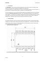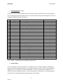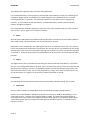
1
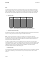
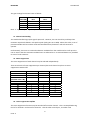
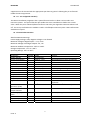
NEDSP900 User Manual Note: Two important things to note about the audio channels, firstly the Gain setting only takes place when the module initialises. This means that any change in audio Gain setting can only be done before powering the module. Secondly, due to the design of the DSP device silicon, at 0dB audio gain selection, there may be up to 9dB of insertion loss between the module input and output. 8. Channel 1 Gain Module Pin 16/ Module Pin 15 Module Pin 5 Gain (dB)
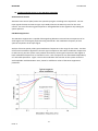
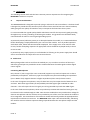
Gain Bit 2 Gain Bit 1 Gain Bit 0 0 1 1 1 12 1 1 0 15 1 0 1 18 1 0 0 21 0 1 1 24 0 1 0 27 0 0 1 30 0 0 0 Note: ‘1’ is pin left open or pulled up to 1.8V, ‘0’ is pin pulled to ground. 9. Automatic Gain Control (AGC) Like the other control pins, pin 26 (Cnl 1 AGC On/Off) requires pulling to ground to invoke the AGC action on. Leaving this pin unconnected or high will inhibit the AGC action. Note: The AGC control pin does not require the module to be re‐powered to take effect. The AGC action makes use of the full 30dB Gain range and as such inhibits any pre‐set gain. When operating it keeps the audio output level within 10dB of the maximum module output level, no matter how much the input level is varying. The AGC has a unique action, in that it recognises speech in a similar way to that of the Noise cancellation programme. If there is no speech present, the AGC tends to hold the audio gain until it next recognises a speech pattern. This holding of the Gain setting means that the audio does not suddenly increase or start to ‘breath’ when the speech disappears. Any small amount of recognisable speech will start the AGC tracking again. 10. Channel 2 Gain This channel has less gain and therefore unsuitable for direct connection to a microphone, however, it does still have sufficient gain to be used with many low level output devices such as receiver detectors. 5 Issue: 3