1
r ,
-
•
nle
Elektronik fUr den Modellbau
Entwicklung, Herstellung, Vertrieb und Support
SonderlOsungen
User Manual for GlowControl 1_2 LiPo
V3
incl. receiver battery monitor and automatic power
control
Thank you for decide on a product from rainbow-tronic We developed an intelligent system which already satisfied lots of model pilots. Smce we are actIve model-builders too we know where it depends on: Safe technology, universal use, low power consumption. ami all this to favourable price. This manual should help you to take pleasure in and profit from our product. Please read the manual carefully before use to find the correct configuration of (~lowControl for your application, GlowControl meets the valid European norms and EMC rules, (E:
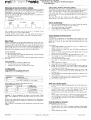
Status-LED
Th muglh d·tI'
I erent fl ash sequences t he status- LED'I II f ormed
! Sequence
• Flash cycle 1,5 s
Flash cycle 0.5 s (2x per
second)
I Constant flash cycle 0,25
s (4x per second)
! Short tlash cycle 0,25 s
Constant
ON
or
~g
Const~nt OFF Double tlash every 2,5 s
I Inverted optical image
DCSCI'iption
receiver voltage on, no glow function Glow function active, throttle position inside glow
:
range
"
Start mode active tor max, I minute
Auto boost active for I s Transmitter is switched OFF or invalid signals
appear. Receiver voltll~e OFF or J I disconnected
No SIgnals from the receiver, transmitter OFF
! receiver hatterv falls below 4,5V/55V for min, 0,5
Is
.
Glow battery empty, voltage below 3, I V
I No glow battery connected or voltage helow 2,7V
Description
Flash cvcle 2,5 s
By the use of GlowControl the current throogh the glow plug is adapted to
the requirement of the combustion of the motor. This CTeatcs a smooth run of
the engine in the lower speed range. especially in idle mode, In addition the
transition from low to high speed is positive mtluenced.
GlowControl 1_2-LiPo is deSIgned lor 1- and 2- cylinder engine
applications. The necessary battery Iype is I LiPo cell O,7V),
In addition GlowControl is monitoring the receiver battery and warns the
pi lot correspondingly,
Warnmg: Ultra-brtght spec wI LED' Do not look (ilreclm/o the llght
Fom short distance. It can harm your eyes I
Functions
I
Connection of GlowControl to 4 or 5 cell receiver batteries possible
without any configuration.
2. The glow battcry should have I cell (3,7 LiPo), The capacity oflhe glow
cell depends on the glow time you would like to have (>= 800 mAh.
ISC).
3. No additional switch necessary in the
circuit
4. At GlowControl the glow range can
freely chosen, It is programmed
once and is always present until it will be re-programmed.
5, The AUTOBOOST functioo rdeases addillonal glow energ) when the
throttle is opened rapidly, This caTCS for a good response ofthe engine.
6. (;lowControl has a STAJn MODE (see later description) which can
help to start the engine or to re-start a "lazy" cylinder.
7. In case of reduced glow battery voltage Glow('ontrol automatically
adapt the power to the glow plugs.
8. Via the ultra- bright Status-LED Glow(:ontrol informs you about the
actual status. A brief descnption you will find below. Please install the
LED in an "easy to see" position inside the cockpit or in the fuselage.
9. For security reasons the POSI\1'."'. function keeps GlowColltrol in stand
by mode after the receiver voltage i, ;;wltched on even if the throttle
stands in idle position, To release the glow function the throttle has to be
moved slightly,
10. GlowColltroi monitors the receiver battery voltage. If the voltage falls
below 4.5V (4 cell battery) or 5,5V (5 cell battery) for more than 0.5 s
the status-LED will invert the optical image and keeps it until reset of
battery voltage. The number of cells will be detected automatically
during programming Gll)w(:ontrol
I I. GlowControl monitors also the glow battery voltage in real time, If the
voltage falls below 3.1 V the slatlls-LED will indicate it. The glow
function will be aborted,
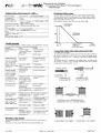
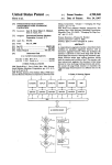
Connection of GlowControl 1 2 LiPo Vol
1 Zelle I cell
vom ~~~~~:rrl---"ll===:::=:=====~. receiver
gelb I yellow
.m.
Iblau /
bl~ I
-
Anschlussschema GlowControl fUr 1 Zylindermotoren
Connection diagram GlowControl for I cylinder motors
1 Zene / cells
n
~~::~iO--------~::::====::::::::::::~~~
~
gelb!
yellow ~
Anschlussschema GlowControl fUr 2 Zylindermotoren
Connection diagram GlowControl for 2 cylinder motors
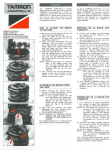
Connect GlowControl to engine and glow battery according to the sketch. The status-LED should be installed in an "easy-to-see" position inside the cockpit or in the fuselage. For damping of vibration GlowColltrol should not covered in foam or similar. Please fix it with Dual Lock tape or similar. The GlowColltrol unit should be installed most far away irom the receiver and the glow plug cahle should run direct to thc motor and should not cross or run paralic I to servo cab!.:s. Nole' In case you connect the battery and/or the glow plug via terminals please check frequently if the screws are tightened. An untightened contact can be responsihle for radio interferences in the Operating and control devices
Aller programming GlowColitrol do not need any further handling. Here are
brief descriptions of the components:
On the board
Item
Function
Programming release
JI
J2
!
J3
J4
TI
~escription
Release lor programming GlowContro1. If the I
jumper is disconnected the programming is I
r~leased, when connected it i, interlocked.
No, of glow reter to topic CONFIGURATIOr-.:
plugs
Glow current r~fer to topic CONFIGliRATION
.. CONFIGURATION
Glow current
Store bullon Stores the values for glow begin and idle
positi(J11
receiver system. •
r
onlc
Elektronik fUr den :vIodclibau
Entwicklung, Herstellung, Vertrieb und Support
SonderlOsungen
Detection of receiver battery voltage
GlowControl is cquippcd with an automatIC detection of the no. of cells of
the receiver batterv pack. The detection in done during the programming of
GlowControl. It has to make sure a 5 cell battery is above 6V during the
programming. Therefore the battery should be fully charged.
The no. of detected cells will be II1dicated during every power-up of
GlowContml by the status LED:
•
I long pulse
• 4 or 5 short pulses (No. of cells)
I long
pulse
4 or 5 pulses
I long pulse ILJL_______r L r L Glow battery monitor and power control
The voltage of the glow battery is monitored in real timc mode In case of
voltage drop the power to the glow plugs will be automatically adapted to
ensure a constant behaviour over the voltage range of the glow battery.
If the voltage drop;; below 3.1 V the glow [unction will be aborted in order to
save the tiPo cells. To cancel the hmitation please move the throttle out of
the glow range.
The status LED will also indicate if no glow battery is connected to
GlowControl. A glow battery with less than 2,7V is not detected.
Safety instructions
•
•
•
•
Note: An empty 5 cell battery could be detected as a 4 cell battery! Please
charge the ballery and re-program GlowControl.
A wrong detected receiver battery does nnt am:cl the function of
GlowControl. Just the receiver battery monitor does not indicate correctly.
Start-Mode
Because of the unique start-mode of GlowControl you can lift up the glow power to the set maximum (depending of Band .14). This can be necessary if your motor will not start in idle position (i.e. needs 1i3 of throHlel In this position the glow power is already slightly lower than the maximum and your motor possibly will not start. If you now activate the start-mode the max. glow power will be present as it normally will be just in idlc position. Activate start-mode You can activate the start-mode: •
Move the throttle slick 3 times fast forwardiretard. The last movement
ha, to end inside the glow range.
Note: The stall-mode can only be active while the throttle stick is inside the
g10\V range~
Cancel start-mode The start-mode can be cancelled in 2 ditferent ways: I. Move the throttle stick out of the glow range
2. Automatic cancellation app. I minute after aclivation.
Configuration
GlowControl has to be configured before use!
ON
Jumper is set, OFF
Jumper is NOT set
-+
-+
GlowControl ean be adapted to the required glow power.
Programming of GlowControl
Preparaliol1s
fo prepare the programming of GlowControl please program first your
transmitter and all relevant servos. especially the range and direction of the
throttle servo. Connect (he glow plug cables to the engine and set the trim
lever to "0".
Programming
I. Connect GlowControl to the receiver by use of a Y - eable or a free
channel of the recciver \\ith mixer.
2. Switch on the receiver Voltage. The status-LED flashes according to the
descrihed sequence.
3. Remove J I. Status-LED stops flashing when throttle stick was moved
after the system was powered 011.
4. Put throttle stick ill position where glowing should start (i.e. 50%)
5. Press button TI at tile GlowControl board. The position is stored,
status-LED flashes I time.
6. Move throttle stick tnto idle position.
7. Press again TI. This position Will be slOred too. Status-LED flashes 2
times.
8. Replace the jumper J I properly.
9. Switch oITthe receiver voltage tor min. 5 seconds.
10. Finish l The programming is now complete and the stored values are
present after each "power on" of the receiver Voltage. Are-programming
is. of canse. possible at any lime.
II. Connect the glow battery with GlowControl. Please take flotice of the
polarity' A wrong connection can destroy (~lowColltrol and is no
guarantee case.
12. Place all components inside the fuselage. Please pay also attention to the
centre of gravity.
13. Please check the range of your radio system (With active glowing) as
you should do it atter installation of any electronic device.
Now G/Oll/Controlls ready to use.
Daily start of the engine
•
•
•
Attention: A wrong configuration can destroy your glow plugs l Please
always start configuration with the lowest glow power set up (Be-J4 NOT
set)!
In order to save energy the glow power can be reduced. This is depending of
the motor and the environment. Please try to find out the best configuration
tor your application.
Note: A change in eonfiguration will be accepted atter re-power the receiver
voltage!
Please note GlowControl heats the glow plug. Turning the propeller
while glowing is active can start the engine Therefore
Do not reach in the range of the propeller.
Keep children away from the engine.
Switdl off the receiver voltage while not using the engine.
•
•
Swilch on receiver voltage. GlowControl do not heat the glow plug at
this tlllle.
As usual draw In the gas. Put the throttle in full speed position. The
status-LED flashes in 1.5 s cycle. Glow function is off Tum the
propeller some revolutions while keeping the carbureltor do,ed.
Move the throttle stick in start position (idle pos. l. Glow function is now
active.
Start the engine in the usual way. Is the throttle stick not in idle position
and the glow power is not sufficient activate the START-MODE.
Now you can start your model On own intcrest you should warm-up the
engine hetorc starL
Stop the engine at ground
Stop the engine in the usual way:
•
Put the throttle in idle p,)sition.
•
Move the trim lever to close the carburettor completely. GlowControl
switches otf the glow power. The engine stops. Status-LED flashes
slow.
•
Switch off the receiver voltage.
r
Elektronik fUr den Modellbau
Entwicklung, Herstellung, Vertrieb uDd Support
SonderlOsungen
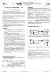
Technical Data GlowControll 2 LiPo V3
Definition of glow range
The glow range is calculated by the micro controller from ditferent values. The basic information are the programmed values. GlowColltrol computes Irom this the glow range. It starts at the programmed value and ends in idle position plus app.50% of trim range, The "auloboost" function can be active also out of glow range. 3.6V to 8V (4 - 5 cells NiCd oder NiMH) 2mA
i
Positive
Universal connector for Futaba/Graupner. MPX
I
(other on request)
lc::onncclion glow battery .. 9pen or 2mm gold plugs Recommend glow plug All known glow plugs can be used type No. of glow plugs I - 2 (other on request) No. of cells of glow I ct'll LiPo 3.7V (4.2V max.) battery Switch-off voltage glow 3,IV battery Min. glow batt voltage 12,7V Receiver voltage
Consumption Receiver impulse
Receiver connection
Trimmbereich
... ~ Trim range
50%
Trouble shooting
~
-"'''
image do not change
while Illoving throtrle
stid;, via full ranGe
Status-LED shows
correct hehaviour, pi
do not glow
Status-LED lights
constantly, Ilickers or
double flash signals
every 2,5 seconds
Throttle position
inside glow range but
no glow power. staluSLED flashes slow
Programmed values
wi \I not be stored
Glow range not
programmed
Charge battery
After power on the
receIver voltag.; the
throttle stick was not
moved slightly (safety
function)
: Jumper J I was not
removed betGH)
Move throttle stick
slightly
(if in supply range included)
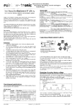
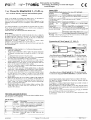
The glow plug cable GPC should be connected to the glow plug as shown in
the sketch. It will be fixed with a locker screw. Because of thermal reasons
please leave a small gap of 0,5 - I mm (app, 0.04") between plug and cable
connector.
The ground cable GC is connected 10 the engine chassis according to the
skctcll below, To ensure a safe electrical connection please use a serrated
washer between engine and cable conn.:clor.
-
~
Set mixer correctly
UcScheibe! Washer
Switch on transmitter
,/
FaCherS~ibe
serrated washer
Anschluss GCI
Connection GC
Engine do not start
even glo\\ battery is
fully charged
Statlls-LED lights up
with short interrupts,
radio system and
Glow(;olltrol works
IStatus-I.ED flashes in
2 second cycle
!
=jjJlIIHIuHuH
Switch off the receiver
: voltage tllr min. 5 s
i If possible move throttle
Ground cable min.
Masseleitull!\ min.
i,5qmm,I
stick closer to idle
l position
engine
: Activate start-mode
Switch off and on again
Receiver voltage was
fallen below 4,5V/5,5V will reset this function,
for more than 0.5 s
recharge hattery_
Glow battery is empty
No glow battery
detected
: Glow batt. connected
I while GlowControl
was powered on. ...
Anschluss GPCI Connection GPC Remove J I before
programming
proQranlming
Receiver voltage was
not interrupted for min.
55
Throttle stick not in idle
position, glow power is
not sufficient to start
Voligas
Full throttle
Connection of glow plug cable and ground cable
Re-program the glow
range (i,e. mid to idle
position)
Glow battery almost
empty
i Mixer for throttle servo
not sct to I 00%,
Transmitter not
switched on
GIOhleistung
(3low power
Programmierter
GIOhbeginn
Progr. glow beginn
Leerlauf
Idle
In general GlowControl IS a reliable system. In case something do not work
like eXI)ected you will find the cause in the following table'
Problem
! Cause
Action
: Receiver voltage
Sialus-LF:O do not
! Switch on voltage I
tlash
switched on! receiver l Charge battcry
battery empty
J I not set
Sel J I proper
i Status-LED Hashes,
> ,
!
"
Anschluss zwei l-Zylindermotoren
Connection of two I-cylinder engines
Charge glow battery
l Connect glow battery
I
Move throttle stick out of •
glow range temporary.
Handling of the Jumper
Please handle the jumper with care, Pull and stick them by use offingers or tweezers. Pick them only at the foreseen nat end, Keep the unused jumper safe. Connection 2-cyl. engine
Connection I-cy1. engine