1
-
"",VB
•
-niC
User Manual for GlowControl 1_2
Elektronik fUr den Modellbau
Entwicklung, Herstellung, Vertrieb und Support
Sonderlosungen
(E:
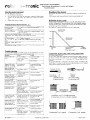
Status-LED
V3
Through different flash se uences the status-LED infonned:
inc!. receiver battery monitor
Thank you for decide on a product from rainbow-tronic. We developed an intelligent system which already satisfied lots of model pilots. Since we are active model-builders too we know where It depends on: Sate technology. universal use. low power consumption. and all this to favourable pnce. This manual should help you to take pleasure in and protit from our product Please read the manual caret\J!ly before Ilse to tind the correct configuration of (;iowControl lor your application. GlowControl meets the valid European norms and [MC rules. ~Sequence
I Flash cvcle 1.5 s
I Flashc~c1e 0.5 s (2x per
, second)
• n':onslant flash cycle 0.25
I s (4x per second)
Short !lash cvcle 025 s
~Constalll . ON
or
I tlickerin"
i Constant OFF
~ flash every 2,5 S
Inverted optical image
By the lise of GlowControl the current through the glow plug is adapted to
the requirement ()f the combustion of the motor. This creates a smooth nm of
the engine in the lower speed range, especially in idle: mode. In addition the
transition from low to high speed is positive int1uenced.
GlowConlrol 1~2 IS deSigned for I and 2- cylinder engilW applications. The
necessary battery type is I cell (1.2V) NiMH or NiCd rurr.$low plug.
In addnion GlowControl is monilOl'ing the receiver baUery and warns the
pilot correspondingly.
!
Auto boost active for I s
Transmitter is switched OFF or invalid signals,
a ear.
I
. Receiver voltage OFF or J I disconnected
I No signals 1'1'0111 the receiver, ~an~n~ittcr OFF
receIVer battery lalls below 4.' VJ~.) V for mill. 0.5 i
·s
I
Description
Description
receiver v(>ltage 011, no glow function
i Glow flUlCliol111ctive. throttle position inside glow'
ranoe
: Sta~t mode active t'Or max. I minute
Glow battery em t
No glow battery connected or voltage below
I 0.8Viccll
i
rFiash cycle 2,5 s
1_
I
... Warning: Ultra-bright special LED! Do not look direct into the light
)rom short distance. It can harm your eyes'
Connection of GlowControl 1 2
v~
Functions
I. Connection of GlowControl to 4 or 5 cell receiver batteries possible
without any contiguration
2. The glow bat,,;ry should have I cell (1,2V) per glow plug. The capacity
of the glow cell depends on the glow time you would ,like to have (>=
2000 mAh).
3. No additional switch necessary in the glow circuit
4. At GlowColitrolthc glow range can be freely chosen. It is programmed
once and IS always present until It will be re-programmed.
5. The 6UTOBQOST function releases additional glow energy when the
thr(lule is opened rapidl}. This cares lin 11 good response of the engine.
This function can be disabled via conllguration bridge.
6. GlowControl has a STAIn MOPI (see later description) which can
help to start the engine or to re-start a "Iazy" C) Iinder
7. In case of reduced glow ballery voltage GlowColltrol automatically
adapt the power to the glow plugs.
8. Via the ultra- bright Status-LED GlowControl int'Orms you about the
actual status. A brief deSCription you \\ ill find helow. Please install the
LED in an "ea:iY to sec" position inside the cockpit or in the fuselage.
9. For security reasons the POSM!ji) function keeps GlowControl in stand
by mode after the receiver voltage is switched 011 even if the throttle
stands III idle position. To release the glow function the throttle has to be
moved slightly.
10. GlowControl monitors the receiver battery Voltage. If the voltage falls
below 4.5V (4 cell battery) or 5,5V (5 cell battery) for more than 0,) S
the statlls-LED will invert the optical image and keeps it until reset of
battery voltage. The number of cells will be detecled automatically
during programming (;lowConlrol
11. GlowColltrol monitors also the glow battery voltage in real time. If the
voltagl: falls belo\v I,OV the status-LED will indicate it The glow
function will be aborted.
vom E.t:ing=rr~____l:==~==~====~
frolT!
receIver
Status
-LT.TJ~ - - - -......
Anschlussschema GlowControl fUr 1 Zylindennotoren
Connection diagram GlowControl for 1 cylinder motors
2 Zellen I
gelb I
yellow
please ciJeckji-equently if/he screws (Ire lightened. An untightened contact can be responsible for radIO interferences in the receiver system. Flln,~c:::.tI~o:.::n~-L.1:;:Desrriptioll
, Program
, Release
I ming release I jumper
I()r programming GlowControl If the
is disconnected the programming is
released. when connected It I, interlo",ckc:,:e:.:de,.'_-I
f-cc
toPJCC()NF'iGl:'RAllON
J2,------+-i':--B~oo-s-te-r--+-lre-cf:-er-I-()......
J3
J4
I Glow current Jrcfer to topic CON FIGURA TI(..::.)N~_ _ __ I Glow current·
refer to topic C'ONIIGURAni)N
1'1
, Store bullon i Stores thc-valucsro;:- glo~ begin and idle
1'--_ _ _ _
iPosition
..._ _ _._ _ _.
-LI_____
I:
Connect GlowControl to engine and glow ballery according to the sketch.
The ,tallis-LEI) shnuld be mstallcd ill an "easy-to-see" position inside the
cockpit or inlhe fu,elage.
For damping of VIbration GlowControl should not covered in roam or
similar. Please iiI. II with Dual Lock lape or similar
The Glow('ontrol unit should he Installed most far away from the receiver
and the glow plug cable should run direct to the motor and should not cross or
run parallel to servo cables
NOle. In case you connect the battery and/or the glow plug via terminals 011 tile board
i
....iii
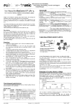
Anschlussschema GlowControl fUr 2 Zylindermotoren
Connection diagram GlowControl for 2 cylinder motors
After programming GlowControl do not need any further handling. Here are
brief descriptions of the components:
/Jj
cells'~
+
Operating and control devices
rit~m
1 Zelle i cell i l
,
I
•
ro··nlc
~ Elektronik fUr den Modellbau
Entwicklung, Herstellung, Vertrieb und Support
Sonderlosungen
Glow battery monitor
Detection of receiver battery voltage
GlowContnl1 is equipped with an automatic detection of the no. of cells of
the receiver battery pack. The detection in done during the programming of
GlowControl. It has to make sure a 5 cell battery is above 6V during the
programming. Theretore the battery should be fully charged.
The no. of detected cells will be indicated during every power-up of
GlowContl'ol by the status LED:
•
I long pulse
•
4 or 5 short pulses (No. of cells)
r···········I... I~~.!::II~e
4 or 5 pulses
pulse
I long
pulse
s-LJ1________ ~
..........................................................
The voltage of the glow battery is monitored in real time mode.
Wht:n (;lolI'Control is powered on. the connected glow cells are detected
automatically and the switch-off voltages are calculated. Is no glow cell
connected when the system is switched on, I cell is selected I
In case "10\\ hatt" is detected the glow function is aborted. This state can be
released by leaving the glow range with the throttle stick. The cut-off occurs
• at IV/cell.
If no glo\\ battery is connected the Status-LED indicates this. A glow battery
with less than 0,8V will be not detected!
Note The recognition or the number of cells has just intluence to the cut-off
levels. In case the detected failed (no glow hattery connected when system
was switched on and later a 2 cell hattery was connected) the general
functionality of Glow('olltl'ol is ensured. Only the cut-otT' function is not
given.
............................................................................ Note: An empty 5 cell battery could be detected as a 4 cell battery.' Please
charge the battery and re-program GlowControl.
Safety instructions
A wrong detected receiver battery does not affect the function of
GlowContl'ol. Just the receiver battery monitor does not indicate correctly
•
•
•
Please note GlowColltrol heats the glow plug. Turning the propeller
while glowing is active can start the engine. Theretore
Do not reach in the range or the propeller.
Keep children away trom the engine.
Switch otlthe receiver voltage while not using the engine.
Start-Mode
Because of the unique start-mode of GlowContl"ol you can lift up the glow
power to the set maximum (depending 01'.13 and .14) This can be necessary if
your motor will not start in idle position (i.e. needs 1/3 of throttle). In this
position the glow power is already slightlv lower than the maximum and vour
motor possibly will not start. If you no\\ activate the stat't-mode the max.
glow power will be present as it normally will be just in idle position.
Activate start-mode
You can activate the start-mode:
•
Move the throttle stick 3 times fast forward/retard. The last movement
has to end inside the glow range.
Note: The start-mode can only be active while the throttle stick is inside the
glow range!
Programming of GlowControl
Preparations
To prepare the programming of GlowControl please program tirst your
transmitter and all relevant servos. especially the range and direction of the
throttle servo. Connect the glow plug cables to the engine and set the trim
lever to "0".
Programming
I. 2. 3. Cancel start-mode The start-mode can be cancelled in 2 ditferent ways: I. Move the throttle stick out of the glow range
2. Automatic cancellation app. I minute aHer activation.
4. 5. 6. 7. Configuration
GlowControl has to be configured befOl'c use!
ON
Jumper is set, OFI
Jumper is NOT set.
-+
-+
8. 9. 10. The jumper .12 sets the boost function!
Jumller.J2
Configuration
OFF
Booster enabled
ON
Booster disabled
11. GlowControl can be adapted to the required glow power.
.J3 and .14 determine the glow power
Jumper.J3
.JllmperJ4
Configuration
OFF
OFF
SO % glow power
OFF
ON
90 % glow power
OFF
ON
95% glow power
ON
ON
100% glo\\ powcr
c
Attention: A wrong configuration can destroy your glow plugs! Please
always start contiguration II ith tht: lowest glow power set up (.13+.14 NOT
set)!
In order to save energy the glow power can be reduced. This is depending of
the motor and the environment Please try to tind out the best configuration
tor your application.
Note: A change in contiguration will be accepted after re-power the receiver
voltage!
12. 13. Now GlowControl IS ready to lise.
Daily start of the engine
•
•
•
•
•
04.10.2009
Connect GlowControl to the receiver by use of a Y - cable or a free
channel of the receiver with mixer.
Switch on the receiver voltage. The status-LED tlashes according to the
described sequence.
Remove.ll Status-LED stops tlashing when throttle stick was moved
after the system was powered on.
Put throttle stick in position where glowing should start (i.e. 50%)
Press button TI at the Glow('ontrol board. The position is stored,
status-LED tlashes I time.
Move throttle stick into idle position.
Press again T I This position will be stored too. Status-LED tlashes 2
times.
Replace the .i'umper .II properly.
Switch off the receiver voltage tor min. 5 seconds.
Finish' The programming is now complete and the stored values are
present after each "power on" of the receiver voltage. Are-programming
is, of cause, possible at any time.
Connect the glow battery with GlowControl. Please take notice of the
polarityl A wrong connection can destroy GlowColltrol and is no
guarantee case.
Place all components inside the fuselage. Please pay also attention to the
centrc of gravity .
Please check the range or your radio system (with active glowing) as
you should do it after installation of any electronic device.
Version: Vl 2 LiPo-0-G8 Switch on receiver voltage. GlmvControl do not heat the glow plug at
this time.
As usual draw in the gas. Put the throttle in full speed position. The
status-LED flashes in 1,5 s cycle. Glow function is off. Turn the
propeller somc revolutions while keeping the carourettor closed.
Move the throttle stick in start position (idle pos.). Glow function is now
active.
Start the engine in the LlsLlal way. Is the throttle stick not in idle position
and the glow power is not sunicient activate the START-MOnE.
Now you can start your model. On own interest you should warm-up the
engine bct<Jre start.
Seite 2 von 4
., -
ral
-.~--.---
•
nle
... ------~~-----~
Elektronik fUr den Modellbau
Entwicklung, Herstellung, Vertrieb und Support
SonderlOsungen
... - - - - - - - - - - - - - - - - - - - - - - - - - - -
Stop tbe engine at gronnd
Handling of tbe Jumper
Stop the engine in the llsllal wa}
•
Put the throttle III idle position.
•
Move the trim lever to close the carhurettor completely. GlowControl
switches oil Ihe glow power. The engine stops, Status-LED llashcs
slow,
•
Switch ott'the receiver voltage,
Please handle the jumper with care, Pull and stick them by use oftingers or
tweezers
Pick them only at the foreseen flat end. Keep the unused jumper safe,
Tecbnical Data GlowControl 1 2
:U}V to 8V (4
Definition of glow range
The glow range is calculated by the micro controller nom different values, The basic intormation are the programmed values, GlowControl computes from this the glow range It starts at the programmed value and ends in idle position plus app.50% of trim range. The "autoboost" function can be active also out of glow range, V3
5 cells NiCd oder NiMH)
Trimmbereich
I
UnivCTsal connector for FutabalGraupner, MPX
~~__~__~~____-+~(o~t~heronreq.u~e~S~I~)~~___________________,
i COllnection glow batte
0 en or 2mm ooldrlugs ----:------------1
: Rccommerldglow plug All known glow plugs can be used
t, e
i No, ofglow plllgs
1 I - 2 (other on request) ~)f cells of glow i I cell 0.2\') :\i~1II or NiCd per glow plug : batte~'rLY~~~____~-+~~______________________________~
glow: I,OV
/'Triin range-
_.(3-'(jhlei~u.nJl.
50%
/' , 9'ow power
O,8V
, Min, glow batl. voltage
Programmierter
Gli.ihbeginn
Progr. glow beginn
Leerlauf
Idle
Vollgas
Full throttle
Trouble sbooting
In general (;lowControl is a reliable system, In case something do not work
like ex ccted vou will find the cause in the fOllowing::,:ta:;;:b..:.;le:,:.:____________
'
lL
Connection of glow plug cable and ground cable
~~~~~~----4i~(~:a~I=ls~C----~------_c~A~c~tl~·o~n~--~------~
Status-LED do not
Receiver voltage
I" Switch on voltage /
tlash
,witched otT/ receiver
Charge baltery
,~3Iterv empty
____--+_______________-=--=
J I not scI.
Set J I proper
, Status-LED Ilashes,
imagc do not change
~
I
Glow range not
I programmed
Re-program the glow
range (i,e. mid to idle
position)
...while moving thm.ttle
i
stick VIa full range
I
Charge battery
Status-LED shov.s
i Glow battery almost
i correct behaviour, plug, empty
[Mixer lor thwttlc servo Set mixer correctly
, do Illlt glow
I not set to 100%.
Switch on transmitter
Status-LEO lights
I' Transmitter not
constantly, tlickers or
switched on
: double nash SIgnals
i every 2,5 seconds
rThrottle position
After power on the
Move throttle stick
inside glow range but
receiver voltage the
slightly
no glow poweL slatus throttle stick was nOl LED !lashes slow
: moved shghtly !safety : hlllction)
Programmed values
Jumper J I was not
I Remove J I before
will not be stored
removed before
, programming
'if in supply range included)
The glow plug cable (;P(: should be connected to the glow plug as shown in
the sketch. It will be fixed with a locker screw. Because of thermal reasons
please leave a small gap or 0.5 I I11Ill lapp. (l.04") between plug and cable
connector.
The ground cable GC is connected to the engine chassis according to the
sketch below. To ensure a safe electrical connection please lise a serrated
washer between engine and cable connector,
U-S.ch.ci.btiWasher
/
I
Facherscheibe serrated washer Anschluss GPCI
Connection GPC
Anschluss GCI
Connection GC
I
~amming
Receiver voltage was
I Switch off the receiver
not interrupted tor min, : voltage jbr min. 5 s
5s
I
-
Anschluss zwei I-Zylindermotoren
Connection of two I-cylinder engines
~}'.'.il~I.].
'. 'I~f
i!§i
-I
i Status-LED flashes in
: No glow battery
i Connect glow battery
: detected
Glow batl. connected
Move throttle stick out of i
while GlowControl
glow range temporary.
___________-=--'.,\""a=sLPowered 011.'--_ _" -_____________- - '
2 second cycle
1
~.
=1 1Ii5
. . . . [I
==
Connection 2-cyL engine
Connection l-cyL engine