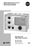
1
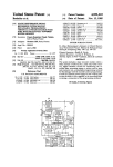
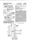
United States Patent [19]
Patent Number:
Date of Patent:
[11]
[45]
Johnson et 21.
[54] AUTOMATICALLY ADJUSTABLE DELAY
4,490,055
Dec. 25, 1984
Printer", Balcezak et al., vol. 21, N0. 12, May 1979, pp.
FUNCTION FOR TIMED TYPAMATIC
4759-4760.
IBM Technical Disclosure Bulletin, “Multiple Repeat
[75] Inventors: Carl F. Johnson; James M. Williams,
[21] Appl. No.: 393,928
Rates for a Terminal Keyboard”, Leimer, v01. 23, No. 2,
Jul. 1980, p. 770.
IBM Technical Disclosure Bulletin, “I/O Keyboard
Switching of Keys from a Typamatic to a Non-Typa
matic Status", Motola, vol. 24, No. 11B, Apr. 1982, p.
[22] Filed:
MCS-48 Microcomputer User’s Manual, published
both of Lexington, Ky.
[73] Assignee:
International Business Machines
Corporation, Armonk, NY.
5859.
Jun. 30, 1982
[51]
Int. Cl.3 .............................................. .. B41J 5/28
[52]
US. Cl. .................................... .. 400/51; 400/704;
1978 by Intel Corporation, pp. 1—l—2-15.
Primary Examiner-Ernest T. Wright, Jr.
340/365 E
[58]
Field of Search ................... .. 400/50, 51, 52, 321,
[56]
400/368, 369, 704, 70; 340/365 E, 365 S
References Cited
Attorney, Agent, or Firm—Laurence R. Letson
[57]
board utilizing a timed delay to determine whether a
U.S. PATENT DOCUMENTS
depressed key is indicative of the desire to print or
2,717,688
9/1955
Brooks .............................. ,. 400/704
$270,438
9/1966
Ephraim
3,436,735
4/1969 Hoiseth
3,618,034 11/1971
3,643,773
.....
. . . ,.
display repetitive letters represented by that key. The
typewriter is provided with a technique for automati
cally adjusting the length of the delay such that a slow
400/704 X
400/368 X
Hecker ...... ..
2/1972 Holmes, Jr.
3,781,874 12/1973 Jennings
400/51 X
typist with sluggish ?nger movement will automatically
400/50 X
cause the extension of the delay time and thereby pre
vent unwanted repetitive characters while a fast, very
rhythmic typist will not cause the automatic extension
of the delay time and thereby will bene?t from a shorter
delay time and will have a higher output or productiv
400/51 X
3,973,662
8/1976
Fulton .......... ..
4,106,011
4,189,246
8/1978
2/1980
Melanson et a1. ............ .. 340/365 E
Kane et a1. ..................... .. 400/51 X
4,263,582
4/1981
Dumbovic ..
4,323,888
4/1982
Cole .............................. .. 400/368 X
.. 400/50 X
.... .. 340/365 5
ity as a result thereof.
The automatic extension is accomplished by timing the
period of time that keylevers are held depressed and
FOREIGN PATENT DOCUMENTS
1411549 10/1975
ABSTRACT
A typewriter is described which has an electronic key
when that time approaches but does not exceed the
preset automatic delay time, the delay time is then ex
United Kingdom ................ ., 400/51
OTHER PUBLICATIONS
IBM Technical Disclosure Bulletin, “Variable Time
tended a predetermined amount.
Delay for Hammer Firing in Rotating Disk-Type
11 Claims, 3 Drawing Figures
NC
SE'J‘JENTIAL llliEili'OGAllOk
0‘ EACH IEY PQSIIION
Vii
1
\
IVPAMAYIB 11H?
‘
1
(Mill ELAPSEZ
‘
an
.
DELAY
NEEUED
1
1,
moors 5 KEY TRANSITION
OUTPUT 10
RITER ,1 TERMINAL
PROCESSOR
" ‘22
US. Patent
Dec. 25, 1984
Sheet 1 of 3
TYPEWRITER/PRINTER +___ KEYBOARD
PROCESSOR
—>
PROCESSOR
4,490,055
US. Patent
Dec. 25, 1984
Sheet 2 0f 3
4,490,055
FIG. 2
I00
INITTALIZATION
RoIITIME
-/
T
I02
OTHER KEYBOARD ROUTINE
/
u ‘
———_.0
<
TYPAMATIc
ROUT'NE
TYPAMATIc FLAG SET ?(FO) YES
404
-/ I34
NO
SEQUENTIAL INTERROGATION
OF EACH KEY POSITION
,Ios
430
CURRENT TYPAMATIC
KEY RELEASED?
DEPRESSED /
RELEASED?
,
“0
CHECK TIMER FLAG;FI /
IF TIMER IS RUNNING-
“6
AYES
REsET TYPAMATIC
FLAG(FO)
I24
432/
STOP T'MER - 426
sToP TIMER
v
sTART TIMER
H8/
CHECK TIMER FLAG; Fl
IF TIMER IS RUNNING
_ sToP TIMER
/
I20
CHECK ELAPSED
428
-
/
DELAY TIME;
CHANGE DELAY
VALUE IT NEEDED
PRocEss KEY TRANSITION
OUTPUT TO
TYPEWRITER / TERMINAL
PROCESSOR
-/
I22
US. Patent Dec. 25, 1984
Sheet30f3
4,490,055
FIG. 3
TIMER
INTERRUPT
202
ADD 0?- JUMP TO COUNT
/
___________________________ _ TOLWTFR
ROUTINE
DECREMENT TIMER OVERFLOW COUNTER.
CHECK FOR ZERO.
204
_
/
T
IS OVERFLOW COUNTER ZERO?
LOAD ZEROS
/
208
INTO TIMER
/
STORE CURRENT ADDRESS
T
SET TYPAMATIC FLAG FO
,i
)246
STOP COUNTER. RESET
TIMER FLAG. Fl
T l
RETURN
210
1
4,490,055
2
Inasmuch as the operator or typist is unique in their
timing, rhythm, speed and the length of time that a key
AUTOMATICALLY ADJUSTABLE DELAY
FUNCTION FOR TIMED TYPAMATIC
BACKGROUND OF THE INVENTION
is held depressed, it is not possible to provide a single
timed delay which is acceptable or optimal for a great
5
With the advent of electronic keyboards on terminals
and typewriters, there has been a need for improving
OBJECTS OF THE INVENTION
It is an object of this invention to adjust the delay and
to lengthen the delay between the time a typamatic key
is sensed as being depressed and the time that repetitive
cycles are initiated under machine control.
It is another object of this invention to reduce errone
the operation of those keyboards to accomplish repeat
characters. On mechanical keyboards which have the
typamatic or repeat character capability, by holding the
keybutton depressed to a second force level, the ma
chine will repeatedly cycle and print repetitively the
character indicated by the keybutton.
ous typewriter inputs by sensing the typamatic keys and
sensing the speed by which the keys are released and
However, with keyboards using electrical or elec
based thereon, adjusting the delay period.
tronic contacts or a change in capacitance to indicate
It is still another object of the invention to increase
the depression of a keybutton for character selection, it
is preferable to utilize an alternate technique of selecting
repeated characters from the second depression force
level approach.
With electronic keyboards, whether they be capaci
typing accuracy on timed typamatic keyboards for
slower typists by providing a longer period within
which they may react to release a keybutton.
20
tance or switch arrangements, all the positions on the
keyboard are scanned or sequentially queried to deter
cessor which controls the scanning and other organiza
tional functions of the keyboard, will detect the held
down condition and repeat the character automatically.
This approach, although having many advantages, re
quires a timed delay after the depression of the keybut
ton before a second and subsequent cycles are initiated
to insure that the typist has had an opportunity to re
move the ?nger from the button and thereby not inad
vertently initiate detection of the made or depressed
SUMMARY OF THE INVENTION
Electronic typewriters typically have keyboards
which may be electronic in nature. If an electronic
mine whether a keybutton has been depressed to select
the character. One technique for repeating a character
is the depression and release and redepression of the
desired key. This approach will produce a plurality of
identically repeated characters.
For keyboards having the repeat character character
istic, the keybutton may be held depressed and the pro
majority of the operators.
keyboard is implemented on a typewriter or, for that
matter, an electronic data processing terminal, the key
board is controlled by a processor which accepts signals
from the keyboard responsive to a scan routine. The
scanning of the keyboard is a technique for sequentially
addressing each of keybutton positions and determining
30
whether a circuit is complete through that keybutton
position to indicate the operator having depressed the
keybutton. In addition to the scanning or sequential
interrogation of each key position to determine a
change in the state of the switching device utilized, the
keyboard processor is capable of performing timing
functions. The keyboard processor can time the period
condition indicating repetitive characters. This may be
accomplished by requiring a timed delay of 500 or 600
milliseconds from the time that the ?rst keybutton clos
that a particular selected keybutton or a group of key
buttons are held depressed.
For example, a single keybutton such as the space bar
may be timed for each depression of the space bar or the
keybuttons which are designated as typamatic or repeat
character keys may be timed whenever any one of them
ing is sensed. If, after the predetermined delay time, the
is held depressed. If a typamatic key is held depressed
key is determined to be still held in a depressed condi
for a period which is within 100 milliseconds of the
tion, the processor assumes that repetitive characters 45 preselected delay time, the keyboard processor auto
are to be printed and initiates the appropriate printing
matically resets the delay time value to a next higher
cycles to form those characters on the record media,
delay time unless the delay time is already at the maxi
typically at machine cycle speed and continuing until
mum preselected value.
such time as the keybutton is released and the keyboard
If the keybutton is still depressed and the switching
processor detects the change of condition from a de 50 element in the keyboard indicates that the circuit is
pressed key to a released key.
made for that particular keybutton at the end of the
Typewriters and data processing terminals utilizing
electronic keyboards and which are presently in the
market utilize a ?xed time delay, typically 600 millisec
onds. This 600 millisecond delay is too long a period for
a fast typist since a fast typist can typically key charac
ters at an average rate of one character every 200 milli‘
timed delay period and that keybutton represents a
typamatic character, the keyboard processor detects
this condition and begins to repetitively output the
character signal to the main typewriter or printer pro
cessor to cause the printing of that character at the
printer machine rate.
seconds or less. The net result of the 600 millisecond
Further, the adjustment of the delay time is supressed
delay period is that a fast typist has their typing rhythm
interrupted by virtue of having to stop and wait an
inasmuch as it is clear at the end of the delay period that
60 the reason for continued depression of the key was to
additional 300-400 milliseconds for the repeat mode to
cause typamatic printing.
begin to be initiated.
Release of the typamatic key prior to the end of the
A shorter time delay is undesirable from the stand
delay period will prevent any repeating characters.
point that a slow or sluggish typist will allow the ?ngers
Additionally, the depression of any other key on the
to rest on the keyboard keys and may inadvertently 65 keyboard will be detected notwithstanding the contin
leave the key depressed for such a period of time as is
ued depression of the typamatic key, and the depression
necessary to initiate the repetitive printing or typamatic
of this other key during the time delay period will indi
printing of a character.
cate a desire to subsequently print a second character
3
4,490,055
4
and not enter the repeat mode and therefore will defeat
of the depression of a selected typamatic key to initiate
the entry into the repeat mode notwithstanding the
subsequent printing cycles.
continued depression of the typamatic key.
Printing cycle is used in the conventional term associ
ated with typewriters, but it should be recognized that
‘
If the typamatic mode of operation is entered after
the time delay period, there will be no change in the
the displaying of a character on a display by means of
delay time inasmuch as the long period of depression of
illumination and electronic character generation may .
a typamatic key is due to the desire for repetitive typing
also be included within the terminology of printing.
Referring to FIG. 1, the typewriter 10 has a keyboard
12 associated therewith. In addition, typewriter 10 also
rather than due to sluggish typist action or slow re
moval of the ?nger from a typamatic key.
has a printing assembly 14 capable of physically mark-i
DRAWING
ing a record sheet 15 to display characters by any con
ventional typing or printing technology and the specif- ,
FIG. 1 illustrates a generalized system wherein a
keyboard processor controls and receives signals from 1
the keyboard and provides those signals to a main pro
cessor which, in turn, provides signals to the keyboard
processor, to the printer and receives feedback signals
from the printer.
FIG. 2 is a How diagram illustrating the flow of oper
ations for carrying out the automated adjustment of the
delay time for a timed typamatic keyboard.
FIG. 3 is a flow diagram illustrating the flow within
the timer interrupt routine.
ics of that portion of the device do not constitute part of ‘ '
the invention described herein. Keyboard‘processor 16 i‘
5
is the Intel 8048 microprocessor described above and is
electronically connected to and interfaced with data
lines leading to and from keyboard 12. The techniques
of attaching these data lines to the keyboard processor
16 and the particular arrangementof keyboard 12 are
20 conventional and do not constitute any portion’ of the
invention.
'
Keyboard processor 16 is electronically interfaced ,
with the typewriter/printer processor 18 hereinafter
DESCRIPTION OF THE INVENTION
referred to as the printer processor 18. The printer
For purposes of implementation and for purposes of 25 processor 18 performs all the necessarycontrol func- '_
describing this invention, a microprocessor sold under
the designation Intel 8048 microprocessor sold by the
Intel Corporation of Santa Clara, Calif., is used as the
control of the electronic keyboard 12. Hereafter, the
Intel 8048 microprocessor will be referredras the key 30
board processor 16.
The Intel 8048 microprocessor is readily commer
tions and determinations for operating the printing as» .
sembly 14 of the typewriter 10 to cause the printing of , ‘
characters. Printer processor 18 sends control signals to t
the printing assembly 14 and receives vthe necessary
feedback signals from the printing assembly 14 to main- '
tain control of the printing ‘assembly ‘14 in an appropri4
ate sequence. Printer processor 18 receives character‘
cially available and the Intel Corporation provides man
uals on its use indicating available register designations,
available ?ags and their designations, and a list of in
signals and other necessary control signals from the
keyboard processor 16 and provides feedback to key-l 7
board processor 16. The keyboard processor 16 likewise
struction codes which may be utilized to cause the pro
has two-way connections to the keyboard 12 to provide 1
cessor to function.
signals to the keyboard 12 for purposes of scanning the
Additionally, the Intel 8048 has an eight bit timer
keyboard 12 and a return path for signals from the key-'
which counts in response to clock pulses generated by
button switching elements 11 in keyboard 12 such that
the timing clock of the microprocessor 16 and will run 40 the signals generated thereby may be transmittedtto the
through a complete 256 count timing sequence and
keyboard processor 16.
overflow every 20.48 milliseconds (Msec).
Referring to FIG. 2, the initialization routine in‘ block ~ "
The Intel 8048 processor, in addition to being readily
100 accomplishes the loading of preset information into;
available in the marketplace, is a conventional piece of
designated registers R0. R3-R7 within the processor 16
electronic equipment widely used in many applications. 45 when the processor 16 and typewriter 10 are initially
The architecture and operation of the Intel 8048 pro
turned on. This information is permanently stored "in ;
cessor is described in the MCS-48 Microcomputer
non-volatile read only memory locations within the ‘
User’s Manual, Copyright 1978, Intel Corporation,
keyboard processor 16 and is not changeable type of
pages l-l through 2-16, which are incorporated herein
by reference.
information.
50
The Intel 8048 processor includes within its structure
at least a clock, timer/event counter, registers, memory
I
‘
The information loaded into the respective registers ‘
with their initial values are set forth below by wayof
illustration and not by way of limitation.
locations, read-only-memory and flags F0 and F1.
‘
These elements of the Intel 8048 processor are utilized
to control the monitoring and altering of the timed
delay of the typamatic function as it is more completely
described below.
Appendix A attached is a listing of instructions, state
ments and instruction codes and addresses which will
control the keyboard processor 16 to perform the rou 60
tines described in the flow diagram of FIG. 2.
Description of or
Information Contained
Register Designation
RO
in the Register
Pointer to cause the
addressing of selected
registers R20—R29
R2
Timer over?ow count '
While this system is described in connection with a
R3
R4
Fractional delay value
Whole portion current
typewriter 10, and utilizes the input from the typewriter
R5
Fractional portion current
delay value
keyboard 12, it should be recognized that this same
typamatic adjustment of the delay may be implemented
delay value
R7
Status Register
on any system which utilizes an electronic keyboard
R20
9
and which has typamatic keys and where the processor
responds to a timed delay period after the ?rst detection
R23
90
65
'
'
»
‘
‘
.
j
'
4,490,055
5
-continued
Description of or
Information Contained
Register Designation
in the Register
R24
R25
R26
R27
R28
R29
6
After the initialization routine is accomplished (block
100), other keyboard routines not germaine to this in
vention are performed by the keyboard microprocessor
16 (block 102) and, by way of illustration, include the
checking of the code key 13 on a typewriter keyboard
12 to determine whether it has been depressed signaling
19
120
24
151
29
180
a command other than a character selection when com
bined with a character key depression. Additionally. a
check of the printer feedback signal from the printer
processor 18 may be made at this time to maintain the
keyboard processor 16 in synchronization with the
printer processor 18 and the printer assembly 14.
With the initializing of the registers R0-R29 as indi
cated herein, the timing delays are stored such that they
are accessible by the processor 16 not in terms of actual
time delay but, rather, in terms of complete timer cycles
which require 20.48 Msec per timer cycle. The tabula
tion below indicates a time period delay and the number
pa 5
The flow then proceeds to block 104 wherein a deci
sion is made as to whether the typamatic ?ag F0 is set.
Initially, the typamatic flag F0 has been initialized in the
initialization routine in block 100 in an unset condition
and, therefore, the flow proceeds through the “No"
of whole timer cycles and a value which, when loaded
path to the sequential interrogation of key position sub
into the timer, will result in a fractional timer cycle very
routine in block 106. In electronic keyboards, the key
closely approximating the desired time and which cor 20 board processor 16 sequentially addresses the matrix of
relate to the initialization values of registers R20-R29
keyboard switching elements 11 to determine which, if
above.
any, have been caused to create a transition from a make
to a break or from a break to a make condition. As a
200
300
400
500
600
Msec
Msec
Msec
Msec
Msec
Whole Cycles
Fractional Cycle
9
14
19
24
29
ll 61
90
120
151
180
result of this sequential interrogation, the ?ow proceeds
to block 108 wherein a decision is made as to whether a
key transition from a break to a make or make to a break
has occurred in the keyboard 12. If no transition has
occurred, then the flow returns by the path indicated
and reenters the decision block 104 to determine
whether the typamatic flag has been set. This loop con
The timer is a 256 cycle or an eight bit timer which
operates on the 80 microsecond clock pulse period thus
resulting in a complete timer cycle from O to 256 in
20.48 milliseconds. Thus, to get a 200 millisecond delay
will require a total of nine complete timer cycles and
0.76 fractional timer cycle. In order to operate the timer
within its operational constraints, an initial fractional
value is loaded into the timer from which the timer will
then count upward to its capacity of 256. Thus, a value
loaded into the timer cycle is the portion of the timer
cycle not required and, thus, represents a starting point
for the timer to count upwardly from. To determine the
fractional amount to be loaded into the timer, the equa
tinues until such time as a key transition has been de
tected and such a decision has been made that a transi
tion occurred in decision block 108.
Upon the detecting of a key transition, the flow pro
ceeds from block 108 to block 110 wherein the typa
matic question is posed “Has the typamatic flag been
set?” If the typamatic flag F0 has not been set, the pro
cessor flow proceeds through the no path to decision
block 112 which determines whether the key transition
determined in block 108 was a depression or a release. If
the transition was a depression of the key, then the path
goes to the decision block 114 where the determination
is made as to whether the key which ransitioned was a
tion [20.48—0.76(20.48)]/0.08=61 is illustrative of how 45 typamatic key such as a period 19 or space 21 key and
the fractional value for a 200 millisecond time delay is
if the key was a typamatic key 19, 21 then the flow path
determined. The 20.48 is representative of the time
goes by the yes route to check the timer ?ag F1 and if
required for a complete timer cycle and 0.76 represents
the timer is running, to stop the timer ‘as indicated in
the fractional portion of a timer cycle required in addi
subroutine block 116. This condition is a condition
tion to the complete timer cycle for the desired time 50 which may exist if the typamatic key 19, 21 just de
delay.
pressed was the second consecutive typamatic key 19,
Similar calculations may be performed to arrive at
the whole or fractional number values for the registers
R20 and R29 for each of the predetermined time delays.
For each of the predetermined time delays, two regis 55
ters have been dedicated to storing the numbers and,
thus, they are available to the processor 16 to update the
time delay when appropriate.
Again, referring to FIG. 2, after the initialization
procedure and the initializing of the typamatic flag F0
21.
-
Upon the completion of stopping the timer, it will
have the effect of initializing the timer and the timer is
then restarted in block 118. By stopping the timer and
restarting the timer, this insures that the time delay
period being considered is applicable only to the most
recent typamatic key 19, 21 and effectively removes the
possibility of inadvertently typing repeat characters
and timer flag F 1 to an unset condition, the sequence of
from a former typamatic key 19, 21 when it is clear by
the depression of a subsequent key that the operator
events portrayed by the flow diagram may proceed. It
should be noted that flag F0 and F1 are arbitrary ?ags
earlier key depression.
does not desire to enter the typamatic mode on the
which may be used and their use is available to the
Returning to decision block 114, if the determination
designer for any purpose desired and may be set and 65 is that the key transition was a depression and that it was
reset as desired under instruction control. These flags
not a typamatic key 19, 21, then if the timer flag F1 is set
F0, F1 are provided in the Intel 8048 used as the key
and thus the timer is running, the timer is stopped as
board processor 16.
indicated in block 120. This insures that any previous
7
4,490,05 5
typamatic key 19, 21 which remains depressed does not
trigger subsequent repeat characters.
Upon the completion of either the restarting of the
timer in block 118 or the stopping of the timer in block
120, the key transition is processed and an output is
generated to the typewriter printer processor 18 to
accomplish printing of the selected character in accor
dance with the other keyboard routines and the flow
returns from the key transition processing block 122
8
typamatic key address, then ‘the flow follows the YES
path to block 132.
routine
Referring
is illustrated.
to FIG. For
3, the
best
?ow
understanding,
ofthe. timer the
interrupt
timer , ‘ I
portion of the processor l6continues to operate simul
taneous with other functions of the processor 16 per-,
forming the flow illustrated in FIG. 2. Every time the
timer of the processor 16 reaches a condition where all"
bits are
, that is indicated as an overflow condition
10 and a timer interrupt signal emits from that portion of '
back to enter block 104 for the next cycle.
the processor 16 to interrupt the sequence of operations
Referring back now to decision block 112 where the
in the flow of FIG. 2. As dictated by the construction of a
determination was made asto whether a key transition
the Intel 8048 processor, utilized as the keyboard pro
with no typamatic ?ag F0 set was a depression or a
cessor 16, any time there is a timer overflow condition I
release and where the decision was that the transition
was a release, the determination is then made as to
whether the key 17, 19, 21 released was a typamatic key
in decision block 124. The purpose of this is to accom
modate the stopping of the timer upon the release of the
key (Block 126).
If the key 17, 19, 21 was a typamatic key, then the
stop timer routine (block 126) is the next function of the
processor 16 and the time elapsed determined in block
128. If the time elapsed is within approximately 100
milliseconds of the current delay time, then the subrou
initiating a timer interrupt command, the processor 16
immediately goes to address 07 whichis a jump to count
routine instruction. This is‘ illustrated at block202'.
From the jump to count instruction stored in address 07
(block 202), the count routine is entered to effect the
counting in register R2 for keeping track of thettime
delay. Upon the receipt of a timer interrupt command
and the processing of the jump to count instruction ,
(block 202), the timer over?ow count (register R2) is ‘
decremented by one and a check to see if the timer
25 over?ow count is now zero (block 204).
tine represented by block 128 will change the delay
If the over?ow counter contents is not zero, then the
value to the next larger predetermined delay value as
represented in registers R22-R29. The check of the time
is effectively accomplished by checking the value in
flow follows the NO path from block ‘206 where that‘
decision is made to block 208 where a routine directs
that zeros are loaded into the timer. As soon as the zeros . ‘ '
register R2 and comparing it with a preset numerical 30 are loaded into the timer as commanded by subroutine I
value of 5. If it is equal to or less than 5, the typamatic
indicated at block 208, the timer will immediately begin .
19, 21 key has been held down to within approximately
counting in response to the timing pulses ‘of the key
100 milliseconds of the current delay time and the sub
board processor clock.
’
routine will make the desired change in the delay time
Thereupon, the flow goes to return block 210. Upon.
value.
35 entering the return routine (block 210), the processor 16
After the completion of making such a change, the
returns to the flow in FIG. 2 at precisely the point it was
key transition is processed and in this case would not
when the interrupt command was issued by. the timer.
initiate a character. The key transition processing is
The flow of FIG. 2 then continues uninterrupted .until ;
accomplished in block 122.
such time as a subsequent timer interrupt. command
Referring back to the decision in block 124 as to
whether the released key 17, 19, 21 was a typamatic key
and with a "NO” response to that determination, then
the next step is the processing of key transition 122.
Returning to decision block 110 wherein a determina
tion is made upon a key transition as to whether the
typamatic flag F0 has been set and where the flag F0
has been set, the decisional ?ow will be to decision
block 130 where a determination is made as to whether
the current typamatic key 19, 21 has been released. In
the event that the current typamatic key 19, 21 has not
been released, the flow returns to reenter block 104. In
the event that the current typamatic key 19, 21 has been
issues upon a timer overflow condition.
Referring back to block 206, if the over?ow counter
contains a zero after the decrementing in block 204, the
YES path is followed and the current address of thekey
position which has been held depressed throughout'the
entire period of time that the timer was overflowing a
suf?cient number of times todecrement the timer over~
flow counter to zero, is stored (block 212). This address
will be utilized by the main flow in FIG. 2, speci?cally
block 130, during a check routine to determine subse
quently when that typamatic key 19, 21 is released.
After the storage of the typamatic ‘key address (block , ~
212), the typamatic ?ag F0 is then set (block 214) and
released (block 130), then the typamatic flag F0 is reset
the counter is stopped. This effectively prevents'the. ‘
by the subroutine represented by block 132 and then the
timer from continuing to time‘ inasmuch as there is no
key transition is processed by block 122.
55 need to do so until either the typamatic key 19, 21‘ has. I
In decision block 130, there is a check procedure
been released or another typamatic key 19, 21 has been
performed to determine whether the current typamatic
depressed. This operation is represented by block.216.'
key 19, 21 has been released. This check compares the
At the same time, the timer flag F1 is reset to a zero I
last key transition address or the key location designa
condition indicating that the timer is not functioning. At * .
tion on the keyboard 12 which last indicated a key
transition with the current typamatic key address to
determine if the current typamatic key 19, 21 was the
one released. If the transition indicated as a release is
this point, the flow goes to return (block 210) wherein '
the main flow of FIG. 2 is reentered at‘the ‘precise point
that the timer interrupt occurred‘and the process illus
trated by the flow diagram in FIG. 2 continues uninter- ‘
not the current typamatic key 19, 21, then there is con
rupted until interrupted by another interrupt command. . i‘
tinued scanning of the keyboard 12 by reentering at a 65
The rectangular blocks in the above routine represent
point upstream from block 104. When the current typa
subroutines which are performed under a series of t in
matic key is released (Block 130) and there is a compare
structions contained in theread-only-storage portion of
between the last key transition address and the current
processor 16. The sequential interrogation of each key
4,490,055
position in block 106, the other keyboard routines in
block 102 and the processing of the key transition 122
10
APPENDIX A-continued
have not been listed in Appendix A inasmuch as they
are conventional routines which can be found in elec
tronic keyboards presently on the market, for example,
in the IBM 6240 keyboad manufactured and sold by the
International Business Machines Corporation, Armonk,
NY. The routines enumerated in Appendix A involve
LO'
CATION
PRO
GRAM
CODE
7
04
LA
BEL
NMEMONICS
COMMENTS
Jmp Count
Timer
Interrupt
Pointer
some aspect or signi?cantly add to the understanding of
1O
the invention herein and, therefore, are included.
Appendix A has a code listing of instructions set forth
8
9
A
B
C
using conventional notation and is grasped into five
D
9A
[Following is part of an initialization routine]
E
F
columns, Location, Program Code, Label, Nmemonics
and Comments.
The routine in block 134 is the routine which controls
the output of characters in the repeat mode. It checks
the printer feedback signals to determine when the
printer is ready for the next character.
10
05
ENI
Enable Timer
ll
85
CLR F0
Reset
Interrupt
Typamatic
Flag
12
The sequential interrogation (block 106) is a routine
which is dictated by the type of keyboard used, such as
A5
CLR F 1
conductive, capacitive or membrane.
In conjunction with the interrogation controls, a
register is used to store indicators of status in bits 0, 1
13
B8
14
Z0
l5
14
Mov R0, H20
Initialize
Pointer
Call load
Places
delay
current delay
value in
R4 and R5
and 2 and are designated:
Bit 0—-typamatic bit, l-typamatic, 0 not typamatic
Bit 1—key transition bit, l-transition, 0 no transition
Bit 2—-key depressed/released, l-depressed, 0 released
The interrogation routine determines (I) if the key
position is typamatic and sets bit 0, (2) if the key 17, 19,
25
16
keyboard 12.
Speci?c examples of these routines will not aid in
60
19
[Other keyboard routines located here]
1A
21 is up or down, (3) if key transition has occurred and
sets bit 1, and (4) if the key 17, 19, 21 has been released
or depressed (bit 2). The processing of the key transition
(block 122) controls output of data to the printer/type
writer processor 18 and controls the scanning of the
ID
7.
B6
Pl
JFOP0
By adjusting the time delay through which an opera
tor must hold a typamatic key 19, 21 depressed in order
to get repetitive character printing, the slow typist will
Flag is Set
21
24
22
04
23
26
24
14
25
—
Jmp P2
P0
Call Typamatic
P2
Call Interrogate
26
14
27
—
automatically with a minimum of errors, cause the ad
28
FF
Mov A, R7
justment of the time delay typically within three or four
typamatic key cycles, to a value which will insure that
the typamatic characters are only printed when desired
29
32
J81, P3
key transition
28
04
Jmp, Pl
beginning
2C
20
2D
12
2E
31
2F
04
30
3l
36
14
A typist with a fast and very rhythmic stroke will not
32
-
adjust the time delay as rapidly and therefore will be
able to avail the typist of a shorter delay time for any
33
95
intentional typamatic characters.
34
04
35
52
36
52
37
4O
38
12
typically typamatic keys with a relatively high degree
P3
IEO, P4
mode
keybutton will, of necessity, condition the typewriter 10
within a very, very few keystrokes on either of these
keys 19, 21 to extend the delay time.
Jmp, P5
P4
Call check
CPL F0
0
l
2
3
4
5
6
Reset
typamatic
?ag
Jmp, P6
APPENDIXA
NMEMONICS
Jump if in
typamatic
of usage. Thus, a slow typist who tends to linger on the
LA
BEL
No transition,
go to
the typewriter 10 is turned on and typing commences
inasmuch as the spacebar 21 and period key 19 are both
PRO
GRAM
CODE
Get Index
or Register
Check for
45
keystroke. This adjustment will occur very rapidly after
LOCATlON
Jump if
Typamatic
35
understanding the invention and are not part thereof.
and which will also accommodate a slow or sluggish
Reset Timer
Flag
Jump to
Process key
transition
P5
JB2, P7
Jump if key
depressed
COMMENTS
65
39
3C
3A
04
3B
52
J90, P8
Jump if key
is typamatic
Jmp, P6
Jump to
Process key
Transition
4,490,055
111
112
APPENDIX A-continued r
LO-
PRO-
CA-
GRAM
LA~
TION
CODE
BEL
NMEMONICS
P8
Call stop timer
3C
3D
3E
14
89
04
Jmp, P6
' APPENDIX A-continued
LO-
PRO
CA‘
GRAM
LA~
TION
CODE
BEL
NMEMONICS
COMMENTS 1
79
7A
FC
sum
Mov A, R4‘
a
Move whole
Jump iftimer
713
AA
Mov R2’ A
"“m‘mg
7c
FD
Mov A, R5
7D
AB
Mov R3, A‘
7E
62
Mov T, A
Load fractional
Start T ‘
5211:: into
sum timer‘
COMMENTS
5
Jump to
73
74
75
Process key
76 1
Transition
3F
52
40
12
Jmp, P9
41
4A
42
04
JFl, P10
43
46
I
44
a4
Jmp, P6
I
Timer
t
Transitions
52
g;
48
04
value to ‘R2
' v
Move fractional '
i
Jump to
15
“W955. key
45
is
value t0lR3
a
‘
t
t
PM
can mp “me”
Jmp, P6
‘
73 ‘
Jump‘if key
*5 typamatlc
‘
'
77
10
P7
‘
Jump to
7F ‘
55
82
,
20
FI
Process key
,
,
S64 “mar ‘?ag ’
Transitions
49
4A
52
04
43
4E
4c
04
4D
50
Jmp, P11
33
84
Jump if timer ‘
running
85
25
Jmp, P12
86
‘
87
88 ‘
4E
14
4]:
39
50
51
14
7A
P12
Call Start timer
52
14
P6
Call Process
remaining
Key Transition
time less
53
—
54
04
55
20
p11
can Stop timer ‘
30
89
65
Stop
Stop tent ‘
Stop timer
8A ‘
B5‘
timer
Cpl Fl
88
FA
Reset timer, 7
?ag
‘
Check if ~
Mov A, R2
Jmp, Pl
Jump to
beginning
BC‘
8D
‘
56
35
37
03
8E
05
8F‘
F6
Cpl A
Add A, H05
k
‘
JC, increase
57
delay
58
timeless than ' v
100 msec
5A
90
5B
91 1
5C
40
6A‘
A
s3
[)3 ‘
5E
94
5F
‘
F0
Load
Mov A@R0
Delay
95
Gets delay
values using
pointer and
96 ‘
,
97 ‘
45
98
puts them in
99
R4 and R5.
62
7
RET»
92
5D
61
Jump'iF carry Y
' set (remaining ‘
59
60
I
than 100 msec
AC
,
Mov R4.A
9A
18
1NCRO
9B
63
F0
Mov A@R0
9c
64
AD
Mov RS’A
65
33
EA
1
2325 1R2’
A5
‘
If
I
Ret
50
eserved or,
9D
66
code to store
9E
I
‘
current key,
(,7
68
9F
69
A0
95
Cpl F0
Sets typamatic‘
Al
A2
65
B5
Stop tent
Cpl Fl
Stop timer
Reset timeri
6A
address.
FC
In-
Mov A, R4
Crease
dry’
If stop
timer routine
indicates that a
?ag
55
new delay value
'
is needed, this
A3
routine will
A4
A7
‘
A5
27
Count
increment Ra
pointer‘and call
load delay.
A6
62
A7
93
XRLA, H29
6D
C6
.12, Delay 1
6E
72
6F
18
INC R0
14
Call'load delay‘
AB
RET
AC
AD
72
A8
1
Delay
65
A9‘ ‘
AA
?ag
~
‘
Imp’ Count 3
~
1
D3
29
60
83
m4
60 ‘
6B
6C
70
71
‘
‘
Clr A
t
MOV T, A
Count
2‘
Load zeros
11110 lime!‘
RETR‘
4,490,055
13
APPENDIX A-continued
1.0CA-
PR0
GRAM
TION
CODE
LA
BEL
14
insufficiently long to cause said repetitive charac
ter display or function operation.
4. The method of claim 3 wherein said adjusting com
NMEMONICS
prises:
COMMENTS
providing a plurality of selected time periods and
selecting the next larger of said time periods and
substituting said next larger of said time periods for
said ?rst predetermined time period.
5. A character displaying apparatus having a key
AF
We claim:
1. A method of controlling the sensing time period for
detecting a condition indicative of a desire for a charac
board capable of at least some repetitive character and
function selection through key depression for a pro
ter to be repetitively displayed comprising:
providing a preset sensing time period, the exceeding
of which by the depression of a single character
key is indicative of a repetitive display operation;
measuring the period of time that a selected control
longed period of time comprising:
means for detecting key depression and release,
means for timing the period between key depression
and key release,
means for comparing said period with said prolonged
key is depressed;
period,
comparing said period of time with a predetermined
standard time period;
means for initiating repetitive character or function
increasing said sensing time period when said period
of time exceeds said standard time period, whereby
an operator who is slow and holds keys depressed
for a longer period of time than normal will not
20
period is within a predetermined amount of time of
undesirably display multiple characters.
said prolonged period, thereby automatically sens
ing a sluggish typist and increasing the prolonged
2. The method of claim 1 wherein increasing said
sensing time period comprises selecting one of a plural
selection when said period exceeds said prolonged
period, and
means for increasing said prolonged period when said
25
ity of varying sized sensing time periods.
period a key must be held depressed to cause repet
pressed to initiate repetitive character display or func
itive character or function selection.
6. The apparatus of claim 5 wherein said means for
increasing comprises a timer over?ow counter and
means for selecting predetermined values for use in said
tion operation comprising:
timer over?ow counter.
3. The method of controllably changing the time
period a key of a keyboard must be maintained de
providing a keyboard capable of electronically sens
7. The apparatus of claim 5 wherein said means for
ing key depression;
timing comprises a timer counter of ?xed capacity
which overflows when counted to capacity, and said
providing a ?rst predetermined time period;
means for comparing comprises a timer over?ow
determining the period of time a key on said keyboard
35 counter for accounting for timer over?ow events.
is depressed;
8. The apparatus of claim 5 wherein said means for
determining if said period of time is less than but
timing is operatively associated with selected keys on
within a predetermined amount of said predeter
said keyboard.
mined time period, and if within said predeter
9. The apparatus of claim 8 wherein said selected keys
mined amount;
comprise a space key and a period key.
adjusting said predetermined time period to a longer
10. The apparatus of claim 5 wherein said apparatus
predetermined time period, thereby lengthening
having said keyboard is a typewriter.
the time period a key must be held depressed to
11. The apparatus of claim 5 wherein said repetitive
initiate repetitive character display or function
character selection comprises repetitive printing of said
operation when a key is held depressed, a period
approaching said predetermined time period but 45 character.
it
50
55
65
it
i
it
i