1
OS-9® for SuperH EBX7709
Board Guide
Version 4.7
w w w. r a d i s y s . c o m
Revision A • July 2006
Copyright and publication information
Reproduction notice
This manual reflects version 4.7 of Microware OS-9.
Reproduction of this document, in part or whole, by any means,
electrical, mechanical, magnetic, optical, chemical, manual, or
otherwise is prohibited, without written permission from RadiSys
Microware Communications Software Division, Inc.
The software described in this document is intended to
be used on a single computer system. RadiSys
Corporation expressly prohibits any reproduction of the
software on tape, disk, or any other medium except for
backup purposes. Distribution of this software, in part
or whole, to any other party or on any other system
may constitute copyright infringements and
misappropriation of trade secrets and confidential
processes which are the property of RadiSys
Corporation and/or other parties. Unauthorized
distribution of software may cause damages far in
excess of the value of the copies involved.
Disclaimer
The information contained herein is believed to be accurate as of
the date of publication. However, RadiSys Corporation will not be
liable for any damages including indirect or consequential, from
use of the OS-9 operating system, Microware-provided software,
or reliance on the accuracy of this documentation. The
information contained herein is subject to change without notice.
July 2006
Copyright ©2006 by RadiSys Corporation
All rights reserved.
EPC and RadiSys are registered trademarks of RadiSys Corporation. ASM, Brahma, DAI, DAQ, MultiPro, SAIB, Spirit, and ValuePro are
trademarks of RadiSys Corporation.
DAVID, MAUI, OS-9, OS-9000, and SoftStax are registered trademarks of RadiSys Corporation. FasTrak, Hawk, and UpLink are
trademarks of RadiSys Corporation.
†
All other trademarks, registered trademarks, service marks, and trade names are the property of their respective owners.
Contents
Installing and Configuring OS-9® 5
Development Environment Overview................................................................................................................................................................
Requirements and Compatibility.........................................................................................................................................................................
Host Hardware Requirements (PC Compatible)....................................................................................................................................
Host Software Requirements (PC Compatible)......................................................................................................................................
Target Hardware Requirements .................................................................................................................................................................
Java Target Hardware Requirements...............................................................................................................................................
Target Hardware Setup..........................................................................................................................................................................................
Settings ............................................................................................................................................................................................................
Jumpers .................................................................................................................................................................................................
Switches .................................................................................................................................................................................................
Connecting the Target to the Host......................................................................................................................................................................
Establishing a Serial Connection................................................................................................................................................................
Building the ROM Image.......................................................................................................................................................................................
Starting the Configuration Wizard .............................................................................................................................................................
Configuring the Coreboot Image...............................................................................................................................................................
Configuring the Bootfile Image..................................................................................................................................................................
Bootfile System Options.....................................................................................................................................................................
Bootfile System Network Configuration .........................................................................................................................................
Bootfile System Disk Configuration .................................................................................................................................................
Building the ROM Image .............................................................................................................................................................................
Creating a Startup File............................................................................................................................................................................................
Example Startup File .....................................................................................................................................................................................
Optional Procedures ..............................................................................................................................................................................................
Loading the ROM Image into Flash Memory..........................................................................................................................................
Embedding the ROM Image in a Bootfile......................................................................................................................................
Setting Up Hawk’s Serial Console ....................................................................................................................................................
Programming the ROM Image into FLASH Memory ..................................................................................................................
Loading the Coreboot Image into Flash Memory..................................................................................................................................
Embedding the Coreboot Image into a Bootfile ..........................................................................................................................
Programming the Coreboot Image into Flash Memory .............................................................................................................
6
6
6
7
7
7
7
7
7
7
8
8
8
8
10
11
11
12
12
12
13
14
14
14
15
15
16
17
17
18
Board Specific Reference 21
Boot Menu Options................................................................................................................................................................................................
PC/104 and Super I/O Interrupts ........................................................................................................................................................................
The Fastboot Enhancement..................................................................................................................................................................................
Overview .........................................................................................................................................................................................................
Implementation Overview...........................................................................................................................................................................
B_QUICKVAL........................................................................................................................................................................................
B_OKRAM.............................................................................................................................................................................................
B_OKROM ............................................................................................................................................................................................
B_1STINIT .............................................................................................................................................................................................
B_NOIRQMASK ...................................................................................................................................................................................
22
22
23
23
24
24
24
24
24
24
3
OS-9® for SuperH EBX7709 Board Guide
B_NOPARITY ........................................................................................................................................................................................
Implementation Details................................................................................................................................................................................
Compile-time configuration ..............................................................................................................................................................
Runtime Configuration .......................................................................................................................................................................
Enabling PCMCIA IDE Interrupts .........................................................................................................................................................................
Before You Start.............................................................................................................................................................................................
Enabling PCMCIA IDE Interrupts on the SuperH....................................................................................................................................
Updating the llcis module..................................................................................................................................................................
Updating the PCMCIA utility .............................................................................................................................................................
Updating the RBF/PCF PCMCIA IDE device descriptors .............................................................................................................
25
25
25
25
26
26
27
27
27
27
Board Specific Modules 29
Low-Level System Modules ..................................................................................................................................................................................
High-Level System Modules.................................................................................................................................................................................
PCMCIA Support for IDE Type Devices ....................................................................................................................................................
Module...................................................................................................................................................................................................
Descriptors ............................................................................................................................................................................................
Real Time Clock............................................................................................................................................................................................
Module...................................................................................................................................................................................................
Ticker (System Clock) Support...................................................................................................................................................................
Module...................................................................................................................................................................................................
Serial Support.................................................................................................................................................................................................
Module...................................................................................................................................................................................................
Descriptors /t3.....................................................................................................................................................................................
Baud Rates ............................................................................................................................................................................................
Module...................................................................................................................................................................................................
Descriptors /term /t1 ..........................................................................................................................................................................
Descriptors /t2......................................................................................................................................................................................
Baud Rates ............................................................................................................................................................................................
Module...................................................................................................................................................................................................
Descriptors /t4......................................................................................................................................................................................
Baud Rates ............................................................................................................................................................................................
Power Management Support .....................................................................................................................................................................
Module...................................................................................................................................................................................................
Parallel Port Support.....................................................................................................................................................................................
Module...................................................................................................................................................................................................
Descriptors ............................................................................................................................................................................................
Keyboard Support .........................................................................................................................................................................................
Module...................................................................................................................................................................................................
Descriptors ............................................................................................................................................................................................
Mouse Support ..............................................................................................................................................................................................
Module...................................................................................................................................................................................................
Descriptors ............................................................................................................................................................................................
Common System Modules List............................................................................................................................................................................
4
30
30
30
30
30
31
31
31
31
31
31
31
32
32
32
32
33
33
33
34
34
34
34
34
34
34
34
34
34
34
35
35
Installing and Configuring OS-9®
This chapter details the procedures for creating an OS-9® bootfile for the SuperH
evaluation board. The following sections are included:
Development Environment Overview
Requirements and Compatibility
Target Hardware Setup
Connecting the Target to the Host
Building the ROM Image
Creating a Startup File
Optional Procedures
1
1
5
OS-9® for SuperH EBX7709 Board Guide
Development Environment Overview
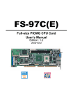
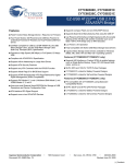
Figure 1-1 shows a typical development environment for the SuperH board. The
component include the minimum required to enable OS-9 to run on the SuperH EBX
board.
Figure 1-1. EBX Development Environment
1
1
Requirements and Compatibility
Host Hardware Requirements (PC Compatible)
Your host PC should have the following hardware:
6
•
a minimum of 32MB of free disk space (an additional 235MB of free disk space is
required to run Java for OS-9)
•
an Ethernet network card
•
a PCMCIA card reader/writer
•
the recommended amount of RAM for the host operating system
•
EPROMs for initial boot image
Chapter 1: Installing and Configuring OS-9®
Host Software Requirements (PC Compatible)
Your host PC should have the following software:
•
Windows 95, 98, ME, 2000, or NT
•
Microware OS-9 for SH-3
Target Hardware Requirements
Your SuperH evaluation board requires the following hardware:
•
3COM Etherlink III required (Ethernet PCMCIA card)
•
an RS-232 null modem serial cable
•
RS-232 terminal software (such as HyperTerminal)
•
PCMCIA ATA FlashDisk
Java Target Hardware Requirements
Your SuperH evaluation board must have the following to run PersonalJava™ Solution
for OS-9:
16MB of RAM
•
4MB of FLASH (Boot)
•
VGA display and PS/2 mouse
•
keyboard (optional)
1
•
Target Hardware Setup
Settings
The factory default jumper settings may not work with Microware OS-9 for SuperH. Be
sure the jumpers and switches agree with the following settings:
Jumpers
Most of the jumpers on the EBX7709 reference board are either connectors or should
be left on their factory defaults. Therefore, they will not be listed in this section. The
following jumpers should be set to the appropriate setting to insure that OS-9 will work
on your reference board.
JP15 (set to closed)
This jumper sets the endian mode for the board.
With the jumper open, the board is set to littleendian mode. With the jumper closed, the board is
set to big-endian mode.
Switches
There is only one eight switch dip switch on the EBX7709 reference board. Refer the
Hitachi EBX7709 User Manual for more information on the switches.
7
1
OS-9® for SuperH EBX7709 Board Guide
Connecting the Target to the Host
Please refer to the Hitachi documentation for information on hardware preparation and
installation, operating instructions, and functional descriptions prior to installing OS-9 on your
SuperH evaluation board.
The factory default settings for the DIP switches and jumpers may not work with OS-9. Be sure
the DIP switches and jumpers agree with the settings in the Settings section.
Establishing a Serial Connection
To connect the SuperH evaluation board to your host PC, complete the following steps:
1. Connect a serial cable to the serial port (SIO5) on the EBX7709 board.
2. Connect the other end of the serial cable to one of the COM ports on the host PC.
Depending on your PC system, you may need either a straight or a reversed serial
cable to make this connection.
If you do not know what type of serial cable your machine uses, try a reversed cable first. If the
connection fails (no boot messages appear in the communication program’s window), then
try a straight serial cable.
1
1
Building the ROM Image
The directions in this section will enable you to create a coreboot image and a bootfile
image that can support user state debugging.
Starting the Configuration Wizard
The OS-9 coreboot image allows for booting from PCMCIA IDE cards. To boot from a
PCMCIA IDE card, you need to place an OS-9 bootfile image on the card. The
Configuration Wizard, a utility included with this package, is used to create this bootfile
image.
To prepare the Wizard, complete the following steps:
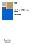
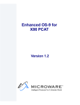
1. From the Windows desktop, select Start -> RadiSys -> Microware OS-9
for <product> -> Configuration Wizard. You should see the following
opening screen:
8
Chapter 1: Installing and Configuring OS-9®
1
Figure 1-2. Configuration Wizard Opening Screen
2. Select your target board from the Select a board pull-down menu.
3. Select the Create new configuration radio button from the Select a
configuration menu and type in the name you want to give your ROM image in the
supplied text box. This names your new configuration, which can later be accessed
by selecting the Use existing configuration pull down menu.
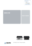
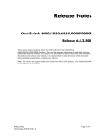
4. Select the Advanced Mode radio button from the Choose Wizard Mode field and
click OK. The Wizard’s main window is displayed. This is the dialog from which you
will proceed to build your image. An example is shown in Figure 1-3.
9
1
OS-9® for SuperH EBX7709 Board Guide
Figure 1-3. Configuration Wizard Main Window
1
1
Configuring the Coreboot Image
This section explains how to configure the coreboot portion of the ROM image that will
support user state programming. To configure the coreboot image, complete the
following steps:
1. While in Advanced Mode in the Configuration Wizard, click the Main
Configuration button. The EBX7709: <configuration name> window appears.
Click on the Debugger tab and click on the Ethernet option button in the
Remote Debug Connection group box. The debugger in the Select Debugger group
box changes to Remote when either the Ethernet or Slip option button is selected.
2. Click on the Ethernet tab and enter the address information in the address text
boxes. For most situations you will need to fill out the following text boxes:
•
IP Address
•
Subnet Mask
•
IP Gateway
•
MAC Address (optional)
If you are unsure of the values for these text boxes, contact your system
administrator.
3. On the Define ROM Ports tab, verify that the console port is 7709 p1 and that the
communication port is 7709 p2. Both ports should be set to 9600.
4. On the Define Other Boot Options tab, make sure only the following check boxes
are selected:
10
Chapter 1: Installing and Configuring OS-9®
•
Override Booter
•
Add to Boot Menu (In the ‘bo’ Boot embedded OS-9000 in place group box)
•
Auto boot (in the ‘bo’ Boot embedded OS-9000 in place group box)
•
Add to Boot Menu (in the ‘lr’ Copy embedded OS-9000 to RAM and Boot
group box)
•
Break - Enter System Debugger
•
Quit - Restart System
5. Click OK to close the window.
6. Click the Disk Configuration button found in the Coreboot Configuration
Buttons group.
7. Make sure the Add to Menu check box in the PCMCIA IDE group box is selected.
8. Click OK to close the window.
Configuring the Bootfile Image
1
After configuring a coreboot image, you need to configure a bootfile image. This section
focuses on configuring the bootfile part of the ROM image.
The SanDisk 4MB and 20MB PCMCIA ATA IDE cards do not work correctly with PCMCIA IDE
interrupts enabled. To make sure that all cards (including the SanDisk cards) work with OS-9,
the default mode for accessing the PCMCIA IDE cards is set to polled mode. If you need to
enable PCMCIA IDE interrupts, see Enabling PCMCIA IDE Interrupts in Chapter 2.
The instructions in this section cover only those Configuration Wizard options that need to be
changed to enable application development with Microware Hawk™. If a default option is
suitable for use with Microware Hawk, then that option is not mentioned.
Bootfile System Options
To configure the bootfile system options, complete the following steps:
1. While in Advanced Mode of the Configuration Wizard, click on the Configure
System Options button.
2. Verify that the 7709p1 option button is selected as the console port and the bps
rate is 9600.
3. Click on the Bootfile Options tab and select the following check boxes:
•
sc16550
•
Parallel port
4. Click on the MAUI® Options tab and select the MAUI® demos you want to run. If
you do not want to run the demos, leave the check boxes deselected.
5. Click OK to save your changes and return to the Configuration Wizard window.
11
1
OS-9® for SuperH EBX7709 Board Guide
Bootfile System Network Configuration
To configure the network, complete the following steps:
1. Select the System Network Configuration button.
2. Ensure Ethernet Connection is checked.
3. Expand the Ethernet Connection tree by clicking on the “+” to the left of it, then
select the Ethernet controller and Ethernet card.
4. Select the Server assigned IP address box or the Specify an IP address; if you select
the ladder you will need to fill in the IP Address and Subnet Mask text boxes.
If you do not know the IP address of your machine, contact your system administrator.
5. Select the Commit Change button.
6. Click on the SoftStax® Setup tab, and select the Enable SoftStax option
button.
7. Click OK to close the dialog box.
1
1
Bootfile System Disk Configuration
To configure the disk, complete the following steps:
1. While in Advanced Mode of the Configuration Wizard, click on the System Disk
Configuration button that is found in the Bootfile Configuration button group.
This enables the PCMCIA IDE function.
2. Click on the RAM Disk tab.
3. Select the Enable RAM disk and the Map RAM disk as /dd check boxes.
4. Select the size of the RAM disk in the drop-down list box immediately below the
Map RAM disk as /dd check box.
5. Click on the IDE Configuration tab and select Enable IDE Disk.
6. Click on the Init Options tab and make sure the /dd option button in the
Initial Device Name group box is selected.
7. Click OK to close the dialog box.
Building the ROM Image
Now that you have configured the coreboot and bootfile images, it is time to build the
ROM image. To do this, complete the following steps:
1. While in Expert Mode of the Configuration Wizard, click the Build Image button
to display the Master Builder window.
2. Click on the Coreboot + Bootfile option button in the Build Type/Options
group box. The Coreboot + Bootfile option button is used to build ROM images.
12
Chapter 1: Installing and Configuring OS-9®
3. Select the following check boxes. The last three items are needed only if you
included MAUI demos in the boot.
•
User State Debugging
•
Disk Support
•
Disk Utilities (fdisk, format)
•
SoftStax® (SPF) Support
•
MAUI Support (optional)
•
Keyboard Support (optional)
•
Mouse Support (optional)
4. Click Build. The ROM image is built and saved in the following directory:
MWOS\OS9000\SH3\PORTS\EBX7709\BOOTS\INSTALL\PORTBOOT.
You should make sure the combined ROM image fits into the flash memory built into the EBX
Reference Platform.
Creating a Startup File
1
5. Click Finish to close the Master Builder window.
When the Configuration Wizard is set to use a hard drive, or another fixed drive such as
a PC Flash Card, as the default device, it automatically sets up the init module to call
the startup file in the SYS directory in the target (For example:
/h0/SYS/startup, /mhc1/SYS/startup). However, this directory and file will
not exist until you create it. To create the startup file, complete the following steps:
1. Create a SYS directory on the target machine where the startup file will reside
(for example: makdir /h0/SYS, makdir /dd/SYS).
2. On the host machine, navigate to the following directory:
MWOS/OS9000/SRC/SYS
In this directory, you will see several files. The files related to this section are listed
below:
•
motd: Message of the day file
•
password: User/password file
•
termcap: Terminal description file
•
startup: Startup file
3. Transfer all files to the newly created SYS directory on the target machine. (You can
use Kermit, or FTP in ASCII mode to transfer these files.)
4. Since the files are still in DOS format, you will be required to convert them into the
OS-9 format with the cudo utility. The following command is an example:
cudo -cdo password
13
1
OS-9® for SuperH EBX7709 Board Guide
This will convert the password file from DOS to OS-9 format.
For a complete description of all the cudo command options, refer to the Utilities Reference
Manual, included with this CD.
5. Since the command lines in the startup file are system-dependent, it may be
necessary to modify this file to fit your system configuration. It is recommended
that you modify the file before transferring it to the target machine.
Example Startup File
Below is the example startup file as it appears in the MWOS/OS9000/SRC/SYS
directory:
-tnxnp
tmode -w=1 nopause
*
* OS-9 - Version 3.0
*Copyright 2001 by Microware Systems Corporation
*The commands in this file are highly system dependent and
*should be modified by the user.
*
*setime </term
;* start system clock
setime -s
;* start system clock
link mshell csl
;* make "mshell" and "csl" stay
in memory
* iniz r0 h0 d0 t1 p1 term ;* initialize devices
* load utils
;* make some utilities stay in
memory
* tsmon /term /t1 &
;* start other terminals
list sys/motd
setenv TERM vt100
tmode -w=1 pause
mshell<>>>/term -l&.
1
1
Refer to the Making a Startup File section in Chapter 9 of the Using OS-9 manual for more
information on startup files.
Optional Procedures
The following procedures may be performed once you have installed and configured
OS-9.
Loading the ROM Image into Flash Memory
You should reprogram the flash memory sparingly because the flash memory can be
reprogrammed only a finite amount of times.
14
Chapter 1: Installing and Configuring OS-9®
Embedding the ROM Image in a Bootfile
To embed the ROM image in a bootfile, complete the following steps:
1. In the SuperH Configuration Wizard window, click the Configure System
Options button. The SH3:<your configuration name> window appears.
2. Click on the Bootfile Options tab.
3. Click PF-ROM. PF-ROM will include the ROM image in the new bootfile as a data
module.
4. Click OK to close the window.
5. Click Build Image to open the Master Builder window.
6. Click Bootfile Only Image and then click Build. The bootfile containing the
ROM image is built and saved in the following directory.
MWOS\0S9000\SH3\PORTS\EBX7709\BOOTS\INSTALL\PORTBOOT
The Save As button is enabled when the build is completed.
7. Save the bootfile to the root directory of the PCMCIA IDE card. Use the name
os9kboot.
1
8. Click Finish to close the Master Builder screen, and select File -> Save
Settings to save the configuration.
9. Select File -> Exit to quit from the wizard.
Setting Up Hawk’s Serial Console
Once the bootfile is created you will need to connect to the EBX7709 Reference
Platform. To set up Hawk’s Serial output window as a serial console, complete the
following steps:
1. From the Windows desktop, select Start -> RadiSys -> Microware OS-9
for <product> -> Microware Hawk IDE.
2. Once the Hawk IDE has started, open the Serial window by selecting Customize
-> Toolbars. The Toolbar Customization dialog box appears.
3. Select Serial in the Toolbars list box and click the Visible check box. Click
Close.The Toolbar Customization dialog box disappears and the Serial window
appears.
15
1
OS-9® for SuperH EBX7709 Board Guide
Figure 1-4. The Microware Hawk Serial window.
Connect button
Disconnect button
Terminal Settings button
Serial window
4. Click on the Connect button to open the Com Port Options dialog box.
5. Click on the OK button. The dialog box closes and the connection information is
displayed at the top of the Output window. You will not see any output until you
boot OS-9 on your reference board.
If you use your host computer’s COM1 port, it is not necessary to change any of the settings in
the Com Port Options dialog box. The default settings are correct. If you use COM2, make sure
Direct to COM2 is displayed in the ComPorts group box. The rest of the default settings would
stay at their default values.
1
1
Programming the ROM Image into FLASH Memory
1. Make sure power is removed from the EBX7709 reference board.
If you insert a PCMCIA card into either PCMCIA socket of the EBX7709 reference board with
power applied to the board, you will damage the PCMCIA card.
2. Remove the cover from the EBX7709 reference board.
3. Set switch SW1-1(switch 1 on SW1) to the ON position. This tells the system to
boot from the 128K removable flash part instead of the flash memory.
4. Remove the PCMCIA IDE card from the PC host and insert the card into the upper
PCMCIA socket (socket 1) on the SuperH board.
5. Insert the 3COM Etherlink III card into the lower PCMCIA socket (socket 0) and
attach an Ethernet cable to the 3COM Etherlink III card.
6. Connect a serial cable to the serial port (SIO5) on the EBX7709 board and to one
of the COM ports on the host PC. Depending on your PC system, you may need
either a straight or a reversed serial cable to make this connection.
If you do not know what type of serial cable your machine uses, try a reversed cable first. If the
connection fails (no boot messages appear in the communication program’s window), then
try a straight serial cable.
16
Chapter 1: Installing and Configuring OS-9®
7. If your application requires a video display, attach the VGA monitor or LCD display
to the EBX7709 reference board.
8. Connect the AC adaptor to the power connector and apply power to the board. The
EBX7709 reference board will boot automatically to a shell prompt "$". You should
see the shell prompt in Hawk’s Serial Output window one to two minutes after
applying power.
The new bootfile containing the ROM image is now loaded into the SuperH
evaluation board’s RAM memory, and you are ready to load the ROM image into
flash memory.
9. At the shell prompt "$" type the following command:
pflash
The command erases flash memory, loads the new ROM image into the flash
memory, and verifies the contents of the flash memory.
10. When you get the shell prompt "$" again, remove power from the SuperH
evaluation board.
1
11. Set switch SW1-1 to the OFF position. This tells the EBX7709 Reference Board to
boot from the flash memory.
12. Reboot the system. The EBX7709 Reference Board will boot OS-9 to the shell
prompt “$”.
13. Type the following commands to start the NDP Server and the NDP I/O Server:
spfndpd <>>>/nil&
ndpio<>>>/nil&
Loading the Coreboot Image into Flash Memory
You should reprogram the flash memory sparingly because the flash memory can be
reprogrammed only a finite amount of times.
Embedding the Coreboot Image into a Bootfile
1. In the SuperH Configuration Wizard window, click Configure System
Options. The SH3:<your configuration name> window appears.
2. Click on the Bootfile Options tab.
3. Click PF-CORE. PF-CORE will include the coreboot image in the new bootfile as a
data module.
4. Click OK to close the window.
5. Select the Build Image button to open the Master Builder window.
6. Select the Bootfile Only Image button, then click Build. The bootfile
containing the coreboot image is built and saved in the following directory.
MWOS\0S9000\SH3\PORTS\EBX7709\BOOTS\INSTALL\PORTBOOT
The Save As button is enabled when the build is completed.
17
1
OS-9® for SuperH EBX7709 Board Guide
7. Save the bootfile to the root directory of the PCMCIA IDE card. Use the name
os9kboot.
8. Click Finish to close the Master Builder screen, and select File -> Save
Settings to save the configuration.
9. Select File -> Exit to quit from the Wizard.
Programming the Coreboot Image into Flash Memory
1. Make sure power is removed from the EBX7709 reference board.
If you insert a PCMCIA card into either PCMCIA socket of the EBX7709 reference board with
power applied to the board, you will damage the PCMCIA card.
2. Set switch SW1-1(switch 1 on SW1) to the ON position. This tells the system to
boot from the 128K removable flash part instead of the flash memory.
3. Remove the PCMCIA IDE card from the PC host and insert the card into the upper
PCMCIA socket on the SuperH board.
4. Start Hawk’s serial console.
5. Connect the AC adaptor to the power connector and apply power to the board. The
EBX7709 reference board will boot automatically to the shell prompt “$”. The
bootfile containing the coreboot image is now loaded into the SuperH evaluation
board’s RAM memory. You are ready to load the coreboot image into flash ROM.
1
1
6. At the shell prompt "$" type the following command:
pflash
The command erases flash memory, loads the new coreboot into the flash
memory and verifies the contents of the flash memory.
7. When you get the shell prompt "$" again, turn off the SuperH reference board.
8. Set switch SW1-1 to the OFF position. This tells the EBX7709 Reference Board to
boot from flash memory.
9. Build a new bootfile that does not contain the coreboot image (deselect PF-CORE)
and save it to the root directory of the PCMCIA IDE card as os9kboot.
18
Chapter 1: Installing and Configuring OS-9®
10. Reboot the system. The EBX7709 Reference Board will boot to a menu like the
one in the following illustration.
OS-9000 Bootstrap for the SuperH
MICROWARE PCMCIA SOCKET SERVICES
ATA IDE disk found in socket 00
Now trying to Override autobooters
BOOTING PROCEDURES AVAILABLE ---------- <INPUT>
Boot from PCMCIA PCCARD --------------- <pcm_pc>
Enter system debugger ----------------- <break>
Restart the System -------------------- <q>
Select a boot method from the above menu:
11. Type pcm_pc to finish booting OS-9 to the shell prompt “$”.
spfndpd <>>>/nil&
ndpio<>>>/nil&
1
12. Type the following commands to start the NDP Server and the NDP I/O Server:
19
1
OS-9® for SuperH EBX7709 Board Guide
1
1
20
Board Specific Reference
This chapter covers three topic areas that are applicable to the EBX7709 reference
platform:
Boot Menu Options
PC/104 and Super I/O Interrupts
The Fastboot Enhancement
Enabling PCMCIA IDE Interrupts
1
2
21
OS-9® for SuperH EBX7709 Board Guide
Boot Menu Options
You select your boot device menu options using Configuration Wizard. For each boot
device option, you can select whether you want it to be displayed on a boot menu, set
up to autoboot, or both. The autoboot option enables the device selected to
automatically boot up the high-level bootfile, bypassing the boot device menu.
When using Configuration Wizard, we recommend that you select only one device for
autoboot on your system.
Following is an example of the Boot Menu displayed in the terminal emulation window
(using Hyperterminal):
OS-9000 Bootstrap for the SuperH
MICROWARE PCMCIA SOCKET SERVICES
ATA IDE disk found.
Now trying to Override autobooters.
1
2
BOOTING PROCEDURES AVAILABLE ---------------- <INPUT>
Boot from PCMCIA PCCARD --------------------- <pcm_pc>
What you select for boot options in Configuration Wizard determines what modules are
included in the coreboot image. The supported boot device for Microware OS-9 for
SuperH is a PCMCIA card.
PC/104 and Super I/O Interrupts
The SH3 on the EBX7709 Reference Platform is set up for IRQ mode. The ISA interface
contains both PC/104 and Super I/O. The ISA interface is controlled by a Xilinx FPGA.
Before the ISA interface is active, the FPGA code must first be downloaded to it. The
ISA interface also generates only one interrupt, and this is supplied to IRQ1 on the SH3
processor. The ISA interface has a simple interrupt controller in order to determine
which ISA interrupt needs to be serviced.
The OS-9 port to the SH3 EBX7709 Reference Platform contains a p2 module named
fpga, which will download the FPGA code to the Xilinx FPGA and activate the ISA
interface. fpga also initializes the Super I/O device. This OS-9 port also contains
another p2 module named isa_intc that will handle ISA interrupts and the interrupt
controller accordingly. The isa_intc module will also handle dispatching operating
system ISA interrupts to the correct ISA interrupt vector. As with any ISA interface, these
ISA vectors are from $40-$4f. The isa_intc module will set the IRQ1 interrupt level
in the IPRC register to 14.
22
Chapter 2: Board Specific Reference
The Super I/O device on the EBX7709 Reference Platform is wired to support four
devices. These are COM2, parallel port, PS/2 mouse, and keyboard. The ISA vectors
these devices use are as follows:
•
COM2$44
•
Parallel port$47
•
Mouse$4C
•
Keyboard$41
The Wizard will automatically include the fpga and isa_intc p2 modules for the
EBX7709 when it builds a boot. After OS-9 boots, the ISA interface will be activated and
interrupts handled accordingly. This will be done after the Pre-I/O extension module list
is done. Since this ISA interface initialization is done during the kernel’s own
initialization, COM2 cannot be used as a console port for booting or rombug. It can be
used as a term device, however.
The Fastboot Enhancement
1
The Fastboot enhancements to OS-9 were added to address the needs of embedded
systems that require faster system bootstrap performance than what is normally seen.
OS-9’s normal bootstrap performance is mostly attributable to its flexibility. OS-9 can
handle many different runtime configurations to which it dynamically adjusts during the
bootstrap process.
The Fastboot concept consists of informing OS-9 that the defined configuration is static
and valid. These assumptions eliminate the dynamic searching OS-9 normally performs
during the bootstrap process and allow the system to perform a minimal amount of
runtime configuration. As a result, a significant increase in bootstrap speed is achieved.
Overview
The Fastboot enhancement consists of a set of flags that control the bootstrap process.
Each flag informs some portion of the bootstrap code that a particular assumption can
be made and that the associated bootstrap functionality should be omitted.
One very important feature of the Fastboot enhancement is that not only can the
control flags be statically defined when the embedded system is initially configured, but
they may also be dynamically altered during the bootstrap process itself. For example,
the bootstrap code could be configured to query dip switch settings, respond to device
interrupts, or respond to the presence of specific resources which would indicate
different bootstrap requirements.
Also, the Fastboot enhancement’s versatility allows for special considerations under
certain circumstances. This versatility would be useful in a system where normally all
resources are known, static and functional, but additional validation is required during
bootstrap for a particular instance such as a resource failure. The low-level bootstrap
code could respond to some form of user input that would inform it that additional
checking and system verification is desired.
23
2
OS-9® for SuperH EBX7709 Board Guide
Implementation Overview
The Fastboot configuration flags have been implemented as a set of bit fields. An entire
32-bit field has been dedicated for bootstrap configuration. This four-byte field is
contained within the set of data structures shared by the ModRom sub-components
and the kernel. Hence, the field is available for modification and inspection by the
entire set of system modules (high-level and low-level). Currently, there are just six bit
flags defined with eight bits reserved for user-definable bootstrap functionality. The
reserved user-definable bits are the high-order eight bits (31-24). This leaves bits
available for future enhancements. The currently defined bits and their associated
bootstrap functionality are listed below:
B_QUICKVAL
The B_QUICKVAL bit indicates that only the module headers of modules in ROM are to
be validated during the memory module search phase. This causes the CRC check on
modules to be omitted. This option is potentially a large time saver due to the
complexity and expense of CRC generation. If a system has many modules in ROM,
where access time is typically longer than RAM, omitting the CRC check on the
modules will drastically decrease the bootstrap time. It is fairly rare that corruption of
data occurs in ROM. Therefore, omitting CRC checking will usually be a safe option.
B_OKRAM
1
2
The B_OKRAM bit informs both the low-level and high-level systems that they should
accept their respective RAM definitions without verification. Normally, the system
probes memory during bootstrap based on the defined RAM parameters. This allows
system designers to specify a possible RAM range which the system will validate upon
startup. Thus the system can accommodate varying amounts of RAM. But in an
embedded system where the RAM limits are usually statically defined and presumed to
be functional, there is no need to validate the defined RAM list. Bootstrap time is saved
by assuming that the RAM definition is accurate.
B_OKROM
The B_OKROM bit causes acceptance of the ROM definition without probing for ROM.
This configuration option behaves just like the B_OKRAM option except that it applies
to the acceptance of the ROM definition.
B_1STINIT
The B_1STINIT bit causes acceptance of the first init module found during cold-start.
By default, the kernel searches the entire ROM list passed up by the ModRom for
init modules before it accepts and uses the init module with the highest revision
number. In a statically defined system, a good deal of time can be saved by using this
option to omit the extended init module search.
B_NOIRQMASK
The B_NOIRQMASK bit informs the entire bootstrap system that it should not mask
interrupts for the duration of the bootstrap process. Normally, the ModRom code and
the kernel cold-start mask interrupts for the duration of the system startup. But some
24
Chapter 2: Board Specific Reference
systems that have a well defined interrupt system (i.e. completely calmed by the
sysinit hardware initialization code) and also have a requirement to respond to an
installed interrupt handler during system startup can enable this option to prevent the
ModRom and the kernel cold-start from disabling interrupts. This is particularly useful in
power-sensitive systems that need to respond to “power-failure” oriented interrupts.
Some portions of the system may still mask interrupts for short periods during the execution
of critical sections.
B_NOPARITY
If the RAM probing operation has not been omitted, the B_NOPARITY bit causes the
system to not perform parity initialization of the RAM. Parity initialization occurs during
the RAM probe phase. The B_NOPARITY option is useful for systems that either require
no parity initialization at all or systems that only require it for “power-on” reset
conditions. Systems that only require parity initialization for initial “power-on” reset
conditions can dynamically use this option to prevent parity initialization for subsequent
“non-power-on” reset conditions.
Implementation Details
1
This section describes the compile-time and runtime methods by which users can
control the bootstrap speed of their system.
Compile-time configuration
The compile-time configuration of the bootstrap is provided by a pre-defined macro
(BOOT_CONFIG) which is used to set the initial bit-field values of the bootstrap flags.
Users can redefine the macro for recompilation to create a new bootstrap
configuration. The new over-riding value of the macro should be established by
redefining the macro in the rom_config.h header file or as a macro definition
parameter in the compilation command.
The rom_config.h header file is one of the main files used to configure the
ModRom system. It contains many of the specific configuration details of the low-level
system. Here is an example of how a user can redefine the bootstrap configuration of
their system using the BOOT_CONFIG macro in the rom_config.h header file:
#define BOOT_CONFIG (B_OKRAM + B_OKROM + B_QUICKVAL)
And here is an alternate example showing the default definition as a compile switch in
the compilation command in the makefile:
SPEC_COPTS = -dNEWINFO –dNOPARITYINIT –dBOOT_CONFIG=0x7
This redefinition of the BOOT_CONFIG macro would result in a bootstrap method
which would accept the RAM and ROM definitions as they are without verification, and
also validate modules solely on the correctness of their module headers.
Runtime Configuration
The default bootstrap configuration can be overridden at runtime by changing the
rinf->os->boot_config variable from either a low-level P2 module or from the
sysinit2() function of the sysinit.c file. The runtime code can query jumper
25
2
OS-9® for SuperH EBX7709 Board Guide
or other hardware settings to determine what user-defined bootstrap procedure should
be used. An example P2 module is shown below.
If the override is performed in the sysinit2() function, the effect is not realized until
after the low-level system memory searches have been performed. This means that any
runtime override of the default settings pertaining to the memory search must be done from
the code in the P2 module code.
#define NEWINFO
#include <rom.h>
#include <types.h>
#include <const.h>
#include <errno.h>
#include <romerrno.h>
#include <p2lib.h>
error_code p2start(Rominfo rinf, u_char *glbls)
{
/* if switch or jumper setting is set… */
if (switch_or_jumper == SET) {
/* force checking of ROM and RAM lists */
rinf->os->boot_config &= ~(B_OKROM+B_OKRAM);
}
return SUCCESS;
}
1
2
Enabling PCMCIA IDE Interrupts
Due to a problem with losing interrupts when using certain PCMCIA IDE cards with the
SuperH board, the default configuration of OS-9 has been set to polled mode for
accessing PCMCIA IDE type devices.
The following PCMCIA IDE cards are known to have problems with interrupts:
•
the SanDisk PCMCIA PC CARD ATA 4MB card
•
the SanDisk PCMCIA PC CARD ATA 20MB card
The following PCMCIA IDE cards have not shown any problems with interrupts:
•
the Viking PCMCIA PC CARD ATA 12MB card
•
the EXP Disk Traveler HDG-1.4GB card
•
the Maxtor Hard Card series
All of the above cards (including the SanDisk cards) will work with polled mode. If you
need to enable interrupts for use with your applications, you will need to follow the
steps outlined in this section.
Before You Start
You need to test to see if your PCMCIA IDE card will work with PCMCIA interrupts
enabled. If the following sequence of three commands work, then you can safely
enable interrupts on your system.
26
Chapter 2: Board Specific Reference
$chd/mhc1
$save kernel
$ident kernel
Enabling PCMCIA IDE Interrupts on the SuperH
To enable interrupts on PCMCIA IDE devices the Microware Socket Services and device
descriptors must be updated.
The Microware PCMCIA Socket Services are included in a p2module called llcis as
well as in the pcmcia utility’s module. Both of these modules should be compiled
with interrupts enabled to use PCMCIA IDE interrupts.
Updating the llcis module
First you need to update the makefile for the llcis module.
1. Change to the LLCIS directory. The LLCIS directory is found in the following
path: MWOS\OS9000\SH3\PORTS\EBX7709\ROM\LLCIS. LLCIS contains a
file named makefile.
1
2. Using a text editor, open makefile.
3. Remove the ‘#’ character from the following line:
SPEC_COPTS = -dSINGLE_SOCKET # -dUSE_IRQ
4. Run os9make from the LLCIS directory to build a new llcis module.
Updating the PCMCIA utility
After you update the makefile for the llcis module, you need to update the makefile
for the PCMCIA utility. The path to the PCMCIA utility’s makefile is as follows:
MWOS\OS9000\SH3\PORTS\EBX7709\UTILS\PCMCIA\makefile.
1. Change to the PCMCIA directory.
2. Using a text editor, open the file named makefile.
3. In the following line, move the switch ‘-dUSE_IRO’ to in front of the ‘#’ character
(we want to leave -dSINGLE_SOCKET commented out):
SPEC_COPTS = -k #-dSINGLE_SOCKET -dUSE_IRQ
4. Run os9make from the PCMCIA directory to build a new pcmcia module.
Updating the RBF/PCF PCMCIA IDE device descriptors
After you update the modules llcis and pcmcia, you need to update the PCMCIA
IDE device descriptors. The PCMCIA IDE device descriptors are found in the
config.des file. The path to the config.des file is as follows:
MWOS\OS9000\SH3\PORTS\EBX7709\RBF\RB1003\config.des
1. Change to the RB1003 directory.
2. Using a text editor, open the file named config.des.
3. Find the following section of code in the file:
27
2
OS-9® for SuperH EBX7709 Board Guide
init dev_specific {
ds_idetype = IDE_TYPE_PCMCIA;
ds_polled = IDE_POLLED;
ds_altstat = HD_ALTSTAT;
ds_timeout = 30;
};
4. Change IDE_POLLED to IDE_INTERRUPTS in the following line:
ds_polled = IDE_POLLED;
5. Change to the following directory:
MWOS\OS9000\SH3\PORTS\EBX7709\RBF\RB1003\DESC directory
6. Run os9make. This will build the RBF descriptors.
If you are only creating a bootfile image, select llcis from the Bootfile Options tab in the
wizard. This will allow the llcis Microware Socket Services to start after the system is
booted. When using this option, you do not need to re-create the FLASH coreboot image.
1
2
28
A
Board Specific Modules
This appendix describes the modules specifically written for the target board. It includes
the following sections:
<Bold><links>Low-Level System Modules
<Bold><links>High-Level System Modules
<Bold><links>Common System Modules List
29
A
OS-9® for SuperH EBX7709 Board Guide
Low-Level System Modules
The following low-level system modules are tailored specifically for the SuperH EBX
board. The functionality of many of these modules can be altered through changes to
the configuration data modules (cnfgdata). These modules are located in the
following directory:
MWOS/OS9000/SH3/PORTS/EBX7709/CMDS/BOOTOBJS/ROM
cnfgdata
standard cnfgdata module
cnfgfunc
configuration function module
commcnfg
communications port configuration module
conscnfg
console port configuration module
iosh7708
ROM based serial IO driver
iosh7709
ROM based serial IO driver
llcis
SH7709 PCMCIA ROM services
PCMCIA IDE and 3COM Ethernet support
lle509_pcm
Ethernet ROM driver
portmenu
boot system support module
sh3timer
ROM timer services
usedebug
use debug support module
allows system to enter ROMbug or SNDP on
power-up
High-Level System Modules
The following OS-9 system modules are tailored specifically for the SuperH EBX board.
Each module is located in a file of the same name in the following directory:
MWOS/OS900/SH3/PORTS/EBX7709/CMDS/BOOTOBJS
pwrext
power management extension
pwrplcy
decides and initializes power states
PCMCIA Support for IDE Type Devices
Module
rb1003
Descriptors
30
/hc1.h0
PCMCIA RBF type device, primary master (default
device)*
/hc1fmt
PCMCIA RBF type device, primary master partition
1, format enabled *
/hcfmt
PCMCIA RBF type device, primary master entire
disk, format enabled. *
Appendix A: Board Specific Modules
/mhc1
PCMCIA PC file system type device, primary master
partition 1 (PCMCIA socket #1)
/mhc1.h0
PCMCIA PC file system type device, primary master
partition 1, default device (PCMCIA socket #1)
/mhc1fmt
PCMCIA PC file system type device, primary master
partition #1, format enabled (PCMCIA socket #1)
/mhcfmt
PCMCIA PC file system type device, primary master
entire disk, format enabled (PCMCIA socket #1)
/mhe1
PCMCIA PC file system device, secondary master
partition 1 (PCMCIA socket #0)
/mhe1.h0
PCMCIA PC file system type device secondary
master partition 1, default device (PCMCIA socket
#0)
/mhe1fmt
PCMCIA PC file system type device, secondary
master partition #1, format enabled (PCMCIA
socket #0)
/mhefmt
PCMCIA PC file system type device, primary
master entire disk, format enabled (PCMCIA
socket #0)
Configuration Wizard does not support the configuration of PCMCIA IDE cards for use with
RBF. For items marked with an * the PC file system is assumed.
Real Time Clock
Module
rtc7709
Ticker (System Clock) Support
Module
tk7709
Serial Support
Module
sc7708
Descriptors /t3
t3 is assigned to port 1 of the sc7708 module. This port is labeled as SIO3 on
connector JP12. Connector JP12 is located near the video card
t3: serial port #3
Default Baud Rate: 9600
Default Parity: None
31
A
A
OS-9® for SuperH EBX7709 Board Guide
Default Data Bits: 8
Device Name: SCI
To use it: Select 7708p1 in the Configuration Wizard.
Baud Rates
The following OS-9 baud rates are supported by the SC7708 driver:
Table A-1. Supported SC7709 Baud Rates
50
75
110
134.5
150
300
600
1200
1800
2000
2400
3600
4800
7200
9600
19200
38400
The following OS-9 baud rates are not supported by the SC7708 driver:
Table A-2. SC7709 Baud Rates Not Supported
31250
56000
57600
64000
115200
Module
sc7709
Descriptors /term /t1
t1 is assigned to port 1 of the internal UART for the sc7709.This port is labeled as SIO5
on connector JP12. Connector JP12 is located near the video card.
t1: serial port #1
Default Baud Rate: 9600
Default Parity: None
Default Data Bits: 8
Device Name: SCIF1
Software/Hardware/Auto handshaking is supported.
To use it: Select 7709p1 in the Configuration Wizard.
Descriptors /t2
t2 is assigned to port 2 of the internal UART for the sc7709. This port is labeled as SIO4
on connector JP12. Connector JP12 is located near the video card.
t2: serial port #2
32
Appendix A: Board Specific Modules
Default Baud Rate 9600
Default Parity: None
Default Data Bits: 8
Device Name: SCIF2
To use it: Select 7709p2 in the Configuration Wizard.
Baud Rates
The following OS-9 baud rates are supported by the SC7709 driver:
Table A-3. Supported SC7709 Baud Rates
50
75
110
134.5
150
300
600
1200
1800
2000
2400
3600
4800
7200
9600
19200
38400
The following OS-9 baud rates are not supported by the SC7709 driver:
Table A-4. SC7709 Baud Rates Not Supported
31250
56000
57600
64000
115200
Module
sc16550
Descriptors /t4
t4 is assigned to the sc16550. The connector is located near the parallel port on the
back of the EBX enclosure. It is labeled as CN2 RS232C Ch0.
t4: serial port #4
Default Baud Rate: 9600
Default Parity: None
Default Data Bits: 8
Device Name: COM2
To use it: Select 16550p1 in the Configuration Wizard.
33
A
A
OS-9® for SuperH EBX7709 Board Guide
Baud Rates
The following OS-9 baud rates are supported by the SC16550 driver:
Table A-5. Supported SC7709 Baud Rates
50
75
110
134.5
150
300
600
1200
1800
2000
2400
3600
4800
7200
9600
19200
38400
The following OS-9 baud rates are not supported by the SC16550 driver:
Table A-6. SC7709 Baud Rates Not Supported
31250
56000
Power Management Support
Module
sysif
Parallel Port Support
Module
scp87303
Descriptors
/p
Keyboard Support
Module
sc8042k
Descriptors
/kx0
Mouse Support
Module
sc8042k
34
57600
64000
115200
Appendix A: Board Specific Modules
Descriptors
/m0
Common System Modules List
The following system modules provide generic services for OS9000 Modular ROM.
They are located in the following directory:
MWOS/OS9000/SH3/CMDS/BOOTOBJS/ROM
bootsys
provides booter registration services.
console
provides console services.
dbgentry
inits debugger entry point for system use.
dbserv
provides debugger services.
excption
provides low-level exception services.
fdc765
provides PC style floppy support.
fdman
is a target-independent booter support module
providing general booting services for RBF file
systems.
flboot
is a SCSI floptical drive disk booter.
flshcach
provides low-level cache management services.
fsboot
is a SCSI TEAC floppy disk drive booter.
hlproto
provides user level code access to protoman.
hsboot
is a SCSI hard disk drive booter.
ide
provides target-specific standard IDE support,
including PCMCIA ATA PC cards.
llbootp
provides bootp services.
llip
provides low-level IP services.
llkermit
provides a booter that uses kermit protocol.
llsllip
provides low-level SLIP services.
lltcp
provides low-level TCP services.
lludp
provides low-level UDP services.
notify
provides state change information for use with LL
and HL drivers.
override
provides a booter that allows choice between
menu and auto booters.
parser
provides argument parsing services.
pcman
provides a booter that reads MS-DOS file system
protoman
provides a protocol management module.
restart
provides a booter that causes a soft reboot of
system.
romboot
provides a booter that allows booting from ROM.
35
A
A
OS-9® for SuperH EBX7709 Board Guide
36
rombreak
provides a booter that calls the installed debugger.
rombug
provides a low-level system debugger.
scsiman
is a target-independent booter support module
that provides general SCSI command protocol
services
sndp
provides low-level system debug protocol.
srecord
provides a booter that accepts S-Records.
swtimer
provides timer services via software loops
tsboot
is a SCSI TEAC tape drive booter.
type41
is a primary partition type.
vsboot
is a SCSI archive viper tape drive booter.