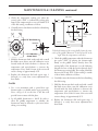
1
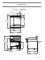
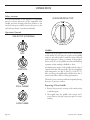
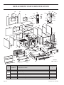
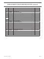
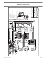
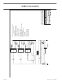
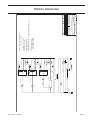
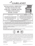
INSTALLATION & OPERATING
INSTRUCTIONS FOR THE
GARLAND® STARFIRE SENTRY COMBINATION
RANGE,
MODEL STW286A
FOR YOUR SAFETY
DO NOT STORE OR USE GASOLINE OR OTHER
FLAMMABLE VAPORS OR LIQUIDS IN THE
VICINITY OF THIS OR ANY OTHER APPLIANCE.
KEEP APPLIANCE AREA FREE AND CLEAR
FROM COMBUSTIBLES.
WARNING:
IMPROPER INSTALLATION, ADJUSTMENT,
ALTERATION, SERVICE OR MAINTENANCE CAN
CAUSE PROPERTY DAMAGE, INJURY OR DEATH.
READ THE INSTALLATION, OPERATION AND
MAINTENANCE INSTRUCTIONS THOROUGHLY
BEFORE INSTALLING OR SERVICING
THIS EQUIPMENT.
WARNING: ELECTRICAL GROUNDING INSTRUCTIONS
THIS APPLIANCE IS EQUIPPED WITH A THREE-PRONG (GROUNDING) PLUG FOR YOUR PROTECTION
AGAINST SHOCK HAZARD. IT SHOULD BE PLUGGED DIRECTLY INTO A PROPERLY GROUNDED THREEPRONG RECEPTACLE. DO NOT CUT OR REMOVE THE GROUNDING PRONG FROM THIS PLUG
DO NOT OBSTRUCT THE FLOW OF COMBUSTION AND VENTILATION AIR TO THIS APPLIANCE.
PLEASE READ ALL SECTIONS OF THIS MANUAL AND RETAIN FOR FUTURE REFERENCE.
THIS PRODUCT HAS BEEN CERTIFIED AS COMMERCIAL COOKING EQUIPMENT AND MUST BE INSTALLED BY
PROFESSIONAL PERSONNEL AS SPECIFIED.
For Your Safety:
Post in a prominent location, instructions to be followed in the event the user smells gas.
This information shall be obtained by consulting your local gas supplier.
Users are cautioned that maintenance and repairs must be performed by a Garland authorized service agent using genuine
Garland replacement parts. Garland will have no obligation with respect to any product that has been improperly installed,
adjusted, operated or not maintained in accordance with national and local codes or installation instructions provided
with the product, or any product that has its serial number defaced, obliterated or removed, or which has been modified
or repaired using unauthorized parts or by unauthorized service agents. For a list of authorized service agents, please refer
to the Garland web site at http://www.garland-group.com. The information contained herein, (including design and parts
specifications), may be superseded and is subject to change without notice.
Continuous product improvement is a Garland policy, therefore design and specifications are subject to change without notice.
GARLAND COMMERCIAL INDUSTRIES
185 East South Street
Freeland, Pennsylvania 18224
Phone: (570) 636-1000
Fax: (570) 636-3903
4517957
4517957Rev.
Rev.22(06/05)
(06/05)
GARLAND COMMERCIAL RANGES,
LTD.
1177 Kamato Road, Mississauga, Ontario L4W 1X4
CANADA
Phone: 905-624-0260
Fax: 905-624-5669
Enodis UK LTD.
Swallowfield Way, Hayes, Middlesex UB3 1DQ ENGLAND
Telephone: 081-561-0433
Fax: 081-848-0041
© 2005 Garland Commercial Industries,Page
Inc.
Page 4517957 Rev. 2 (06/05)
TABLE OF CONTENTS
DIMENSIONS . . . . . . . . . . . . . . . . . . . . . . . . . . . 4
SPECIFICATIONS . . . . . . . . . . . . . . . . . . . . . . . . 5
INTRODUCTION . . . . . . . . . . . . . . . . . . . . . . . 5
Unpacking: . . . . . . . . . . . . . . . . . . . . . . . . . . . 5
Rating Plate . . . . . . . . . . . . . . . . . . . . . . . . . . . 6
Safety . . . . . . . . . . . . . . . . . . . . . . . . . . . . . . . . 6
Product Usage . . . . . . . . . . . . . . . . . . . . . . . . . 6
INSTALLATION . . . . . . . . . . . . . . . . . . . . . . . . . 6
General Information . . . . . . . . . . . . . . . . . . . . 6
Clearances . . . . . . . . . . . . . . . . . . . . . . . . . . . . 7
Location . . . . . . . . . . . . . . . . . . . . . . . . . . . . . . 7
Appliances Equipped with Casters . . . . . . . . . . 7
Ventilation & Air Supply . . . . . . . . . . . . . . . . . 7
Gas Connection: . . . . . . . . . . . . . . . . . . . . . . . 8
Commissioning: . . . . . . . . . . . . . . . . . . . . . . . . 9
Burner Adjustments: . . . . . . . . . . . . . . . . . . . . . 9
Griddle /Solid Hot Top Burner . . . . . . . . . 9
Hot Top Minimum Flame Setting . . . . . . . 9
Oven Burner . . . . . . . . . . . . . . . . . . . . . . . 9
OPERATION . . . . . . . . . . . . . . . . . . . . . . . . . . . 10
Safety concerns . . . . . . . . . . . . . . . . . . . . . . . . 10
Operation Controls . . . . . . . . . . . . . . . . . . . . 10
Griddles . . . . . . . . . . . . . . . . . . . . . . . . . . . . . 10
Preparing A New Griddle . . . . . . . . . . . . . 10
Lighting The Griddle . . . . . . . . . . . . . . . . . 11
Seasoning The Griddle . . . . . . . . . . . . . . . . 11
Shut Down . . . . . . . . . . . . . . . . . . . . . . . . . 11
Solid Hot Tops (STW286A) . . . . . . . . . . . . . . 11
Lighting The Solid Hot Top . . . . . . . . . . . . 11
Oven . . . . . . . . . . . . . . . . . . . . . . . . . . . . . . . . 11
Convection Oven . . . . . . . . . . . . . . . . . . . 12
Lighting the Oven . . . . . . . . . . . . . . . . . . 12
Shut Down . . . . . . . . . . . . . . . . . . . . . . . . 12
Operating Suggestions . . . . . . . . . . . . . . . . . . 12
MAINTENANCE & CLEANING . . . . . . . . . . 12
Stainless steel . . . . . . . . . . . . . . . . . . . . . . . . . 12
Exhaust Filter . . . . . . . . . . . . . . . . . . . . . . . . . 13
Enameled/Painted Surfaces . . . . . . . . . . . . . . 13
Griddle . . . . . . . . . . . . . . . . . . . . . . . . . . . . . . 13
Cleaning instructions (After each use) . . . 13
Cleaning Instructions
(For Heavy Build Up) . . . . . . . . . . . . . . . 13
Griddle Do’s & Don’ts . . . . . . . . . . . . . . . 13
4517957 Rev. 2 (06/05)
Cleaning Burners . . . . . . . . . . . . . . . . . . . . . . 14
Griddle / Solid Hot Plate . . . . . . . . . . . . . 14
Convection Oven . . . . . . . . . . . . . . . . . . . 14
Pilot Burner Cleaning . . . . . . . . . . . . . . . 14
Gas Valve . . . . . . . . . . . . . . . . . . . . . . . . . . . . 14
Thermostat Calibration . . . . . . . . . . . . . . . . . 14
Oven . . . . . . . . . . . . . . . . . . . . . . . . . . . . 14
Griddle . . . . . . . . . . . . . . . . . . . . . . . . . . . . 15
Miscellaneous . . . . . . . . . . . . . . . . . . . . . . . . . 16
CONVERSION INSTRUCTIONS . . . . . . . . . . 16
FAULT FINDING . . . . . . . . . . . . . . . . . . . . . . . 17
REPLACEMENT OF PARTS . . . . . . . . . . . . . . 18
Gas Taps . . . . . . . . . . . . . . . . . . . . . . . . . . . . 18
Door Switch . . . . . . . . . . . . . . . . . . . . . . . . . . 18
Control Panel Rocker Switches . . . . . . . . . . . . 18
Thermostat . . . . . . . . . . . . . . . . . . . . . . . . . . . 18
Heat-On Lamp . . . . . . . . . . . . . . . . . . . . . . . 18
Gas Control Valve . . . . . . . . . . . . . . . . . . . . . 18
Front Cooling Fan . . . . . . . . . . . . . . . . . . . . . 19
Motor . . . . . . . . . . . . . . . . . . . . . . . . . . . . . . . 19
Ignition Control . . . . . . . . . . . . . . . . . . . . . . . 19
Hot Top Ignition Momentary Switch . . . . . . . 19
Hot Top Spark Generator . . . . . . . . . . . . . . . . 19
REPLACEMENT PARTS
IDENTIFICATION . . . . . . . . . . . . . . . . . . . . . . 20
WIRING DIAGRAMS . . . . . . . . . . . . . . . . . . . . 28
Page DIMENSIONS
3/4" NPT REAR
GAS INLET
FAN
GUARD
1 1/2"
[38mm]
10' POWER CORD
AT REAR [120V]
10 1/2"
[267mm]
3 3/4" [95mm]
3 1/2"
[83mm]
39 1/2"
[1003mm]
28"
[711mm]
5"
[127mm]
12"
[305mm]
24"
[610mm]
36"
[915mm]
45 1/2"
[1156mm]
31 3/4"
[806mm]
20 1/2"
[521mm]
5"
[127mm]
3/4" NPT REAR
GAS INLET
10' POWER CORD
AT REAR
32 1/2"
[825mm]
34"
[864mm]
Page 4517957 Rev. 2 (06/05)
SPECIFICATIONS
Oven Interior Dimensions
Entry Clearance
Installation Clearances
Height
Width
Depth
Crated
Uncrated
Sides
Rear
Shipping
Weight
Manifold
Inlet Size
13-12"
(343mm)
26-1/4"
(667mm)
22"
(559mm)
43"
(1105mm)
37-7/8"
(648mm)
7"
(178mm)
6"
(152mm)
584lbs.
(265kg)
3/4" NPT
Female
Input Ratings
Hot Top
Griddle
Operating Pressure
Oven
Total
Natural
Propane
BTU
kW
BTU
kW
BTU
kW
BTU
KW
"WC
mbar
"WC
mbar
25,000
7.32
50,000
14.65
30,000
8.79
105,000
30.76
4.5
11
10
25
NOTE: Installation clearance reductions are applicable only where local codes permit.
This product is not approved for residential use.
Commercial cooking equipment requires an adequate ventilation system. For additional information, refer to the National Fire Protection Association's standard NFPA96.
INTRODUCTION
This equipment must be installed and adjusted by a
competent person in accordance with the law. Failure
to install appliances correctly could lead to prosecution.
It is in your own interests and that of safety to ensure
that the law is complied with. Your Garland Dealer is
well qualified to provide this service.
2. The wires for retaining the burners and other
packing material must be removed from units. Any
protective material covering stainless steel parts
must also be removed.
This appliance should be given regular care and
maintenance. Periodic inspections by the dealer or a
qualified service company are recommended to check
temperature, burner adjustments and to ensure moving
parts are operative. Wherever possible avoid overheating
idle equipment as this is the primary cause of increased
service cost.
4. The type of gas and the supply pressure that the
equipment was set up for at the factory is noted on
the data plate and on the packaging. This type of
gas supply must be used.
“Regular maintenance ensures peak performance.”
Unpacking:
1. Check crate for possible damage sustained during
transit. Carefully remove unit from crate and again
check for damage. Any damage to the appliance
must be reported to the carrier immediately.
4517957 Rev. 2 (06/05)
3. All ranges are shipped from the factory with casters
fitted.
5. Do not remove permanently affixed labels, warnings
or data plates from the appliance, for this may
invalidate the manufacturer’s warranty.
NOTE: Many parts of the equipment are raw steel i.e
griddle top and solid hot top and can react with moisture
forming rust. This is normal and not considered a defect.
Clean with a stainless steel fiber pad. A light coating of
salt free oil may be applied to prevent further rusting.
Page INTRODUCTION continued
Rating Plate
All burner input ratings are shown on the name/rating
plate of each range which can be located behind the lower
front kick panel, (located below oven door). To access,
remove two (2) fasteners securing the panel shut.
For proper operation, the fuel information on the data
plate of your new equipment must match your fuel
supply.
When corresponding with the factory or equipment
dealer regarding service problems or replacement parts,
be sure to refer to the particular unit by the correct
model number, including prefix and suffix letters and
numbers and serial number. The rating plate affixed to
the unit contains this information.
Safety
It is essential that the instructions in this booklet are
strictly followed for the safe and economical operation
of the equipment. If it is known or suspected that a fault
exists on the appliance then it must not be used until
the fault is rectified by a competent person.
Power Failure Note: In the event of a power failure, no
attempt should be made to operate the oven. The oven
is gas operated but has electrical features, motor and
door switches.
Product Usage
The top of the range is designed for flexibility and the
preparation of numerous types of products.
Preparation of soups, stocks and sauces are done on a
hot top where slow even cooking is desirable. Heating
larger quantities of food can be done more efficiently than
heating small quantities. Pots and pans should be covered
whenever possible to reduce energy consumption.
High acid sauces, such as tomato should be cooked in
stainless steel vessels rather than aluminum since stainless
will not react chemically. Light coloured sauces may be
dicoloured by the aluminum especially if stirred with
a metal spoon. Salty water may pit aluminum vessels if
used frequently.
INSTALLATION
General Information
Before assembly and connection, check gas supply.
• The type of gas for which the unit is equipped is
stamped on the name/rating plate. Connect a unit
stamped “NAT” only to natural gas, and a unit
stamped “PRO” only to propane.
• In a new installation, have the gas authorities check
meter size and piping to ensure that the gas supply
will deliver sufficient pressure to operate the unit
properly.
• When adding or replacing equipment, have gas
authorities check gas pressure to ensure that the
Page existing meter and piping will supply fuel to the
appliance with no more than 0.5 inch water column
pressure drop during operation
• Before turning on the main gas supply, check the
unit to be certain that all the controls are in the
“OFF” position.
• When checking gas pressure, be sure that all other
equipment on the same gas line is turned “ON.”
A preset gas pressure regulator is supplied with
GARLAND Restaurant Series Equipment. It may
be necessary to adjust the regulator to deliver fuel at
the pressure shown on the rating plate.
4517957 Rev. 2 (06/05)
INSTALLATION continued
• In Canada, the installation must comply with local
codes, or in the absence of local codes, with the
Installation Codes for Gas Burning Appliances and
Equipment CAN/CGA-B149.1 and CAN/CGA
B149.2, (latest edition), and with the Canadian
Electrical Code C22.1 (latest edition).
Location
Appliances Equipped with Casters
In the United States the installation must comply
with the National Fuel Gas Code ANSI Z223.1,
(latest edition), NFPA No. 54, (latest edition), and
the National Electrical Code ANSI/NFPA 70,
(latest edition), and/or local codes to ensure a safe
and efficient operation.
• This equipment must be electrically grounded in
accordance with local codes, or in the absence of
local codes, with National Electrical Code, ANSI/
NFPA 70, or the Canadian Electrical Code, CSA
C22.2, as applicable.
• The appliance and its individual shut-off (supplied
by others) must be disconnected from the gas
supply piping system during any pressure testing of
the system at pressures in excess of 1/2 PSIG (3.45
KPA). The appliance must be isolated from the gas
supply piping by closing its individual manual shutoff (supplied by others) during any pressure testing
of the gas supply piping system at test pressures equal
to or less than 1/2 PSIG (3.45 KPA).
• Adequate clearance must be provided for servicing
and proper operation.
Clearances
Minimum installation clearance to adjacent combustible
walls and type of floor or base:
MINIMUM CLEARANCES STW286A
LOCATION
CLEARANCE
Left Hand Side
7" (178mm)
Right Hand Side
7" (178mm)
Rear
6" (152mm)
TYPE OF FLOOR OR BASE
Combustible
4517957 Rev. 2 (06/05)
The range should be installed on a firm, smooth and
level floor designed to withstand the weight of the fully
laden appliance. Any openings in the wall beside the
appliance should be sealed.
• The installation shall be made with a connector
that complies with the Standard for Connectors
for Moveable Gas Appliances, ANSI Z21.69/CGA
6.16, (latest edition), addenda Z21.69a-1989, and
a quick-disconnect device that complies with the
Standard for Quick Disconnects for Use with Gas
Fuel, ANSI Z21.41/CAN1 6.9, (latest edition).
• The front casters on the appliance are equipped
with brakes to limit the movement of the appliance
without placing any strain on the connector or
quick disconnect device or its associated piping.
• Be aware; required restraint is attached to a bracket,
which is located on the rear caster closest to the
gas connection. If disconnection of the restraint is
necessary, be sure to reconnect the device after the
appliance is returned to its original position.
Ventilation & Air Supply
The area in which the appliance is installed must be
adequately ventilated to provide air for combustion,
removal of products of combustion and removal of
steam, etc. Proper ventilation is essential for optimum
performance.
The ideal method of ventilating equipment is the use
of a properly designed canopy which should extend six
inches, (152mm), beyond all sides of the appliance(s) and
six feet, six inches, (1981mm), above the floor.
A strong exhaust will create a vacuum in the room. For
an exhaust vent to work properly, replacement air must
enter the room. The amount of air that enters must equal
the amount exhausted. All gas burners and pilots need
sufficient air to operate. Large objects should not be
placed in front of the appliance(s) which would obstruct
the flow of air into the front.
Page INSTALLATION continued
Gas Connection:
The gas pipe connection is made at the rear right hand
side of the equipment. The size of the pipe work supplying
the appliance must not be less than the inlet connection
which is 3/4” NPT. An isolating valve is recommended
to be close to the appliance to allow shut down during
an emergency or routine servicing. After installation, the
complete pipe work must be checked for soundness.
TABLE A. Gas Flow Rate (total)
NATURAL GAS ( ft3/h )
PROPANE GAS (ft3/h )
105
42
TABLE B. Heat Input Per Burner
NOMINAL HEAT INPUT
BURNER
NATURAL GAS
PROPANE
kW
BTU/HR
MJ/HR
kW
BTU/HR
MJ/HR
GRIDDLE
7.32
25,000
26.37
7.32
25,000
26.37
HOT TOP
7.32
25,000
26.37
7.32
25,000
26.37
OVEN
8.79
30,000
31.65
8.79
30,000
31.65
TABLE C. Manifold Pressure / Injector Size
NATURAL GAS
BURNER
Manifold Pressure
PROPANE
Injector Size
Manifold Pressure
Injector Size
mbar
"W.C.
DMS
mm
mbar
"W.C.
DMS
mm
GRIDDLE
11.2
4.5
42
2.4
25
10
53
1.51
HOT TOP
11.2
4.5
41
2.45
25
10
—
1.5
OVEN
11.2
4.5
35
2.8
25
10
51
1.7
NOTE: The pressure must be measured at the pressure test nipple located on the main manifold, located at the
left hand front of the range where the hot top valve is situated, with all burners lit.
TABLE D. Adjustment Pressure for “MIN” Valve Position (Hot Top section)
NATURAL GAS
PROPANE
mbar
"w.c.
mbar
"w.c.
2.0
0.8
4.5
1.8
NOTE: The pressure must be measured at the test nipple located downstream of the gas valve.
TABLE E. Aeration Shutter Setting / Pilot Flame Length
SHUTTER OPENING
BURNER
NATURAL GAS
PILOT FLAME LENGTH
PROPANE
mm
Ins.
mm
Ins.
mm
Ins.
OVEN
19
0.750
19
0.750
25.4
1
GRIDDLE
41.3
1.625
41.3
1.625
25.4
1
HOT TOP
41.3
1.625
41.3
1.625
12.5
0.5
Page 4517957 Rev. 2 (06/05)
INSTALLATION continued
Commissioning:
The whole of the gas installation, including the meter,
should be inspected, purged and tested for leakage in
accordance with local codes.
3. With a flat screwdriver, turn the adjuster on the
body of the tap clockwise to reduce the pressure or
anti-clockwise to increase pressure. Set the pressure
to correspond with table D.
1. Ensure that all controls are in the off position and
turn on the main gas supply and electrical mains.
PILOT
ADJUSTER
2. Remove the screws securing the front fascia and
connect a U-gauge manometer to the pressure test
point on the main manifold. Operate the main
burners in accordance with the instructions given
in the User’s manual.
3. Check that the setting pressure is correct per
TABLE C on the previous page. If necessary, adjust
the pressure governor located at the rear of the
range, downstream of the shut-off valve, to give the
required setting.
Griddle /Solid Hot Top Burner
Check that the aeration shutter is set to provide the
required opening per table E on the previous page. Adjust
if necessary.
FIXING SCREW
INJECTOR
LOCATION
Hot Top Minimum Flame Setting
1. Set the gas tap to the MIN position.
2. Connect a U-gauge manometer to the pressure test
nipple located downstream of the gas tap.
4517957 Rev. 2 (06/05)
TEST POINT
Oven Burner
1. Check that the aeration shutter is set to the required
opening per table E. Adjust if necessary.
Burner Adjustments:
SHUTTER
OPENING
MEASUREMENT
LOW FLAME
ADJUSTER
SHUTTER
OPENING
MEASUREMENT
When all the settings have been checked, remove the Ugauge manometer, replace the pressure test point screw
and the lower front panel.
Instruct the user or purchaser in the efficient and safe
operation of the appliance.
Tell the user of the location of the gas isolation cock
for use in an emergency. Leave this User Installation
and Servicing Instruction Manual with the user or
purchaser.
Page OPERATION
Safety concerns
OVEN/GRIDDLE TOP
It is the responsibility of the supervisor or equivalent
person to ensure that users of this equipment wear
suitable protective clothing and draw attention to the
fact that some parts will by necessity become very hot
and will cause burns if touched accidentally.
OFF
2
26
5
00
°F 440
1
450 400
150
Operation Controls
0
3
50
SOLID TOP (STW286A)
300 250 2
0
Griddles
OFF
IGNITION
Griddle tops are designed to have food cooked directly
on the surface. Do not put pots or pans on the griddle
surface as this will scratch or nick the surface and will
result in improper cooking or sticking of the product.
Never salt food over the griddle since this will build up
a gummy residue making it difficult to clean.
Avoid hitting the surface of the griddle with the edge of
a spatula since this will cause nicks. The most frequently
used temperatures are 300° F (149°C) to 350°(177°C).
After one firing, the griddle plate will discolour, this is
normal and will not affect cooking performance.
Check the grease container and drain frequently during
heavy use to prevent overflow.
FULL FLAME
Preparing A New Griddle
1. Remove the protective coating on the surface using
a mild detergent.
2. Thoroughly rinse the griddle with vinegar and a
water solution (3/4 cup vinegar per quart of water)
and dry.
LOW FLAME
Page 10
4517957 Rev. 2 (06/05)
OPERATION continued
Lighting The Griddle
NOTE: Ensure that the gas and electrical supply to the
appliance are turned “ON”. During the initial ignition
cycle, air must be purged from the gas line and thus it
may take two or three tries for ignition to occur.
1. Turn the power switch to the “ON” position.
2. Set the thermostat to the desired temperature.
3. If ignition fails and /or the ignition system goes into
lockout, set the power switch to the “O” position.
4. Wait five minutes and repeat steps 1 and 2. If
the problem persists have the unit checked by a
competent service technician.
Seasoning The Griddle
1. Use a clean cloth, rub a thin and even layer of oil
into the griddle surface. Oil should be an unsalted
shortening or high temperature cooking oil.
2. Set the griddle thermostat to 131°F (55°C) and heat
the griddle surface until the oil begins to caramelize
(turn a golden brow colour). Once this occurs, turn
the thermostat to “O”.
3. Scrape off the caramelized oil with a standard
spatula.
4. Repeat step 1 and set the griddle thermostat to
275°F (135°C).
5. Repeat steps 2 & 3. The griddle is now seasoned
and ready for use.
Shut Down
1. Set the thermostat to the lowest setting and turn
the power switch to the “O” position.
Solid Hot Tops (STW286A)
Recommended where long term stock pot cooking is
required for soups, sauces or stocks. Pots can be placed
anywhere on the hot top. The maximum recommended
stockpot size is 12” (305mm) in diameter
4517957 Rev. 2 (06/05)
The recommended pre-heat time is 30 minutes. This
will thoroughly saturate the plate. Pots must have flat
bottoms for maximum contact with the hot surface.
Roasting pans with straps should never be used on a top
since only the straps touch the surface and heat transfer
will be minimal.
Lighting The Solid Hot Top
1. Push in the tap and turn it anti-clockwise to the
ignition position “ ”
2. Holding the tap fully in, depress the ignitor switch
button and observe that the pilot lights. If it does
not, depress the ignitor switch button until it does.
3. When the pilot is lit, continue to hold the tap for 20
seconds, then release it. If the pilot extinguishes or
fails to hold, wait five (5) minutes and then repeat
step 1.
4. When the pilot is established, push the tap in again
and turn it anti-clockwise to the full flame position
“ ” thus lighting the main burner.
5. For low flame or simmer, push the tap in again
and turn it anti-clockwise to the low flame “ ”
position.
6. To shut the burner off, turn the dial to the “ ”
position and the safety device will disengage within
60 seconds.
Oven
The temperature is automatically controlled by the
thermostat so that satisfactory cooking can be repeated.
For the best performance the following instructions
should be followed.
GRID SHELVES – There are three shelf positions. The
shelf position is governed by the size of the product to be
cooked. Always push the shelf back into the oven until
it stops by making contact with the rear of the oven.
TRAY SIZE – A cake tray may be used on each shelf.
Single trays or dishes must not be allowed to overhang
the shelf in any direction, since this will adversely affect
the heat circulation.
Page 11
OPERATION continued
PREHEAT TIME – Allow at least 45 minutes after
turning the oven on from cold, with the thermostat at
the desired temperature before loading the oven with
food to be cooked. Put the food in quickly and close
the oven door.
4. Wait five minutes and repeat steps 1 and 2. If a
problem persists have the unit checked by a
competent technician.
Convection Oven
1. Set the thermostat to the lowest setting and turn
the power switch to the “O” position.
The forced air range oven consists of a food preparation
chamber completely sealed from the combustion area.
This permits an efficient method of circulating the heated
air within the cooking chamber.
Lighting the Oven
NOTE: Ensure that the gas and electrical supply to the
appliance are turned “ON”. During the initial ignition
cycle, air must be purged from the gas line and thus it
may take two to three tries for ignition to occur.
1 Turn the power switch to the “ON” position and
the Cook/cool switch to the “COOK” position.
2 Set the thermostat to the desired position.
Shut Down
Operating Suggestions
1. Turn the power switch to the “O” position when
the range is not in use.
2. Clean the range as soon as possible after cooking
tomato or vinegar based products that have a high
acid content. These foods can cause pitting of the
surface.
3. Allow the oven to preheat before adding product.
4. During an electrical power interruption, turn the
power switch to the “O” position. The oven cannot
be made to operate without electrical power
3. If ignition fails and or the ignition system goes into
lockout, set the power switch to the “O” position.
MAINTENANCE & CLEANING
Regular servicing by a competent person is recommended
to ensure the continued safe and efficient performance
of the appliance. The frequency will vary, depending on
the installation conditions and usage. Usually once per
year is adequate
WARNING: Turn off the gas supply to the appliance
at the service cock and the electrical mains before
commencing any servicing work.
IMPORTANT: Test for gas leakage on completion of
any servicing work.
A regular cleaning schedule should be established to
ensure efficient operation.
Page 12
WARNING: This appliance is not protected against
water jets. Do not clean with water jets.
Stainless steel
Stainless Steel should be cleaned using a mild detergent,
a soft cloth and hot water. If it is necessary to use a nonmetallic scouring pad, always rub in the direction of the
grain in the metal to prevent scratching. Wash a small
area at a time and rinse the washed area with a clean
sponge dipped into a disinfectant and wipe dry with a
soft clean cloth before it can dry.
4517957 Rev. 2 (06/05)
MAINTENANCE & CLEANING continued
Use only stainless steel, wood or plastic tools to scrape
off heavy deposits of grease or oil. Do not use ordinary
steel scrapers or knives as particles of iron my become
embedded and rust. NEVER USE STEEL WOOL.
1. Using a traditional 2.5”-3” (64mm-76mm) scraper
or spatula scrape the griddle surface (to remove food
particles and oil residues) towards the grease trough
using even back to front strokes.
Exhaust Filter
2. Apply griddle cleaner evenly over the griddle surface
and let it sit as directed. Follow the procedures on
the label of the specific cleaning product.
Inspect the front exhaust filter weekly, if on inspection
the filter appears dirty it can be cleaned by hand with
hot water and dish detergent. The filter is easily removed
by sliding out of the lower front panel of the unit.
Enameled/Painted Surfaces
Establish a regular cleaning schedule. Any spills should
be wiped off immediately. The unit should be allowed
to cool down before cleaning any exterior surfaces.
Wipe exposed cleanable surfaces when cool with mild
detergent and hot water. Stubborn residue spots may
be removed with a scouring pad. Dry thoroughly with
a clean cloth.
3. Using a traditional scraper or spatula, slosh around
the griddle cleaner to remove the build up.
4. Scrape the griddle surface towards the grease-trough
using even back to front strokes. Repeat step 2 if
necessary.
5. Using a mild detergent, clean the surface and rinse
thoroughly with water and vinegar solution, Dry
the griddle.
6. Using a clean cloth rub a thin and even layer of oil
into the griddle surface.
Griddle
7. Re-season the griddle as detailed in griddle
operation. The griddle is now ready for use.
Cleaning instructions (After each use)
Griddle Do’s & Don’ts
1. Use a traditional 2.5”-3” (64mm-76mm) scraper
or spatula to scrape the griddle surface (to remove
food particles and oil residues) towards the grease
trough using even back to front strokes.
Do’s
2. Pour shortening or oil onto the griddle surface using
a straight front to back motion. Clean the griddle
using a griddle stone or grill screen. Always wipe
with the grain of the steel, never sideways.
2. Keep the surface clean. Scraping the surface
throughout production to clear foods and oils
prevents build up and will make it easier to keep
the surface clean.
3. Using a clean cloth, rub a thin and even layer of oil
into the griddle surface.
3. Turn the temperature down during slow periods.
Reducing the temperature or turning sections
off during slow periods will conserve energy and
prevent the plate from over heating.
4. Remove the grease drawer, empty and wash
thoroughly with soap and water. Replace.
Cleaning Instructions (For Heavy Build Up)
NOTE: After using cleaners & grease cutter, re-season
the griddle
1. Season the griddle, This will prevent foods from
sticking and make it easier to keep the surface
clean.
Don’ts
1. Do not use salt to clean the griddle surface. Salt is
corrosive and can cause pitting of the griddle.
NOTE: Apply to a warm griddle for best results.
4517957 Rev. 2 (06/05)
Page 13
MAINTENANCE & CLEANING continued
2. Do not allow metal utensils (Spatula, scraper, etc.)
to nick and/or dent the surface of the griddle, The
edges of these utensils are sharp and will create
divots that oil can collect in and caramelize which
will cause sticking.
6. Clean the burner with a stiff scrubbing brush and
shake the burner well to ensure that ports are clear
of any debris.
3. Do not use the griddle as a hot top. A large pan
or pot will trap heat and cause the griddle plate to
warp.
Pilot Burner Cleaning
4. Do not overheat the griddle to preheat faster.
Preheating takes 15-20 minutes.
7. Reassemble in the reverse order.
1. Remove the main burners (refer to the section on
main burner cleaning).
2. Disconnect the pilot gas supply pipe from the pilot
jet.
Cleaning Burners
3. Remove the pilot jet.
Griddle / Solid Hot Plate
4. Clean by blowing through or washing. Do not use
wire to clear the pilot jet.
1. Lift off the griddle plate or solid hot top. Use caution:
This will require assistance due to the weight of the
griddle / solid hot top.
5. Reassemble in the reverse order.
2. Lift the rear of the burner and slide backwards off
the injector fitting.
Re-greasing of the gas taps is not recommended. If the
tap spindle becomes seized or difficult to turn, refer to
Replacement of Parts section in this manual.
3. Clean the burners in hot soapy water with a stiff
scrubbing brush.
4. Rinse and shake well to remove any debris.
Gas Valve
Thermostat Calibration
5. Reassemble in the reverse order.
Oven
Convection Oven
It is normal for a hydraulic thermostat cycling with a
temperature differential of 45° to 50°F. If the thermostat
is cycling beyond the 15° tolerance above or below the set
point and the appliance is under warranty, recalibrate the
thermostat or if not under warranty, consult owner for
proper action. If the thermostat is out of calibration more
than 50°, it will not likely hold an attempt of recalibration.
We suggest that the thermostat be replaced.
1. Open the lower kick panel.
2. Remove the left & right hand oven door springs.
USE CAUTION: the oven door will need additional
support to remain closed.
3. Remove the left and right hand radiation shields.
4. Remove the two (2) screws that secure the pilot
bracket and disconnect the pilot tubing at the union
connection.
5. Remove the injector support and slide the burner
and burner pan forwards out of the combustion
chamber.
Page 14
1. Place the thermocouple of the test instrument in
the center of the oven.
2. Turn the oven temperature control dial to 400°F. In
order to allow the oven temperature to stabilize, the
oven control must be allowed to cycle twice before
taking a test reading.
4517957 Rev. 2 (06/05)
MAINTENANCE & CLEANING continued
3. Check the temperature reading just when the
control cycles “OFF” as indicated by cycling pilot
lamp. If the temperature does not read within 15°F
of the dial setting, recalibrate as follows:
TOP VIEW
12.0
24.0
6.0
7.3
6.0
ref.
4. Carefully remove the thermostat dial, not disturbing
the dial setting.
28.0
11.5
Place
Thermocouple
Here
12.0
"B" Dial Shaft
HOT TOP
GRIDDLE
Decrease
36.0
FRONT
Increase
"A" Calibration
Screw Head
1/4
Turn
5. Hold the thermostat shaft steady and with a small
flat blade screw driver, turn the calibration screw
located inside the shaft clockwise to decrease the
temperature and anti-clockwise to increase the
temperature. Note: Each 1/4 turn of the screw will
create a change of approximately 25°F.
6. Replace the thermostat dial and repeat steps 1
through 3 to verify that correct adjustment has
been made.
Griddle
1. Use a test instrument with a special disc type
thermocouple or a reliable surface type pyrometer.
Note: a drop of oil on the face of the disc will
provide better contact with the plate.
2. Set all griddle thermostats to 300°F. In order to
allow the griddle temperature to stabilize, the
thermostats must be allowed to cycle twice before
taking a test reading.
4517957 Rev. 2 (06/05)
To find the location of the sensing bulbs, locate the exact
center of the griddle. Measure 6" to the left and 6" to the
right. Place the temperature sensor there.
3. Check the griddle temperature when the thermostat
just cycles “OFF” by placing the thermocouple
firmly on the griddle surface directly above the
sensing bulb of the thermostat. (see the following
diagram for how to find the location directly above
the thermostat sensing bulb) The reading should be
between 285°F and 315°F. If the reading is outside
of these limits, calibrate as follows:
4. Carefully remove the thermostat dial, not disturbing
the dial setting.
5. Hold the thermostat shaft steady and with a small
flat blade screw driver, turn the calibration screw
located inside the shaft clockwise to decrease the
temperature and anti-clockwise to increase the
temperature. Note: Each 1/4 turn of the screw will
create a change of approximately 25°F.
6. Replace the thermostat dial and repeat steps 1
through 3 to verify that correct adjustment has
been made.
Page 15
MAINTENANCE & CLEANING continued
Miscellaneous
1. Grease the door hinges and check for loose fasteners.
Tighten as necessary.
2. Wire brush the surface of the griddle to remove
baked on material, wash with hot water, dry
thoroughly. Lightly coat the surface with vegetable
oil to prevent rusting.
3. Wipe exposed cleanable surfaces with a mild
detergent and hot water. Stubborn residue may be
removed with a lightweight non-metallic scouring
pad. Stainless steel areas should be washed with
a mild detergent, hot water and a soft cloth. If
necessary to use a non-metallic scouring pad always
rub in the direction of the grain in the metal to
prevent scratching. NEVER USE STEEL WOOL.
4. Check the operation of the flame safety device by
closing the gas supply during burner operation.
Listen for the flame failure valve on the combination
gas control “clicking” closed. This action must
occur within 1 second of extinguishing the main
burner flame.
5. Clean the oven racks, shelves and guides with hot
soapy water and dry thoroughly. Clean the oven
interior with a propriety oven cleaner following the
manufacturers instructions.
CONVERSION INSTRUCTIONS
Servicing must be carried out by a competent person in
accordance with the law.
2. Remove the burners following the instructions
given in this manual.
WARNING: Turn off the gas supply to the appliance
at the service cock and the electrical mains before
commencing any servicing work.
3. Replace each injector fitting with the new fitting
that is supplied.
IMPORTANT: Test for gas leakage on completion of
any servicing work.
The following instructions are intended to describe
the operations necessary to convert equipment from
operation on one gas to another.
1. Ensure that all of the parts necessary to make the
conversion have been supplied as follows:
a. Injector fittings ( One required for each main
burner & one required for each pilot)
b. Regulator, (one per unit )
If any of the required parts are missing, contact
your Garland dealer before attempting to carry out
the conversion.
Page 16
NOTE: Before doing so, refer to Table C in this
manual to ensure that the correct injector has been
supplied for the gas supply being converted to.
4. Replace the spring in the governor with the new
spring supplied.
Upon completion of all the above operations, follow the
section in the manual on “Commissioning” and ensure
that the setting pressure and all burner flame settings
are adjusted accordingly.
4517957 Rev. 2 (06/05)
FAULT FINDING
PROBLEM
POSSIBLE CAUSES
SOLUTION
No power to oven.
Check power supply.
Defective Cook/Cool Down switch
Replace switch.
Faulty wiring.
Check condition of all wires & connections
Defective door switch.
Replace switch
Oven door partially open.
Close door.
Door switch out of alignment.
Align switch.
Defective motor.
Replace motor.
Faulty wiring.
Check condition of all wires & connections
Faulty motor relay
Replace relay
Combination gas valve not opening.
Defective thermostat replace.
Defective valve/thermostat
Replace valve/thermostat.
Blower wheel rubbing on oven baffle
Adjust blower wheel.
Blower wheel loose on motor shaft.
Retighten blower wheel.
Defective motor
Replace motor.
Defective Cook/Cool down switch.
Replace switch.
Defective door switch.
Replace switch.
Door switch out of alignment.
Align switch.
Faulty wiring.
Check condition of all wires & connections
Thermostat out of calibration.
Check calibration/replace thermostat.
Disconnected or loose hi voltage wires.
Reconnect hi voltage wires.
Defective DSI control module.
Replace DSI module
No power to oven
Check power supply.
Spark to igniter,thermostat set to
temperature. Burner does not go on.
Defective combination gas valve.
Replace valve.
Defective thermostat controller.
Replace controller
Oven doors will not stay closed.
Broken or damaged door spring
Replace door spring
Cook/Cool Down switch set to “Cook”
position. Light off. Motor not working.
Cook/Cool Down switch set to “Cook”
position. Light on motor not working.
Cook/Cool Down switch set to”Cook.”
Motor working thermostat set to
temperature, lamp “on,” oven not heating.
Noisy convection oven.
Cook/Cool Down switch set to “Cool
Down”, motor not working.
Oven too hot or not hot enough
No spark to igniter
Wiring Diagrams can be found at the end of this manual. A relevant schematic can be found on the inside of the
control panel when it is slid out for service.
4517957 Rev. 2 (06/05)
Page 17
REPLACEMENT OF PARTS
WARNING: Turn off the gas supply to the appliance
at the service cock and the electrical mains before
commencing any servicing work.
IMPORTANT: Test for gas leakage on completion of
any servicing work.
Gas Taps
1. Pull the knob off of each gas tap and thermostat on
the unit.
2. Remove the screws securing the fascia panel and
remove panel and grease drawer.
3. Remove the appropriate burner (if necessary)
following the procedure given in the section on
Main Burner Cleaning.
4. Disconnect the thermocouple connection at the gas
tap.
5. Disconnect the pilot and main burner tubing
connections at the gas tap.
6. Disconnect the tubing connection at the inlet of
the gas tap and remove the tap.
7. Replace with the new tap.
2. Slide out the control drawer to access the switch.
3. Disconnect the wires from the taps on the switch.
Be sure to note which wire connects to which
terminal on the switch.
4. Depress the tabs of the switch body and push the
switch through the opening in the control panel.
5. Replace the switch and reassemble in the reverse
order.
Thermostat
1. Remove the fastener securing
compartment access panel.
the
control
2. Slide out the control drawer to access the
thermostat.
3. Remove the dial from the thermostat and the screws
securing the thermostat body to the control panel.
4. Remove the wires from the thermostat terminals. Be
sure to note which wire connects to which terminal
on the thermostat.
5. Remove the thermostat sense bulb.
8. Reassemble in the reverse order.
6. Replace the faulty thermostat and reassemble in the
reverse order.
Door Switch
Heat-On Lamp
1. Remove the lower kick panel.
1. Remove the fastener securing
compartment access panel.
2. Disconnect the wires from the terminals on the
body of the switch.
the
control
2. Slide out the control drawer to access the lamp.
3. Remove the screws securing the door switch to the
mounting bracket and remove the door switch.
3. Disconnect the supply wires to the lamp body and
remove the faulty lamp.
4. Replace the faulty door switch.
4. Reassemble in the reverse order.
5. Make certain that the newly installed door switch
is properly adjusted so as to interrupt the power
supply to the gas control system and fan motor
when the oven doors are opened.
Gas Control Valve
Page 18
the
control
2. Slide out the control drawer.
Control Panel Rocker Switches
1. Remove the fastener securing
compartment access panel.
1. Remove the fastener securing
compartment access panel.
the
control
3. Remove the main body side panel to access the gas
train.
4517957 Rev. 2 (06/05)
REPLACEMENT OF PARTS continued
4. Break the pipe union connection at the inlet of the
gas control and the 7/16” union connection located
at the outlet of the control.
5. Remove the wires from the connections to the gas
valve. Be sure to note which wires connect to which
terminal before doing so.
7. Replace the control and reassemble in the reverse
order.
Front Cooling Fan
Ignition Control
1. Remove the fastener securing
compartment access panel.
the
control
2. Slide out the control drawer to access the lamp.
3. Disconnect the supply wires to faulty ignition
control (noting the wire connections)
4. Replace the faulty control.
6. Reassemble in the reverse order.
1. Remove fastener securing the control compartment
access panel.
Hot Top Ignition Momentary Switch
2. Slide out the control drawer.
2. Remove the fasteners securing the front panel.
3. Disconnect the fan supply harness form the unit
wiring harness.
3. Remove the nuts securing the switch box to the
front panel.
4. Remove fasteners retaining the fan and set aside.
4. Disconnect the 2 wires to the switch.
5. Replace the faulty motor.
5. Unscrew the switch from the front panel.
6. Reassemble in the reverse order.
6. Replace the switch and reassemble in reverse order.
Motor
Hot Top Spark Generator
1. Open the oven doors.
2. Remove the oven racks and guides.
1. Remove the fastener securing
compartment access panel.
3. Remove the two (2) wing screws securing the fan
guard and remove the guard.
2. Slide out the control drawer to access the generator
module.
4. Using an allen head wrench loosen the screw
securing the blower wheel to the motor shaft and
remove the wheel.
3. Disconnect the wires to the generator.
5. Remove the four (4) screws securing the motor
mount plate to the oven casing back and pull the
plate forward into the oven compartment.
1. Remove the griddle grease drawer.
the
control
4. Remove fastener retaining the generator.
5. Replace the faulty module and reassemble in reverse
order.
6. Disconnect the motor wire connections (note which
wire connects to which) and replace faulty motor.
8. Reassemble in the reverse order.
4517957 Rev. 2 (06/05)
Page 19
REPLACEMENT PARTS IDENTIFICATION
54
55
54
118
111
56
107
112
81
114
102
100
110
115
106
113
103
104
109A
109
105
52
51
57
29
28
108
30
31
50
48
101
49
23 21
233
82
43
31
47
46
42
86
83
95
96
42
41
98
40
32
5
35
36
44
58
74 63
3
73
70
79
69
59
66
62
DESCRIPTION
16
15
53
4
33
4A
1
11
232
8
89 17
88 18
13 2 12
120 19
6 166
64A 7
67
68
20
116
117
66
60
87
22
24
25
SK3894
SHT. 1 OF 2
ITEM
PART No
1
076050-87
1/4 Compression Union
1
2
076050-88
7/16 Compression Union
1
3
1005800
Door Spring
2
2206513
Oven Spark Ignition Pilot NAT
1
2206512
Oven Spark Ignition Pilot PRO
1
4
4A
Page 20
45
65
64
71
37
36
80
78
93
61
76
75
26
14
92
38
39
77
32
34
91
97
90
41
27
27
94
STW286A
Oven Pilot Orifice (Specify Gas)
1
5
4518183
Pilot Bracket, Oven
1
6
22701XX
Oven Orifice Fitting
3
4517957 Rev. 2 (06/05)
Replacement Parts IDENTIFICATION continued
ITEM
PART No
7
M9-XX
DESCRIPTION
STW286A
Oven Orifice Hood (Specify Gas)
1
8
2635100
Oven Orifice Support Bracket
1
11
2624900
Tube ¼ - Oven Pilot to ¼ Compression Union
1
12
2642800
Sensor Wire
3
13
2624800
Tube 7/16 – 7/16 Oven Orifice to Compression Union
1
14
4518182
Oven Burner
1
15
1390702
RH Roll Out Shield
1
16
1391100
Roll Out Shield Support
1
17
4518184
LH Roll Out Shield
1
18
2512700
Lower Front Plate
1
19
2628699
Kick Panel Bracket
2
20
4517059
Kick Panel
1
21
2622200
Front Support
1
22
G01487-8
Heyco Bushing
1
23
2604400
RH Door Filler
1
24
1083001
Trunion Support
2
25
1082700
Harness Ring
2
26
1730296
Front Frame Assy
1
27
2621300
Body Side Support
2
28
2614100
Body Side R/H
1
29
2642000
Wall Shield
1
30
2604200
Inner Liner
1
31
1309021
Body Side Insulation - .5” Thick (Burglas 1200)
2
32
3020000
Side Insulation Pan
2
33
3019900
Flue Spacer Angle
6
34
G02905-01-8E Capillary Guard Assy
1
35
1402400
Casing Support Angle
2
36
1325900
Fire Plate Rear Support
2
37
1411302
Casing Support RH
1
38
1411303
Casing Support LH
1
39
3019701
Casing Bottom
1
40
1311100
Rack Guide Assy - LH
1
41
1356600
Rack Guide Clip
4
42
1411700
Insulation Support
2
43
2301200
Oven Rack
2
4519087
Divided Oven Rack
1
44
1357702
Fire Plate
1
45
1412098
Fire Plate Front Support Bracket Assembly
1
46
3019601
Casing Back
1
47
2614101
Body Side LH
1
48
3014099
Main Back Insulation Pan Assy
1
49
3019898
Casing Top
1
50
3020199
Top Insulation Pan Assy
1
51
1309025
Insulation - Oven Cavity Top Front
1
4517957 Rev. 2 (06/05)
Page 21
Replacement Parts IDENTIFICATION continued
PART No
52
1309022
Insulation - Oven Cavity Top Rear
1
53
2677600
LH Roll Out Shield Aupport
1
54
1472202
Insulation - Oven Cavity Rear Sides
2
55
2621199
Flue Riser Assy
1
56
3013900
Main Back
1
57
1472200
Insulation - Cavity Back
1
58
2620800
Main Bottom
1
59
2301300
Door Spring Support
1
60
2620900
Main Bottom Support Channel
2
61
1311101
Rack Guide Assy - RH
1
62
1386100
Bell Crank Support
2
63
1082803
Oven Door Hinge Link LH
1
64
1082198
LH Bell Crank
1
64A
1082199
RH Bell Crank
1
65
1082200
Bell Crank Bolt
2
66
9004701
Oven Door Spring Hook
2
67
1082802
Oven Door Hinge Link RH
1
68
G01503-16
Weld Stud 1/4-20 x 1.75
1
69
1439901
Oven Door Panel
1
70
3077100
Nameplate
1
71
3017000
Handle
1
4516836
120V Cooling Fan Assembly
1
4517669
230 V Cooling Fas Assembly
1
73
3007300
Handle End
2
74
3010000
Handle End Plastic Insert
2
75
1082500
Oven Door Trunion
2
76
G03984-03-8
Oven Door Insert Assy
1
77
1439796
Oven Door Lining
1
78
1472303
Insulation - Oven Door Interior Lower Section
1
79
1472301
Insulation - Oven Door Interior Middle Section
1
80
1472302
Insulation - Oven Door Interior Upper Section
1
81
2519799
Motor Guard Assy
1
2485801
Motor 115V
1
2485800
Motor 208/240V
1
83
G01503-3
Ohio Weld Nut 1/4-20
8
86
G01497-1
BX Connector Straight
2
87
4519840
Casters, Swivel, Locking
2
88
4519839
Casters, Swivel
2
89
1748701
Restraint Attachment Bracket
1
90
1361299
Air Baffle Support Assy
2
91
F542
Aluminum Padded Washer
2
92
F543
Stainless Steel Wing Screw
2
93
2520100
Fan Protector Screen
1
94
2395999
Air Baffle Assy
1
72
82
Page 22
DESCRIPTION
ITEM
STW286A
4517957 Rev. 2 (06/05)
Replacement Parts IDENTIFICATION continued
123
126
124
121
136
134
132
128
135
125
122
133
130
197
145
131
129
143
152
144
142
146
147
141
139
127
138
148
140
165
159
158
155
156 157
12 163
201
170
174
180
187
198
173
178
172 171
226
208 177
235
179
176
213
202 175
219
220
169
215
227
200
221
207
222
199
205
203
119
206
174
225
241
137
211
239
212
201
217
204
209
218
216
214
72
4517957 Rev. 2 (06/05)
153
234 242
168
167 12
164
6
160
161 181
210
151
149
162
154
150
185
166
165A
182
183
186
184
236
237
189
230
190
229
239
192
191
188
193
240
194
195
196
SK3894A
SHT. 2 OF 2
Page 23
Replacement Parts IDENTIFICATION continued
PART No
95
1669101
Motor Pocket Insulation Board
1
96
3013301
Motor Mount Pocket
1
97
3013401
Motor Mount Plate
1
98
G02952-01P
Blower Wheel
1
100
2640700
Manifold Support Bracket
2
101
2640800
Manifold Support Clamp
2
102
G01474-5
3/4” NPT Elbow
1
103
G01738-14
Nipple 3/4” NPT X 2” (Domestic Model)
1
104
G01518-1
Valve-Swing Type Shut Off Gas (Domestic Model)
1
105
G01738-9
Nipple 3/4” NPT X 9.5” (Domestic Model)
1
106
G01738-13
Nipple 3/4” NPT X 13.5” (Export Model)
1
107
G01475-2
3/4” NPT 90 Deg. Street Elbow
3
2127502
Gas Regulator (NAT) (Domestic Model)
1
108
STW286A
2127500
Gas Regulator (PRO) (Domestic Model)
1
109
2525200
Jeavons Regulator (NAT) (Export Model)
1
109A
2525300*
Regulator Spring (PRO)
1
110
2622400
Wiring Access Cover
1
111
4517369
Control Compartment Back
1
112
2490500
Straight Thru Relief Bushing (Domestic Model)
1
113
1029600
Antishorts
2
114
1029400
3/8” BX Cable
1
115
1028500
BX Connector - 90 Deg.
2
116
4517402
Door Switch Bracket/Heat Shield
1
117
2628000
Door Switch
1
117A
3096100*
Door Switch Wiring Harness
1
118
G01738-4
Nipple 2.5”
1
2621400
Oven/Griddle Dial Insert Fahrenheit
3
119
Page 24
DESCRIPTION
ITEM
2621401
Oven/Griddle Dial Insert Celsius
3
120
2620700
Lifting Angle
2
121
2615900
Burner Box Back
1
122
1414600
Burner Box Back Support
1
123
2374301
Backguard Top 36”
1
124
2614200
Backguard Back
1
125
2374101
Backguard Front
1
126
2629400
Griddle Splash Shield
1
127
2614398
Burner Box Side Assy LH
1
128
2614399
Burner Box Side Assy RH
1
129
2604799
Hot Top Assy
1
130
4517072
Griddle Assy
1
131
2616100
Drip Tray Guide
1
132
2616000
Drip Tray Stop
1
133
4516888
Drip Tray
1
134
2618000
Grease Trough
1
135
4516885
Grease Drawer Assy
1
4517957 Rev. 2 (06/05)
Replacement Parts IDENTIFICATION continued
DESCRIPTION
ITEM
PART No
136
4516887
Grease Sleeve
1
137
4517610
Thermostat - Oven
1
138
1014900
Cast Iron H-Burner
3
139
1028002
Air Shutter (Hot Top Burner)
1
140
2512100
Air Shutter (Griddle Burner)
2
141
4517190
Bulb Clamp/Shield Assy
2
142
2614500
Burner Box Bottom
1
143
4517373
Heat Shield-Tubing
1
144
2619400
Insulation Shield
2
145
2642100
Control Compartment Top Insulation
1
146
2608100
Insulation Retainer
1
147
1085000
Burner Box Front Channel 36”
1
148
4517408
Grease Chute Front
1
149
4517409
Grease Chute Back
1
150
2618100
Grease Deflector
1
151
4516890
False Handle
1
152
4516884
Heat Shield - Upper Tubing
1
153
2615700
Panel Stop
1
154
2614698
Hot Top Burner Box Assy
1
155
2617500
Orifice Support Hot Top
1
156
M8-XX
Orifice Hood - Hot Top (Specify Gas)
1
157
G02486-00
Orifice Fitting less Hood (Hot Top)
1
158
2200700
SIT Pilot RH
1
158A
2200704
3/16” Comp Nut
1
158B
2200705
Olive Ball Sleeve
1
158C
2200706
Nut Thermo Retaining
1
158D
2200707
Nut Electrode
1
158E
2200708
Electrode
1
159
2200600
18” Thermocouple - Hot Top
1
160
2614900
Bracket - Hot Top Pilot
1
2200702
Orifice - Hot Top Pilot #32 (NAT)
1
2200703
Orifice - Hot Top Pilot #23 (PRO)
1
162
4516665
Griddle Burner Box Assy
1
163
2617400
Orifice Support –Griddle
2
161
164
165
M9-XX
STW286A
Orifice Hood - Griddle (Specify Gas)
2
2206514
Griddle Spark Ignition Pilot (PRO)
2
2206515
Griddle Spark Ignition Pilot (NAT)
2
Griddle Spark Ignition Pilot Orifice (Specify Gas)
2
165A
166
1466100
Flame Sensor
3
167
2614800
Griddle Pilot Bracket
2
168
4517038
Heat Shield - Griddle Burner Box
1
169
2617000
Main Manifold Retainer Bracket
1
170
2612399
Sub-Manifold Assembly
1
171
2200199
Valve (Hot Top)
1
4517957 Rev. 2 (06/05)
Page 25
Replacement Parts IDENTIFICATION continued
PART No
172
2198102
Valve Connector Fitting 10mm
1
173
2203400
1/8” NPT Plug
2
174
G02251-1
Pressure Test Spigot
2
175
G01243-1
Fitting 68-7B
1
176
1086597
Gum Valve – 3/16” Pilot
1
177
4517599
Tube (¼”) - Hot Top Valve to Hot Top Orifice Fitting
1
178
2625000
Tube (3/16”) - Hot Top Valve to Hot Top Pilot
1
179
2624700
Tube (7/16”) -Oven Solenoid Valve to 7/16 Compression Coupling
1
180
2619100
Tube (7/16”) –Manifold to Sub Manifold
1
181
2624600
Tube (¼”) -Oven Solenoid Valve to (¼) Compression Coupling
1
182
4517601
Tube (¼”) –Solenoid Valve to Griddle Pilot LH
1
183
4517602
Tube (7/16”) –Solenoid Valve to Griddle Burner Orifice LH
1
184
4517603
Tube (7/16”) –Solenoid Valve to Griddle Burner Orifice RH
1
185
4517600
Tube (1/4”) –Solenoid Valve to Griddle Pilot RH
1
186
4517062
Front Rail
1
187
4517039
Heat Shield - Hot Top Valve
1
188
G03053-1
Momentary Push Button Switch
1
189
4516937
Handle Assy
1
190
4517048
Valve Panel
1
191
4517416
Switch Box
1
192
4517417
Switch Box Cover
1
193
4517061
Hot Top Overlay
1
194
G0728-1-8
Thermostat Guard
1
195
3043100
Valve Knob
4
196
2310000
Dial Insert (Hot Top)
1
197
2615802
Flue Box
1
198
2642200
Coiled Cord (Domestic Model)
1
199
2612299
Main Manifold
1
200
2621500
Valve Connector Fitting (7/16”)
3
201
1095499
3/8 NPT to 7/16 Comp Fitting
5
202
G03674-3
Valve -Pilot ¼” Angle 90Deg
3
203
G02352-1
Elbow 3/8 NPT to 7/16cc Male
2
204
2619500
Solenoid Valve 24v
3
205
2475700
Relay Clip
1
206
2672200
Relay
1
207
2475600
Relay Base
1
208
2617300
Component Side Support
1
209
2613300
Component Support
1
210
2613400
Component Slide
1
211
2619600
Pilot Ignition Control 24V
3
212
2573000
Terminal Block 3 Circuit
2
213
4517609
Thermostat - Griddle
2
2652401
75VA Transformer (120V)
1
2652402
75VA Transformer (208/240V)
1
214
Page 26
DESCRIPTION
ITEM
STW286A
4517957 Rev. 2 (06/05)
Replacement Parts IDENTIFICATION continued
DESCRIPTION
ITEM
PART No
215
4516857
Control Panel
1
216
4517060
Overlay - Control Panel
1
217
2629000
Oven Control Cover
1
218
2628700
Oven Control Cover Support
1
219
2630200
Switch SPDT ON-OFF-ON
1
220
2146800
Illuminated Power Switch
1
221
2667200
Pilot Assy Amber
3
222
4517756*
Extra 7/16” c.c. Hardware
1
4514749
Spark Generator - 230V, 4 outlet
1
4514750
Spark Generator - 120V, 4 outlet
1
3050401
Terminal Block (Export Model)
1
227
4517052
BX-Connector Retainer
1
229
G03883R
Thermoflex Insulating Sleeve
1
230
2200203
High Tension Wire Lead 64”
1
232
4520038
Vent Cover
1
233
4520028
Exhaust Fan Filter Frame/Screen
1
234
4516839
Exhaust Fan Filter
1
235
4517051
Capillary Heat Shield
1
236
4516938
Handle End
2
237
4517424
Front Rail Support Bracket - RH
1
239
3043300
Spring Retainer
4
240
3043202
Hot Top Valve Knob Hub
1
241
3043207
Griddle/Oven Valve Knob Hub
3
242
4520024
Filter Cover
1
243
G01500-1
Ground Terminal (230V)
1
225
226
STW286A
* NOT ILLUSTRATED
4517957 Rev. 2 (06/05)
Page 27
53
52
1431526
PV3
1431526
GRIDDLE RIGHT VALVE
PV2
1431526
15
36
9
13
WHITE
14
PV1
3
GRIDDLE LEFT VALVE
OVEN MOTOR
M~
COOLING FAN
M~
GREEN
8
44
40
37
10
43
12
11
52
39
10
45
8
5
51
53
4
1
FLAME SENSOR
SPARK ELECTRODE
E3
T1
11
18
F3
16
RELAY RL1
31
50
BLACK
COM
WHITE 120V
ORANGE 240V
RED 208V
9
OVEN VALVE
MV3
41
MV2
35
MV1
SELECT
J2
1434533
1431528
4
2
SPARK
CTL3
SP 845
13
14
48
12
9
29
19
30
7
6
17
45
44
34
43
18
FLAME SENSOR
31
46
E2
M
V
38
36
P
V
11
39
8
7
33
20
SPARK
41
29
19
30
18
P
T
G
V
R
/
N
M GND D
V
6
5
35
40
32
T
L
H
E
D 24V
OMRON
BASE
SP 845
4
3
ALTERNATE
RELAY CONNECTION
12
2
1
37
CTL1
19
SPARK
ELECTRODE F2
17
24
S
E
N
S
E
P
T
G
V
R
/
N
M GND D
V
T
L
H
E
D 24V
P
V
M
V
42
CTL2
S
E
N
S
E
E1
GRIDDLE RIGHT
THERMOSTAT
TH1
GRIDDLE LEFT
THERMOSTAT
34
31
33
32
26
26
FLAME SENSOR
II
OVEN THERMOSTAT
TH2
21
TH3
F1
I
0
24
25
25
OFF
30
SW2
46
42
38
COOL
COOK
COOK/COOL SWITCH
SPARK ELECTRODE
48
PL3
PL2
PL1
27
28
5
23
22
21
7
6
49
SW1
29
OFF
ON
28
0
I
27
POWER SWITCH
N
49
CO
5
N
1
S
E
N
S
E
1431526
SPARK
P
T
G
V
R
/
N
M GND D
V
J1
T
L
H
E
D 24V
1431531
SP 845
P
V
Page 28
M
V
BLACK
SW3
54
48
47
55
55
55
49
DR.
DATE
NA
SCALE :
1
OF
2
4517604
SHT
REV.#
STW286A
NOV 29/97
DATE :
WIRING DIAGRAM STW286A
CHK. BY :
ALL DIMENSIONS ARE IN INCHES
TOLERANCE ±0.015" UNLESS OTHERWISE SPECIFIED
REVISIONS
DESCRIPTION
SWITCH BOX
1 2 3
E N L
V.C.
47
TITLE:
DR. :
REV
48
IGNITION MODULE
HOT TOP
HOT TOP SPARK ELECTRODE
E4
TOTAL MAXIMUM LOAD:
120V 50/60Hz, 4.5 AMPS
230V 50/60Hz, 2.3 AMPS
HOT TOP IGNITION MODULE
100-120V 0.6VA
220-240V 0.8VA
SP845 IGNITION MODULE:
24V, 50/60Hz, 0.25A
FLAME SENSE CURRENT 0.7 MICROAMPS MINIMUM REQUIRED
SOLENOID VALVES (EACH):
24V, 50/60Hz, 0.4A MAX.
PAPST COOLING FAN:
115V MODEL 4606N 50/60 HZ, 18W
230V MODEL 4656N 50/60 HZ, 18W
MOTOR: 1/3hp, 115V, 50/60Hz, 3.6 AMP,
230V, 50/60Hz, 1.8 AMP
WIRING DIAGRAMS
4517957 Rev. 2 (06/05)
x3
53
52
x2
1431526
PV3
1431526
GRIDDLE RIGHT VALVE
PV2
1431526
15
36
9
13
WHITE
14
PV1
3
GRIDDLE LEFT VALVE
OVEN MOTOR
M~
COOLING FAN
M~
E
N
8
44
40
37
10
43
12
11
52
39
10
45
8
5
51
53
4
1
FLAME SENSOR
SPARK ELECTRODE
E3
T1
11
18
F3
16
RELAY RL1
31
50
BLACK
COM
WHITE 120V
ORANGE 240V
RED 208V
9
OVEN VALVE
MV3
41
MV2
35
MV1
SELECT
J2
1434533
1431528
4
2
SPARK
CTL3
SP 845
13
14
12
9
29
48
19
30
7
6
17
45
44
34
43
18
FLAME SENSOR
31
46
E2
M
V
38
36
P
V
11
39
8
7
33
20
SPARK
41
29
19
30
18
P
T
G
V
R
/
N
M GND D
V
6
5
35
40
32
T
L
H
E
D 24V
OMRON
BASE
SP 845
4
3
ALTERNATE
RELAY CONNECTION
12
2
1
37
CTL1
19
SPARK
ELECTRODE F2
17
24
S
E
N
S
E
P
T
G
V
R
/
N
M GND D
V
T
L
H
E
D 24V
P
V
M
V
49
42
CTL2
S
E
N
S
E
E1
GRIDDLE RIGHT
THERMOSTAT
TH1
GRIDDLE LEFT
THERMOSTAT
34
OVEN THERMOSTAT
TH2
21
TH3
F1
31
33
32
26
26
FLAME SENSOR
II
0
I
24
25
25
OFF
30
SW2
46
42
38
COOL
COOK
COOK/COOL SWITCH
SPARK ELECTRODE
48
PL3
PL2
PL1
27
28
5
23
22
21
7
6
49
SW1
29
OFF
ON
28
0
I
27
POWER SWITCH
N
5
CO
1
N
1431526
S
E
N
S
E
J1
SPARK
P
T
G
V
R
/
N
M GND D
V
x1
T
L
H
E
D 24V
L1
SP 845
P
V
4517957 Rev. 2 (06/05)
M
V
1431531
SW3
54
48
47
55
55
55
49
DR.
DATE
NA
SCALE :
DATE :
1
OF
2
4517606
SHT
REV.#
STW286A
DEC 10/2003
WIRING DIAGRAM STW286A
CHK. BY :
ALL DIMENSIONS ARE IN INCHES
TOLERANCE ±0.015" UNLESS OTHERWISE SPECIFIED
REVISIONS
DESCRIPTION
SWITCH BOX
1 2 3
E N L
N.B.
47
TITLE:
DR. :
REV
47
IGNITION MODULE
HOT TOP
HOT TOP SPARK ELECTRODE
E4
TOTAL MAXIMUM LOAD:
120V 50/60Hz, 4.5 AMPS
230V 50/60Hz, 2.3 AMPS
HOT TOP IGNITION MODULE
100-120V 0.6VA
220-240V 0.8VA
SP845 IGNITION MODULE:
24V, 50/60Hz, 0.25A
FLAME SENSE CURRENT 0.7 MICROAMPS MINIMUM REQUIRED
SOLENOID VALVES (EACH):
24V, 50/60Hz, 0.4A MAX.
PAPST COOLING FAN:
115V MODEL 4606N 50/60 HZ, 18W
230V MODEL 4656N 50/60 HZ, 18W
MOTOR: 1/3hp, 115V, 50/60Hz, 3.6 AMP,
230V, 50/60Hz, 1.8 AMP
WIRING DIAGRAMS
Page 29
Page 30
L1
SW1
POWER
OFF
SW2
COOL
COOK
M~
RL1a
5(3)
4A
NC
CTL3
120V ~
24V ~
SW3
COM
PB
NO
IGN
MV
PV
TH
GND
SENSE
IGN
12(6)
T1
MV
PV
TH
GND
SENSE
IGNITION CONTROL
CTL2
OVEN
MV
PV
TH
GND
SENSE
IGNITION CONTROL
CTL1
DOOR SWITCH
TH3
GRIDDLE RIGHT
COOLING FAN
COOK-COOL SWITCH
13(7)
TH2
TH1
GRIDDLE LEFT
IGN
IGNITION CONTROL
RL1b
M~
RL1
14(8)
PL3
MV3
PV3
PL2
MV2
PV2
PL1
MV1
PV1
SPARK ELECTRODE HOT TOP
IGNITION MODULE HOT TOP
8(4)
13(7)
FLAME SENSOR
SPARK ELECTRODE
FLAME SENSOR
SPARK ELECTRODE
FLAME SENSOR
SPARK ELECTRODE
N
TOTAL MAXIMUM LOAD:
120V 50/60Hz, 4.5 AMPS
230V 50/60Hz, 2.3 AMPS
HOT TOP IGNITION MODULE
100-120V 0.6VA
220-240V 0.8VA
TITLE:
DR. :
REV
SP845 IGNITION MODULE:
24V, 50/60Hz, 0.25A
FLAME SENSE CURRENT 0.7 MICROAMPS
MINIMUM REQUIRED
SOLENOID VALVES (EACH):
24V, 50/60Hz, 0.4A MAX.
PAPST COOLING FAN:
115V MODEL 4606N 50/60 HZ, 18W
230V MODEL 4656N 50/60 HZ, 18W
MOTOR: 1/3hp, 115V, 50/60Hz, 3.6 AMP,
230V, 50/60Hz, 1.8 AMP
DR.
DATE
NA
SCALE :
ALL DIMENSIONS ARE IN INCHES
CHK. BY :
DATE :
OF
4517605
SHT
REV.#
STW286A
DEC 10/2003
SCHEMATIC DIAGRAM, 120V
N.B.
TOLERANCE ±0.015" UNLESS OTHERWISE SPECIFIED
REVISIONS
DESCRIPTION
WIRING DIAGRAMS
4517957 Rev. 2 (06/05)
4517957 Rev. 2 (06/05)
L1
SW1
POWER
OFF
SW2
COOL
COOK
M~
RL1a
5(3)
4A
NC
CTL3
230V ~
24V ~
SW3
COM
PB
NO
IGN
MV
PV
TH
GND
SENSE
IGN
12(6)
T1
RL1b
thermodisc
MV
PV
TH
GND
SENSE
IGNITION CONTROL
CTL2
OVEN
MV
PV
TH
GND
SENSE
IGNITION CONTROL
CTL1
DOOR SWITCH
TH3
GRIDDLE RIGHT
COOLING FAN
COOK-COOL SWITCH
13(7)
TH2
TH1
GRIDDLE LEFT
IGN
IGNITION CONTROL
M~
RL1
14(8)
PL3
MV3
PV3
PL2
MV2
PV2
PL1
MV1
PV1
SPARK ELECTRODE HOT TOP
IGNITION MODULE HOT TOP
8(4)
warning light
13(7)
FLAME SENSOR
SPARK ELECTRODE
FLAME SENSOR
SPARK ELECTRODE
FLAME SENSOR
SPARK ELECTRODE
N
TOTAL MAXIMUM LOAD:
120V 50/60Hz, 4.5 AMPS
230V 50/60Hz, 2.3 AMPS
TITLE:
DR. :
REV
DR.
DATE
NA
SCALE :
ALL DIMENSIONS ARE IN INCHES
CHK. BY :
OF
4517607
SHT
REV.#
STW286A
DEC 8/97
DATE :
SCHEMATIC DIAGRAM, 230V
VC
TOLERANCE ±0.015" UNLESS OTHERWISE SPECIFIED
REVISIONS
DESCRIPTION
SP845 IGNITION MODULE:
24V, 50/60Hz, 0.25A
FLAME SENSE CURRENT 0.7 MICROAMPS MINIMUM REQUIRED
SOLENOID VALVES (EACH)
24V, 50/60Hz, 0.4A MAX.
MOTOR: 1/3hp, 115V, 50/60Hz, 3.6 AMP
230V, 50/60Hz, 1.8 AMP
WIRING DIAGRAMS
Page 31