1
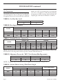
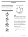
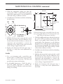
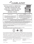
INSTALLATION continued
Commissioning:
The whole of the gas installation, including the meter,
should be inspected, purged and tested for leakage in
accordance with local codes.
3. With a flat screwdriver, turn the adjuster on the
body of the tap clockwise to reduce the pressure or
anti-clockwise to increase pressure. Set the pressure
to correspond with table D.
1. Ensure that all controls are in the off position and
turn on the main gas supply and electrical mains.
PILOT
ADJUSTER
2. Remove the screws securing the front fascia and
connect a U-gauge manometer to the pressure test
point on the main manifold. Operate the main
burners in accordance with the instructions given
in the User’s manual.
3. Check that the setting pressure is correct per
TABLE C on the previous page. If necessary, adjust
the pressure governor located at the rear of the
range, downstream of the shut-off valve, to give the
required setting.
Griddle /Solid Hot Top Burner
Check that the aeration shutter is set to provide the
required opening per table E on the previous page. Adjust
if necessary.
FIXING SCREW
INJECTOR
LOCATION
Hot Top Minimum Flame Setting
1. Set the gas tap to the MIN position.
2. Connect a U-gauge manometer to the pressure test
nipple located downstream of the gas tap.
4517957 Rev. 2 (06/05)
TEST POINT
Oven Burner
1. Check that the aeration shutter is set to the required
opening per table E. Adjust if necessary.
Burner Adjustments:
SHUTTER
OPENING
MEASUREMENT
LOW FLAME
ADJUSTER
SHUTTER
OPENING
MEASUREMENT
When all the settings have been checked, remove the Ugauge manometer, replace the pressure test point screw
and the lower front panel.
Instruct the user or purchaser in the efficient and safe
operation of the appliance.
Tell the user of the location of the gas isolation cock
for use in an emergency. Leave this User Installation
and Servicing Instruction Manual with the user or
purchaser.
Page