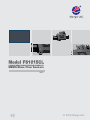
1
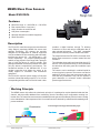
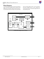
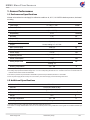
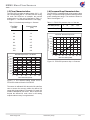
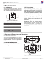
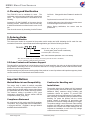
Model FS1015CL
SIARGO MEMS FLOW SENSING PRODUCTS
MEMS Mass Flow Sensors
VA.5
© 2014 Siargo Ltd.
MEMS Mass Flow Sensors
FS1015CL Series
User Manual
Document No.
Issue date:
Revision:
07-2014-S5 EN
2014.07
VA.5
Siargo Ltd.
2041 Mission College Boulevard
Suite 250
Santa Clara, CA 95054
USA
Tel: +1(408)969.0368
Email: [email protected]
© Copyright 2014 by Siargo Ltd.
Siargo Ltd. and its subsidiaries reserve the rights to change the specifications and/or
descriptions without prior notice. For further information and updates, please visit:
www.Siargo.com
MEMS Mass Flow Sensors
Model FS1015CL
Features
Mass flow range: 0 ~ 100 SLPM, 0 ~ 150 SLPM
Fast response time: 8 ms (max.)
Highly sensitive in small flow rate
Low power consumption
Specially designed for medical equipment
Small form factor
Description
The FS1015CL mass flow sensors are manufactured
using Siargo's proprietary MEMS flow sensor and
package technology. The sensors are specially
designed for the application of medical equipment
such as ventilators for flow monitoring and control with
two flow rate ranges of 0 ~ 100 SLPM and 0 ~ 150
SLPM, respectively. The compact package design
enables a large dynamic flow range with a pressure
drop of 1300 Pa (about 13 cmH2O) typically. This
package withstands a maximum pressure of 0.2 MPa
(29 psi) without compromising performance. The
mechanical interface is the standard ISO 15 mm
medical connection that allows the sensor to be
readily applied to ventilators and anesthesia
equipment.
The FS1015CL requires a power supply of 5 Vdc and
provides a linearized analog output of 0.5 to 4.5 Vdc
corresponding with flow rate from 0 to full scale. It also
2
provides a digital interface through I C allowing
customers to store and retrieve calibration data or
other relevant information. The AMP compatible
mechanical connector provides reliable connection.
The response time of the FS1015CL is less than 8 ms,
which allows customers to monitor instant flow rate
variations.
The calibration is generally performed with air at 20 °C
and 101.325 kPa pressure rating. It can nonetheless
be carried out with other gases and conditions upon
requests.
The sensors can be sterilized in medical liquids for
reuse or hygienic purposes. The sensors can also be
applied for various clean gas measurement with low
cost and easy installation. They can be used as a
good alternative to volumetric and/or differential
pressure type flow sensors.
Working Principle
The MEMS sensor chip utilizes the calorimetric principle. It is packaged on a plate installed inside the flow
channel, which provides additional flow conditioning from the boundary layer configuration resulting in a
laminar flow. The mass flow measurement is established as the gas carries heat away from the heater leading
to the redistribution of the temperature field. Accurate flow rate is obtained by calibration with standard gas at
preset conditions.
Flow direction
Time-averaged velocity profile boundary layer
Turbulent
Free stream
Laminar
Sensor
www.siargo.com
FS1015CL (VA.5)
1/8
MEMS Mass Flow Sensors
Block Diagram
The functional block diagram is shown in the following
figure. The critical component of the FS1015CL is the
MEMS sensor chip that is heavily framed in the figure.
It is powered by the sensor driving circuitry and sends
flow rate related voltage to ADC. The microcontroller
processes (amplifies, filters, etc) the voltage then
converts into flow rate. The flow rate signal is sent out
through analog format.
FS1015CL
Protection
Filtering
Voltage
Flow
Regulator
VCC
GND
EEPROM
SCL
MEMS
Sensor
Chip
Sensor
Driving
Circuitry
EEPROM
SDA
I/V
Converter
Vout
ADC
MCU
D/A
Functional block diagram of the FS1015CL.
www.siargo.com
FS1015CL (VA.5)
2/8
MEMS Mass Flow Sensors
1. Sensor Performance
1.1 Performance Specifications
All data unless otherwise noted apply for calibration conditions: air, 20 °C, 101.325 kPa absolute pressure, horizontal
mounting.
Model
FS1015
0 ~ 100; 0 ~ 150
Flow Range
> 100 : 1
Turn-down Ratio
Accuracy
SLPM
1
± (2.0 + 0.5 FS)
%
Repeatability
± 0.5
%Reading
Null Shift
± 30
mV
± 0.12
Output Shift
8 (max.)
Response Time
2
%/° C
ms
Linear, Analog 0.5 ~ 4.5 Vdc
Output
Max. Pressure Drop3
Max. Operation Pressure
Power Supply
4
Operating Current
Power Consumption
Analog Output Load
1300 Typ.
Pa
0.2
MPa
5 ± 1%
Vdc
< 10 (no output load)
mA
< 50
mW
Sourcing: 25
mA
Sinking: 15
Working Temperature
-10 ~ +55
°C
1 Denotes ±(2.0% Reading + 0.5% Full Scale). To obtain accurate flow measurement, let the sensor warm up 1 minute at power up.
2 The analog output provides linearized voltage of 0.5 ~ 4.5 Vdc corresponding with flow rate of 0 ~ full scale. There is an I2C interface that is for
customers to store and access sensor related data.
3 The maximum pressure drop is measured at 150 SLPM. For pressure drop at 100 SLPM, see section 1.4 for details.
4 One 5 Vdc power supply with an accuracy of ±1% is necessary. The minimum supply current must be larger than 10mA.
1.2 Additional Specifications
Mechanical Connection
1
Pins Out
Calibration Options
5 Pins, NS-TECH CD R-5
2
Dimension
Weight
Storage Temperature
Humidity
ISO - 15 mm
Air @ 20 ° C, 101.325 kPa
70.0 x 44.3 x 25.2
21.5
-20 ~ +65
mm
3
g
°C
< 95 %RH (No icing or condensation)
1 The 0.5m output connecting cable (part number: SN5-50) is shipped with the sensor.
2 The sensor is normally calibrated with air at 20 °C and 101.325 kPa pressure rating. Calibrations at other gases and conditions available upon
request.
www.siargo.com
FS1015CL (VA.5)
3/8
MEMS Mass Flow Sensors
1.3 Flow Characteristics
1.4 Pressure Drop Characteristics
The FS1015CL provides an analog output of 0.5 ~ 4.5
Vdc corresponding with 0 ~ full scale flow rate. Using
full scale 100 SLPM as an example, the nominal
analog output v.s. flow rate is illustrated in Table 1.1
and Figure 1.1. The data is obtained at 5.0 Vdc supply.
The FS1015CL is packaged with a low pressure drop
design. The pressure drop is measured throughout the
entire measurement range. The results are shown in
Table 1.2 and Figure 1.2.
Table 1.1: Nominal output voltage v.s. flow rate.
Nominal Voltage
(Vdc)
Flow Rate
(SLPM)
Flow Rate (SLPM)
0
50
100
150
Presure Drop (Pa)
0
200
600
1300
0
0.5
20
1.3
40
2.1
1400
60
2.9
1200
80
3.7
100
4.5
110
4.9
120
4.9
Pressure Drop (Pa)
FS1015CL Pressure Drop Curve
1000
800
600
400
200
0
Nominal Output Curve - 100 SLPM
Analog Output Voltage (V)
Table 1.2: FS1015CL pressure drop v.s. flow rate.
0
5.0
4.5
4.0
3.5
3.0
2.5
2.0
1.5
1.0
0.5
0.0
20
40
60
80
100
120
140
160
Mass Flow Rate (SLPM)
Figure 1.2: FS1015CL pressure drop v.s. flow rate.
0
20
40
60
80
100
120
Mass Flow Rate (SLPM)
Figure 1.1: The nominal analog output curve of
FS1015CL with the full scale of 100 SLPM.
The sensor is calibrated 10% above the full scale flow
rate to ensure the accuracy within the defined full
range during interpolation. For example, full scale 100
SLPM is calibrated till 110 SLPM. Hence at flow rate
beyond the defined full scale, there is still analog
output but the accuracy is not guaranteed.
www.siargo.com
FS1015CL (VA.5)
4/8
MEMS Mass Flow Sensors
2. Electrical Interface
2.1 Pin Definition
2.2 Pin Description
The FS1015CL provides a 5-pin interface. The output
connecting cable comes with the sensor and it is 0.5m
long. The sensor pin layout is shown in Figure 2.1 and
the cable color code is defined in Table 2.1.
VCC and GND: The FS1015CL requires a power
supply of 5±1% Vdc. The voltage is internally filtered
and regulated to power the circuit. The accuracy of the
power supply will influence the sensor output and the
±1% accuracy requirement should be met to ensure
the specified performance. The sensor consumes less
than 10 mA normally and the minimum supply current
must be larger than 10 mA.
Vout: The analog output pin provides 0.5 ~ 4.5
Vdc corresponding with the specified flow range
0 ~ full scale. Beyond this range, there is still
voltage reading, but the accuracy is not
guaranteed.
Figure 2.1: FS1015CL pin layout.
SDA and SCL : The I 2 C serial communication is
provided for storing and accessing sensorrelated information, such as calibration data.
SDA is the data pin and SCL is the clock pin. For
I 2 C communication protocol, please contact the
manufacturer.
Table 2.1: FS1015CL cable color code.
Pin #
Color
Definition
1
Blue
SDA
2
Green
Vout, Analog output
3
Red
VCC, Power supply
4
Black
GND, Ground
5
Yellow
SCL
3. Mechanical Dimensions and Mountings
3.1 Mechanical Interface
The FS1015CL provides standard ISO-15mm medical
connection and can be readily applied to ventilator and
anesthesia equipment. The inlet is a male interface
and the outlet is a female one. See Figure 3.1 for
details.
3.2 Mechanical Dimensions
3
The sensor has a total size of 70.0 X 44.3 X 25.2 mm ,
as shown in Figure 3.1.
Flow direction
Figure 3.1: The FS1015CL mechanical dimensions.
www.siargo.com
FS1015CL (VA.5)
5/8
MEMS Mass Flow Sensors
4. Cleaning and Sterilization
The FS1015CL can be sterilized for reuse. The
sterilization can be performed with liquid, gas and ultra
violet. The liquid sterilization is described as the
following.
for 30 min. Change with clean DI water for another 30
min.
Immerse the FLOW CHANNEL of the sensor into the
sterilizing solution. Make sure the entire sensor body
is within the solution but not the electronic cover for 30
min.
If sterilize with gas or ultra-violet, simply put the sensor
in the sterilizing environment for 30 min.
Dry the sensor in oven at 65 °C for 120 min.
Notice: During sterilization, the sensor must be
powered off.
Then rinse the sensor by immersing it under DI water
5. Ordering Guide
5.1 Sensor Selection
The sensor part number is composed of the product model number and suffix indicating the full scale flow rate,
mechanical connection, output format as well as the application gas. Refer the following for details.
FS1015CL
Gas (A - air; C - CO2; N - N2; O - O2; R - Ar;
for other gases, please contact manufacturer.)
Connection (ISO - ISO 15mm)
Max. scale Flow Rate* (Selectable: 100 or 150 SLPM)
* Max. flow rate number only, for example, 100 meaning full scale flow rate of 100 SLPM;
For CO2, selectable: 100SLPM (without 150 SLPM).
5.2 Order Contact and Customer Support
The sales offices are listed at the end of this document. For small quantities, the order can be placed either through
Siargo website: www.siargo.com or the convenient sales office. For large quantities, please contact the sales office,
distributors or sales representatives.
Siargo is making every effort to ensure the quality of the products. In case of questions and/or product supports, please
contact customer service listed at the end of the document.
Important Notices
Wetted Materials and Compatibility
The sensor body is made of medical compatible
plastics. The sensor chip comprises of silicon, silicon
nitride and silicon dioxide and the sensor chip surfaces
are passivated with silicon nitride and silicon dioxide.
The electronic sealing is provided by RTV (room
temperature vulcanizing) silicone sealant WR-704
composed of HOCH3 (SiO) nCH3H.
Compliance Statement
All components of this product are RoHS compliant.
The product fully complies with CE norm EN61000-61 through 61000-6-4, EN50081-2 through 50082-2
and EMC directive 89/336/EEC.
www.siargo.com
Cautions for Handling and
Installations
The product at the time of shipment is fully inspected
for product quality and meets all safety requirements.
Additional safety measures during handling and
installation should be applied. To prevent ESD
(electrostatic discharge) damage and /or degradation,
take customary and statutory ESD precautions when
handling. Do power the product with the correct
polarity, voltage & amperage. All precautions and
measures for electrical voltage handling must apply.
The product sealing is ensured to work under working
pressure of 0.2MPa and is leakage proof before the
shipment. But cautions and further leakage test are
important at installation as well since any leakage
could cause severe safety issue.
FS1015CL (VA.5)
6/8
MEMS Mass Flow Sensors
This product contains no user serviceable
components. Do not attempt to disassemble,
substitute parts or perform unauthorized modifications
to the product. Doing so will forfeit the terms of the
warranty and cause the liability to any damages
thereafter. It should only be serviced by authorized
personnel. Upon requests, Siargo will provide
necessary technical support and/or training of the
personnel.
Cautions for Product Applications
The product is designed for use with general purpose
gases such as air and nitrogen. It is advised that the
products are best used for non-explosive clean gases.
The sensors cannot be used for gas metrology of
fluoride or fluoride-containing gases. For updates of
the product certification information, please contact
the manufacturer. Use for other gases such as extreme
corrosive and toxic may cause the product
malfunctioning or even severe damages.
Don't expose the product's electronics other than the
inner flow channel to any liquids, the unit does not have
a water proof electronics. For medical sterilization
procedure, please consult the manufacturer. Don't flow
gas in conditions that can cause condensing water
vapor to be trapped inside the unit during operation as
the accuracy could be significantly influenced.
It is suggested to design your application so that
nominal flow rate is approximately 70% of the full scale
flow rating of the sensor. Don't use a sensor with a flow
range at the extreme cases, for instance, don't use a
150 SLPM sensor for a 1.5 SLPM application.
Warranty and Liability
(Effective January 2010)
Siargo warrants the products sold hereunder, properly
used and properly installed under normal
circumstances and service as described in this user
manual, shall be free from faulty materials or
www.siargo.com
workmanship for 180 days for OEM products, and 365
days for non-OEM products from the date of shipment.
This warranty period is inclusive of any statutory
warranty. Any repair or replacement serviced product
shall bear the same terms in this warranty.
Siargo makes no other warranty, express or implied
and assumes no liability for any special or incidental
damage or charges, including but not limited to any
damages or charges due to installation, dismantling,
reinstallation or any other consequential or indirect
damages of any kind. To the extent permitted by law,
the exclusive remedy of the user or purchaser, and the
limit of Siargo's liability for any and all losses, injuries or
damages concerning the products including claims
based on contract, negligence, tort, strictly liability or
otherwise shall be the return of products to Siargo, and
upon verification of Siargo to prove to be defective, at
its sole option, to refund, repair or replacement of the
products. No action, regardless of form, may be
brought against Siargo more than 365 days after a
cause of action has accrued. The products returned
under warranty to Siargo shall be at user or
purchaser's risk of loss, and will be returned, if at all, at
Siargo's risk of loss. Purchasers or users are deemed
to have accepted this limitation of warranty and liability,
which contains the complete and exclusive limited
warranty of Siargo, and it shall not be amended,
modified or its terms waived except by Siargo's sole
action.
This warranty is subject to the following exclusions:
(1) Products that have been altered, modified or have
been subject to unusual physical or electrical
circumstances indicated but not limited to those
stated in this document or any other actions which
cannot be deemed as proper use of the products;
(2) Siargo does not provide any warranty on finished
goods manufactured by others. Only the original
manufacturer's warranty applies;
(3) Products re-sold to the third parties.
FS1015CL (VA.5)
7/8
MEMS Mass Flow Sensors
Contact Information
Headquarters
Siargo Ltd.
2041 Mission College Blvd., Suite 250,
Santa Clara, California 95054 USA,
Phone: +01(408)969-0368
Email: [email protected]
Representative in US
Sentech Measurements, Inc.
P.O. Box 675265
6916 Circo Diegueno Court
Rancho Santa Fe, California 92067
Phone: +01-858-759-0613
Email: [email protected]
Representative in Japan
Marubeni Information Systems Co., Ltd.
Device Solutions Department
3-12-18 Shibuya,
Shibuya-ku, Tokyo 150-0002 Japan
Phone: +81-3-5778-8661
Representative in Europe
IDENTIC Stefanie Trojan
Roehlichstrasse 19
68723 Oftersheim Germany
Phone: +49-(0)6202-574198
Email: [email protected]
This document is intended for distribution to interested customer(s) only. Siargo and its subsidiaries reserve the
rights to change the specifications and/or descriptions without prior notice.
www.siargo.com
FS1015CL (VA.5)
8/8