Download Model MF5000
Transcript
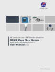
Model MF5000
SIARGO MEMS FLOW SENSOR PRODUCTS
MEMS Mass Flow Meter
VB.5
Siargo Ltd.
2041 Mi ssion Co llege Bl vd, St e 250
Sa nta Cl ara, CA 95054 US A
Tel:+1(408)969-0368
Em ail: Info@Si argo.com
Ht tp: //ww w. Si argo.com
© 2013 Siargo Ltd.
MF5000 Series User Manual (VB.5)
5. Warranty
Siargo warrants the products sold hereunder, properly used and properly installed under normal
circumstances and service as described in the user's manual, shall be free from faulty materials or
workmanship for 180 days for OEM products, and 365 days for non-OEM products from the date of
shipment. This warranty period is inclusive of any statutory warranty. Any repair or replacement serviced
product shall bear the same terms in this warranty.
Siargo makes no other warranty, expressed or implied and assumes no liability for any special or incidental
damage or charges, including but not limited to any damages or charges due to installation, dismantling,
reinstallation or any other consequential or indirect damages of any kind. To the extent permitted by Law,
the exclusive remedy of the user or purchaser, and the limit of Siargo's liability for any and all losses,
injuries or damages concerning the products including claims based on contract, negligence, tort, strictly
liability or otherwise shall be the return of products to Siargo, and upon verification by Siargo to prove to be
defective, at its sole option, to refund, repair or replacement of the products. No Action, regardless of form,
may be brought against Siargo more than 365 days after a cause of action has accrued. The products returned
under warranty to Siargo shall be at user or purchaser's risk of loss, and will be returned, if at all, at Siargo's
risk of loss. Purchasers or users are deemed to have accepted this limitation of warranty and liability, which
contains the complete and exclusive limited warranty of Siargo, and it shall not be amended, modified or its
terms waived except by Siargo's sole action.
This warranty is subject to the following exclusions:
a). Products that have been altered, modified or have been subject to unusual physical or electrical
circumstances indicated but not limited to those stated in the user's manual or any other actions
which cannot be deemed as proper use of the products
b). Siargo does not provide any warranty on finished goods manufactured by others. Only the original
manufacturer's warranty applies.
MF5000 Series User Manual (VB.5)
RESTRICTION ON USE
1. This meter is manufactured for general purpose industrial applications for flow
measurements. Do not alter any hardware and software of the product. Any
modifications might cause damage and unexpected events.
2. All practices for electronic device safety should apply.
3. Do not use this product in any environments where human safety may be at risk.
4. Only a qualified person from Siargo or a person who is accredited by Siargo can
perform troubleshooting services to the product, Siargo is otherwise not liable
for any consequences thereafter.
SAFETY PRECAUSION
6. Customer Service and Order information
Siargo Ltd. is making every effort to ensure the quality of the products. In case of questions, and or
product supports, please contact customer service at the address listed below. We will respond your
request in a timely fashion and will work with you toward your complete satisfaction.
Customer service and all orders should be addressed to
Siargo Ltd.
2041 Mission College Blvd, Suite 250
Santa Clara, CA 95054.
Tel: 01-(408)969-0368
Fax: 01-(408)777-8091
Email: [email protected]
For orders, please provide accurate and full post address. Siargo will not ship to P.O. Boxes or via a third
party.
For further information and updates, please visit www.Siargo.com.
www.Siargo.com
8
1. The product can be utilized to measure and/or monitor in-line mass flow rate of
any clean, dry and preferably constant concentration gases in industrial
applications. For other special gases or variable concentration gases, the product
may not function properly or even can be damaged. Please contact Siargo for
further information.
2. The operational environments of the product are illustrated in the section of
product specifications. If the product is used for other circumstances, the
product may not function properly or even can be damaged.
3. Operation, installation, storage, and maintenance of the product must strictly
follow the instructions illustrated in this user manual. Otherwise, unpredicted
damage and even injuries or other severe situations could be induced. All the
installation, storage, and maintenance of the product must be performed by
skilled workers. This user manual should be placed near the product for easy
access.
4. Before using the product, the user should read this user manual completely and
in details so that the user is well understand all the important instructions.
It is recommended that the product should be re‐ calibrated and serviced in
every two years or at a time of desire.
1
www.Siargo.com
MF5000 Series User Manual (VB.5)
MF5000 Series User Manual (VB.5)
3.5 4~20mA output
4~20mA Output(LOOP+,Purple )
The resistance loop should follow the relationship:
R L( max ) =450Ω
Contents
4~20mA GND(LOOP-,Colorless /Gray)
3.6 Pulse output
The meter supply pulse output in form of even square wave. The even square wave is composed of 3.3V
signal high and 0V signal low, and every pulse equal to 1SL.
RESTRICTION ON USE
SAFETY PRECAUSION
Contents
1 Overview
1.1 Siargo's MEMS Thermal Mass Flow Sensor Technology
1.2 Working Principle
1.3 Volume Flow vs. Mass Flow
2 Models and Selection
2.1 Product Selection
2.2 Physical Dimensions
2.3 Specifications
2.4 Flow Range
3 Installation
3.1 Description of Parts in Package
3.2 Installation and User Interface
3.3 Cautions for the Installation
3.4 RS485 Data Communication Protocol
3.5 4~20mA output
3.6 Pulse output
3.7 Automatic stored data
4 Safety and Maintenance
4.1 Wetted Materials and Compatibility
4.2 Safety Precautions
4.3 Maintenance
5 Warranty
6 Customer Service and Order information
1
1
2
3
3
3
3
4
4
4
4
5
5
5
5
6
6
7
7
7
7
7
7
7
8
8
3.7 Automatic stored data
The meter can automatically record mass flow rate, accumulated flow rate and time. To retrieve these data,
please contact manufacturer for the necessary user interface software. The data store interval can be
customized and please contact manufacturer for further information.
4.Safety and Maintenance
4.1 Wetted Materials and Compatibility
The meter body and pipe are made of 304 stainless steel. Sensors comprise of silicon, silicon nitride and
silicon dioxide and the sensor surfaces are passivated with silicon nitride and silicon dioxide. The
electronic sealing is provided by RTV (room temperature vulcanizing) silicone sealant WR-704 composed
of HOCH3(SiO)nCH3H.
4.2 Compliance Statement
All components of this product are RoHS compliant. The product fully complies with CE norm EN 610006-1 through 61000-6-4 , EN50081-2 through 50082-2 and EMC directive 89/336/EEC.
4.3 Safety Precautions
The product is designed for use with general purpose gases such as air and nitrogen. It is advised that the
products are best used for non-explosive clean gases. The meter cannot be used for gas metrology of
fluoride or fluoride containing gases. For updates of the product certification information, please contact
manufacturer or visit www.Siargo.com. Use for other gases such as extreme corrosive and toxic may cause
the product malfunctioning or even severe damages. The product sealing is ensured to work under working
pressure of 1. 5 MPa and is leakage proof before the shipment. But cautions and further leakage test are
important at installation as well since any leakage could cause severe safety issue. The power supply for
this product is 1 2 ~ 2 4 VDC, all precautions and measures for electrical voltage handling must apply.
Attention: any alternation and/or improper use of the product without the permission of the
manufacturer can cause unpredicted damages and even injuries or other severe situations. Siargo
Ltd. or any of its employees, subsidiaries shall not be hold and indemnified against such
consequences due to such circumstances via improper use of the product.
4.4 Maintenance
Attention: without prior permission of the manufacturer, please do not attempt to alter any parts of
the product as it may cause unrecoverable damages. If there are questions or doubts, please contact
manufacturer immediately before further actions. Please ensure the DC power is off before
disassembling the meter.
All maintenance of the meter should be done by trained and certified personnel by Siargo Ltd.
www.Siargo.com
2
7
www.Siargo.com
MF5000 Series User Manual (VB.5)
The installation must observe the following steps:
1. Make sure there are no any foreign materials in the pipeline.
2. Make sure there the seal gaskets are properly placed without interfering with the flow channel.
3. Connect the meter/sensor to the pipeline using proper tools to fasten the screws.
4. Initialization after power on, the display should show: Only for MF5000(e)
AUTO CHECKING
1) CRYSTAL
OK
2) ADC
OK
3) EEPROM
OK
4) RTC
OK
5. After initialization, the LCD will display Mass flow in the upper row and accumulated mass flow
(ACC.) in the lower row. Only for MF5000(e)
Note: because this flow meter is highly sensitive, only when the pipeline has absolutely no flow,
the display will be zero. To ensure the offset is working properly, make sure the pipeline has NO
flow.
6.Offset detection.
For certain models, when apply to gases different from the calibration gas, proper reset of the offset is
necessary for the meter to work. In this case,
Open upstream and downstream valves, make sure the gas (to be measured) is fully filled into the meter
and any other gases have been completely replaced. Wait for about 30 sec, close all of the valves,
initializing the meter using the Siargo Gas Meter User Interface software or the handheld device (provided
separately, please contact manufacturer for details), to reset the offset.
MF5000 Series User Manual (VB.5)
1. Overview
1.1 Siargo's MEMS Thermal Mass Flow Sensor Technology
Siargo's proprietary MF series MEMS mass flow sensor technology provides accurate in-line flow
measurement with the availability of customer-specified packages. The sensor is manufactured using
Siargo's unique MEMS process that ensures high reliability. The sensors can measure air flow as low as
0.01m/sec and as high as 75m/sec. Depending on the applications, the sensors can be used to measure mass
flow, volume flow or media flow speed. The specially designed circuit provides amplification as well as
small signal processing capability that yields a high accuracy.
Siargo's flow sensors utilize the same thermal mass flow technology using energy balance design. But
unlike the other MEMS flow sensing technologies, Siargo's flow sensors have multiple sensors integrated
on a single silicon chip. The surface of the chip is passivated by ceramic materials with high thermal
conductivity to ensure the sensor's sensitivity. It also enhances the reliability by avoiding the direct
contact among the sensors and the flow media. Also, Siargo's sensor design makes it easy to package the
sensor in a variety of ways, which significantly expands the applications of the technology.
1.2 Working Principle
a). Welding the pipe while the meter is installed is prohibited;
b). Any foreign materials in the pipeline after installation may cause irreversible damage;
c). Seal gaskets must not block flow channel otherwise accuracy cannot be maintained;
d). The meter should be properly grounded via the electrical connection;
e). After installation, severe force applied to the meter may cause damage;
f). Severe vibration or very strong magnetic field may cause malfunction;
Siargo's proprietary flow meter can measure gas flow in large pipes. The MEMS flow sensors are
integrated with a micro heater, local temperature sensors and environmental temperature sensor onto a
single chip. If no flow media passes through the MEMS sensor chip, a stable temperature field
(distribution) around the micro heater is maintained. When the flow media passes through the sensor chip,
the temperature field will be forced to change as the flow media will carry away the heat causing the
redistribution and variation of local temperature. Such a change of the local temperature will depend on
the media's mass as well as the media's flow speed. The sensors integrated on the silicon chip will then
measure such temperature redistribution, and the carefully designed signal process circuits and the
algorithm provided by the smart control software can then precisely measure the actual media mass flow
speed. This mass flow speed can then be translated into volume speed as well as accumulated volume
media consumption.
3.4 RS485 Data Communication Protocol
1.3 Volume Flow vs. Mass Flow
3.3 Cautions for the Installation
For purposes of computer control and networking, the RS485 is used for communication with the following
preferred settings:
Baud rate (Bits per second): 9600
Date bits:
8
Stop bits:
1
Parity:
None
Flow control:
None
Operation Mode :
i). Send 0x9d to the meter and return with 0x9d;
ii). Send 0x54 to the meter and return with 0x54;
The interval time between two bytes sent to the sensor must be longer than 5ms;
The sensor will be at Operation Mode at which the data from the meter will be sent via RS485 in an
interval of one second.
The data are in the following format:
S=vvvvv\nF=ffffff\nA=aaaaaaaa\n;\n
V=vvvvv Voltage code;
F=ffffff
Mass flow rate (Equal to fff.fff SLPM);
A=aaaaaaaaaaa Accumulated flow (Equal to aaaaaaaa.aaa SL).
User Mode:
i). Send 0x9d to the meter and return with 0x9d;
ii). Send 0x00 to the meter and return with 0x00;
The interval time between two bytes sent to the sensor must be longer than 5ms;
Then the sensor will be at User Mode at which the data will not be sent via RS485 by the meter.
www.Siargo.com
6
For the gas metrology using mechanical meters, the volume flow rate is adopted. The volume
rate nevertheless may not be a good indicator at industrial processing technology as the
processing gas quality depends vastly on the mass, not on the volume. In addition, the
volume of gas will change with different environment temperature and pressure. With the
MEMS thermal mass flow meter, it is possible to measure the "quality" (mass) of the gas
directly, and at real time. The mass flow rate will not depend on temperature and pressure.
Therefore an accurate measurement of the actual mass consumption becomes a reality. In
addition, the conversion of the mass rate to the volume rate is readily available by
referencing a standard condition such as 20 oC and 101.325 kPa.
3
www.Siargo.com
MF5000 Series User Manual (VB.5)
MF5000 Series User Manual (VB.5)
Communication
Mechanical Connection
Display
Calibration Air
2. Models and Selection
2.1 Product Selection
In addition to the models listed, we can also provide customized products that will be tailored to customers'
very needs. For further information, please contact manufacturer. The meters are made by referencing to:
ISO14511;
2.4 Flow Range
Flow Range*
MF
Gas (A-air; N-nitrogen; O-oxygen; R-argon; C-carbon dioxide; E-helium; Hhydrogen; for other gases, please contact Siargo)
Display* (D-with LCD display;N-without display)
Output(A-4~20mA;B-RS485;D-pulse,Options:B,AB,BD,ABD)
Maximum flow rate* (SLPM. e.g. 50 - 50 SLPM)
Connection (N-NPT)
Product series name
* There is flow rate number only for unit SLPM. If other unit is selected, there must be flow rate number with unit together.
** Only N can be selected for with Ex proof model, that means, there is no display for with Ex proof model.
2.2 Physical Dimensions
Model
DN
(mm)
Connection
(NPT-M)
L
H
W
d
c
Model
DN
(mm)
Connection
(NPT-F)
L
H
d
MF5003(e)
MF5006 (e)
MF5008(e)
MF5012(e)
MF5019(e)
3.0
6.0
8.0
12.0
19.0
1/8"
1/4"
3/8"
1/2"
3/4"
96
104
106
142
182.5
125
127
134
137
150
35
35
35
40
40
Ф3
Ф6
Ф8
Ф12
Ф19
36
36
50
50
70
MF5003(E)
MF5006(E)
MF5008(E)
MF5012(E)
MF5019(E)
3.0
6.0
8.0
12.0
19.0
1/8"
1/4"
3/8"
1/2"
3/4"
152
152
152
162
187
181
181
181
185
185
Ф3
Ф6
Ф8
Ф12
Ф19
98
H
H
66
150~15000
SCFM
SCMH
0.02~2
0.042~4.2
0.1~10
0.28~28
0.03~3
0.072~7.2
0.18~18
0.48~48
3.2 Installation and User Interface
The product at the time of shipment is fully inspected for product quality and meets all safety
requirements. Additional safety measures during the installation should be applied. This includes, but is
not limited to leakage verification procedures, standard EDS (electrostatic discharge) precautions, DC
voltage precautions, and heavy duty precautions. Other tasks such as calibration, part replacement, repair,
and maintenance must only be performed by trained personnel. Upon requests, manufacturer will provide
necessary technical support and/or training of the personnel.
Do not open the product cover or alter any part of the product. Any such actions will forfeit the terms of the
warranty and cause the liability to any damages thereafter.
两端
User Interface DB-9 (Male)
W
MF5000(e)
A
50
4-M4 深7
1 2 3 4 5
User Interface
A
38
24
A向
4-M5 深7
Meter Head
Display
MF5000(e)
MF5000(E)
60
2.3 Specifications
± (1.5+0.5FS)%;
-20~65 oC;
<1.5 MPa;
≤95%RH;
1 2 ~ 2 4 VDC, 50mA;
4
Flow Direction
MF5000(E)
6 7 8 9
L
c
www.Siargo.com
1/8"
1/4"
3/8"
1/2"
3/4"
SLPM
0.15~15
0.5~50
1.2~120
3~300
8~800
D
d
Accuracy
Working Temperature
Working Pressure
Humidity
Power supply
3.0
6.0
8.0
12.0
19.0
sccm
When unpacking your meter from the shipping container, three items should be found in the package:
a) The flow meter product
b) This user manual
c) Quality certificate and Warranty
Upon opening the package, the product physical integrity should be inspected to ensure no visual damage.
If any items are missing or any physical damages are observed, please contact the meter manufacturer
and/or the shipping agents to place a return/exchange or to identify the cause during the transit. If you are
uncertain of the installation or have any questions about the shipment, please also contact the
manufacturer or the shipping agents before further process.
Flow channel diameter(mm)
A向
MF5003
MF5006
MF5008
MF5012
MF5019
Connection
3.1 Description of Parts in Package
Proof (E-with Ex proof; e-without Ex proof)
L
DN
3. Installation
Minimum flow rate* ( 0 SLPM)
d
Model
*: Customer specified flow range and flow unit can be accommodated.
For CO 2 , flow range are 0.15~10, 0.5~40, 1.2~80, 3~200 and 8~600 SLPM.
Maximum working pressure (XXMPa. e.g. 06 - 0.6MPa)
D
两端
4~20mA/RS485/Pulse
NPT;
Mass flow, accumulated mass flow;
20 oC, 101.325 kPa ( other gases upon request);
1 4~20mA output
2 RS485(B)
3
4~20mA GND
Installation Fix Screw
4 Pulse output
(bottom)
5 Pulse GND
6 N.C.
7 RS485(A)
Flow Channel
8 Ground (Common)
9 Power supply(+)
MF5000(e)
Purple
Brown
Colorless
Yellow
White
Blue
Green
Black
Red
MF5000(E)
Purple
Brown
Gray
Yellow
White
Blue
Green
Black
Red
Notice: Upon open the package, if any component listed above is missing or any visible mechanical
damage is found, please contact supplier or distributors immediately. For additional assistance of
installation, please contact supplier or customer service.
5
www.Siargo.com
Pin Out
MF5000 Series User Manual (VB.5)
MF5000 Series User Manual (VB.5)
Communication
Mechanical Connection
Display
Calibration Air
2. Models and Selection
2.1 Product Selection
In addition to the models listed, we can also provide customized products that will be tailored to customers'
very needs. For further information, please contact manufacturer. The meters are made by referencing to:
ISO14511;
2.4 Flow Range
Flow Range*
MF
Gas (A-air; N-nitrogen; O-oxygen; R-argon; C-carbon dioxide; E-helium; Hhydrogen; for other gases, please contact Siargo)
Display* (D-with LCD display;N-without display)
Output(A-4~20mA;B-RS485;D-pulse,Options:B,AB,BD,ABD)
Maximum flow rate* (SLPM. e.g. 50 - 50 SLPM)
Connection (N-NPT)
Product series name
* There is flow rate number only for unit SLPM. If other unit is selected, there must be flow rate number with unit together.
** Only N can be selected for with Ex proof model, that means, there is no display for with Ex proof model.
2.2 Physical Dimensions
Model
DN
(mm)
Connection
(NPT-M)
L
H
W
d
c
Model
DN
(mm)
Connection
(NPT-F)
L
H
d
MF5003(e)
MF5006 (e)
MF5008(e)
MF5012(e)
MF5019(e)
3.0
6.0
8.0
12.0
19.0
1/8"
1/4"
3/8"
1/2"
3/4"
96
104
106
142
182.5
125
127
134
137
150
35
35
35
40
40
Ф3
Ф6
Ф8
Ф12
Ф19
36
36
50
50
70
MF5003(E)
MF5006(E)
MF5008(E)
MF5012(E)
MF5019(E)
3.0
6.0
8.0
12.0
19.0
1/8"
1/4"
3/8"
1/2"
3/4"
152
152
152
162
187
181
181
181
185
185
Ф3
Ф6
Ф8
Ф12
Ф19
98
H
H
66
150~15000
SCFM
SCMH
0.02~2
0.042~4.2
0.1~10
0.28~28
0.03~3
0.072~7.2
0.18~18
0.48~48
3.2 Installation and User Interface
The product at the time of shipment is fully inspected for product quality and meets all safety
requirements. Additional safety measures during the installation should be applied. This includes, but is
not limited to leakage verification procedures, standard EDS (electrostatic discharge) precautions, DC
voltage precautions, and heavy duty precautions. Other tasks such as calibration, part replacement, repair,
and maintenance must only be performed by trained personnel. Upon requests, manufacturer will provide
necessary technical support and/or training of the personnel.
Do not open the product cover or alter any part of the product. Any such actions will forfeit the terms of the
warranty and cause the liability to any damages thereafter.
两端
User Interface DB-9 (Male)
W
MF5000(e)
A
50
4-M4 深7
1 2 3 4 5
User Interface
A
38
24
A向
4-M5 深7
Meter Head
Display
MF5000(e)
MF5000(E)
60
2.3 Specifications
± (1.5+0.5FS)%;
-20~65 oC;
<1.5 MPa;
≤95%RH;
1 2 ~ 2 4 VDC, 50mA;
4
Flow Direction
MF5000(E)
6 7 8 9
L
c
www.Siargo.com
1/8"
1/4"
3/8"
1/2"
3/4"
SLPM
0.15~15
0.5~50
1.2~120
3~300
8~800
D
d
Accuracy
Working Temperature
Working Pressure
Humidity
Power supply
3.0
6.0
8.0
12.0
19.0
sccm
When unpacking your meter from the shipping container, three items should be found in the package:
a) The flow meter product
b) This user manual
c) Quality certificate and Warranty
Upon opening the package, the product physical integrity should be inspected to ensure no visual damage.
If any items are missing or any physical damages are observed, please contact the meter manufacturer
and/or the shipping agents to place a return/exchange or to identify the cause during the transit. If you are
uncertain of the installation or have any questions about the shipment, please also contact the
manufacturer or the shipping agents before further process.
Flow channel diameter(mm)
A向
MF5003
MF5006
MF5008
MF5012
MF5019
Connection
3.1 Description of Parts in Package
Proof (E-with Ex proof; e-without Ex proof)
L
DN
3. Installation
Minimum flow rate* ( 0 SLPM)
d
Model
*: Customer specified flow range and flow unit can be accommodated.
For CO 2 , flow range are 0.15~10, 0.5~40, 1.2~80, 3~200 and 8~600 SLPM.
Maximum working pressure (XXMPa. e.g. 06 - 0.6MPa)
D
两端
4~20mA/RS485/Pulse
NPT;
Mass flow, accumulated mass flow;
20 oC, 101.325 kPa ( other gases upon request);
1 4~20mA output
2 RS485(B)
3
4~20mA GND
Installation Fix Screw
4 Pulse output
(bottom)
5 Pulse GND
6 N.C.
7 RS485(A)
Flow Channel
8 Ground (Common)
9 Power supply(+)
MF5000(e)
Purple
Brown
Colorless
Yellow
White
Blue
Green
Black
Red
MF5000(E)
Purple
Brown
Gray
Yellow
White
Blue
Green
Black
Red
Notice: Upon open the package, if any component listed above is missing or any visible mechanical
damage is found, please contact supplier or distributors immediately. For additional assistance of
installation, please contact supplier or customer service.
5
www.Siargo.com
Pin Out
MF5000 Series User Manual (VB.5)
The installation must observe the following steps:
1. Make sure there are no any foreign materials in the pipeline.
2. Make sure there the seal gaskets are properly placed without interfering with the flow channel.
3. Connect the meter/sensor to the pipeline using proper tools to fasten the screws.
4. Initialization after power on, the display should show: Only for MF5000(e)
AUTO CHECKING
1) CRYSTAL
OK
2) ADC
OK
3) EEPROM
OK
4) RTC
OK
5. After initialization, the LCD will display Mass flow in the upper row and accumulated mass flow
(ACC.) in the lower row. Only for MF5000(e)
Note: because this flow meter is highly sensitive, only when the pipeline has absolutely no flow,
the display will be zero. To ensure the offset is working properly, make sure the pipeline has NO
flow.
6.Offset detection.
For certain models, when apply to gases different from the calibration gas, proper reset of the offset is
necessary for the meter to work. In this case,
Open upstream and downstream valves, make sure the gas (to be measured) is fully filled into the meter
and any other gases have been completely replaced. Wait for about 30 sec, close all of the valves,
initializing the meter using the Siargo Gas Meter User Interface software or the handheld device (provided
separately, please contact manufacturer for details), to reset the offset.
MF5000 Series User Manual (VB.5)
1. Overview
1.1 Siargo's MEMS Thermal Mass Flow Sensor Technology
Siargo's proprietary MF series MEMS mass flow sensor technology provides accurate in-line flow
measurement with the availability of customer-specified packages. The sensor is manufactured using
Siargo's unique MEMS process that ensures high reliability. The sensors can measure air flow as low as
0.01m/sec and as high as 75m/sec. Depending on the applications, the sensors can be used to measure mass
flow, volume flow or media flow speed. The specially designed circuit provides amplification as well as
small signal processing capability that yields a high accuracy.
Siargo's flow sensors utilize the same thermal mass flow technology using energy balance design. But
unlike the other MEMS flow sensing technologies, Siargo's flow sensors have multiple sensors integrated
on a single silicon chip. The surface of the chip is passivated by ceramic materials with high thermal
conductivity to ensure the sensor's sensitivity. It also enhances the reliability by avoiding the direct
contact among the sensors and the flow media. Also, Siargo's sensor design makes it easy to package the
sensor in a variety of ways, which significantly expands the applications of the technology.
1.2 Working Principle
a). Welding the pipe while the meter is installed is prohibited;
b). Any foreign materials in the pipeline after installation may cause irreversible damage;
c). Seal gaskets must not block flow channel otherwise accuracy cannot be maintained;
d). The meter should be properly grounded via the electrical connection;
e). After installation, severe force applied to the meter may cause damage;
f). Severe vibration or very strong magnetic field may cause malfunction;
Siargo's proprietary flow meter can measure gas flow in large pipes. The MEMS flow sensors are
integrated with a micro heater, local temperature sensors and environmental temperature sensor onto a
single chip. If no flow media passes through the MEMS sensor chip, a stable temperature field
(distribution) around the micro heater is maintained. When the flow media passes through the sensor chip,
the temperature field will be forced to change as the flow media will carry away the heat causing the
redistribution and variation of local temperature. Such a change of the local temperature will depend on
the media's mass as well as the media's flow speed. The sensors integrated on the silicon chip will then
measure such temperature redistribution, and the carefully designed signal process circuits and the
algorithm provided by the smart control software can then precisely measure the actual media mass flow
speed. This mass flow speed can then be translated into volume speed as well as accumulated volume
media consumption.
3.4 RS485 Data Communication Protocol
1.3 Volume Flow vs. Mass Flow
3.3 Cautions for the Installation
For purposes of computer control and networking, the RS485 is used for communication with the following
preferred settings:
Baud rate (Bits per second): 9600
Date bits:
8
Stop bits:
1
Parity:
None
Flow control:
None
Operation Mode :
i). Send 0x9d to the meter and return with 0x9d;
ii). Send 0x54 to the meter and return with 0x54;
The interval time between two bytes sent to the sensor must be longer than 5ms;
The sensor will be at Operation Mode at which the data from the meter will be sent via RS485 in an
interval of one second.
The data are in the following format:
S=vvvvv\nF=ffffff\nA=aaaaaaaa\n;\n
V=vvvvv Voltage code;
F=ffffff
Mass flow rate (Equal to fff.fff SLPM);
A=aaaaaaaaaaa Accumulated flow (Equal to aaaaaaaa.aaa SL).
User Mode:
i). Send 0x9d to the meter and return with 0x9d;
ii). Send 0x00 to the meter and return with 0x00;
The interval time between two bytes sent to the sensor must be longer than 5ms;
Then the sensor will be at User Mode at which the data will not be sent via RS485 by the meter.
www.Siargo.com
6
For the gas metrology using mechanical meters, the volume flow rate is adopted. The volume
rate nevertheless may not be a good indicator at industrial processing technology as the
processing gas quality depends vastly on the mass, not on the volume. In addition, the
volume of gas will change with different environment temperature and pressure. With the
MEMS thermal mass flow meter, it is possible to measure the "quality" (mass) of the gas
directly, and at real time. The mass flow rate will not depend on temperature and pressure.
Therefore an accurate measurement of the actual mass consumption becomes a reality. In
addition, the conversion of the mass rate to the volume rate is readily available by
referencing a standard condition such as 20 oC and 101.325 kPa.
3
www.Siargo.com
MF5000 Series User Manual (VB.5)
MF5000 Series User Manual (VB.5)
3.5 4~20mA output
4~20mA Output(LOOP+,Purple )
The resistance loop should follow the relationship:
R L( max ) =450Ω
Contents
4~20mA GND(LOOP-,Colorless /Gray)
3.6 Pulse output
The meter supply pulse output in form of even square wave. The even square wave is composed of 3.3V
signal high and 0V signal low, and every pulse equal to 1SL.
RESTRICTION ON USE
SAFETY PRECAUSION
Contents
1 Overview
1.1 Siargo's MEMS Thermal Mass Flow Sensor Technology
1.2 Working Principle
1.3 Volume Flow vs. Mass Flow
2 Models and Selection
2.1 Product Selection
2.2 Physical Dimensions
2.3 Specifications
2.4 Flow Range
3 Installation
3.1 Description of Parts in Package
3.2 Installation and User Interface
3.3 Cautions for the Installation
3.4 RS485 Data Communication Protocol
3.5 4~20mA output
3.6 Pulse output
3.7 Automatic stored data
4 Safety and Maintenance
4.1 Wetted Materials and Compatibility
4.2 Safety Precautions
4.3 Maintenance
5 Warranty
6 Customer Service and Order information
1
1
2
3
3
3
3
4
4
4
4
5
5
5
5
6
6
7
7
7
7
7
7
7
8
8
3.7 Automatic stored data
The meter can automatically record mass flow rate, accumulated flow rate and time. To retrieve these data,
please contact manufacturer for the necessary user interface software. The data store interval can be
customized and please contact manufacturer for further information.
4.Safety and Maintenance
4.1 Wetted Materials and Compatibility
The meter body and pipe are made of 304 stainless steel. Sensors comprise of silicon, silicon nitride and
silicon dioxide and the sensor surfaces are passivated with silicon nitride and silicon dioxide. The
electronic sealing is provided by RTV (room temperature vulcanizing) silicone sealant WR-704 composed
of HOCH3(SiO)nCH3H.
4.2 Compliance Statement
All components of this product are RoHS compliant. The product fully complies with CE norm EN 610006-1 through 61000-6-4 , EN50081-2 through 50082-2 and EMC directive 89/336/EEC.
4.3 Safety Precautions
The product is designed for use with general purpose gases such as air and nitrogen. It is advised that the
products are best used for non-explosive clean gases. The meter cannot be used for gas metrology of
fluoride or fluoride containing gases. For updates of the product certification information, please contact
manufacturer or visit www.Siargo.com. Use for other gases such as extreme corrosive and toxic may cause
the product malfunctioning or even severe damages. The product sealing is ensured to work under working
pressure of 1. 5 MPa and is leakage proof before the shipment. But cautions and further leakage test are
important at installation as well since any leakage could cause severe safety issue. The power supply for
this product is 1 2 ~ 2 4 VDC, all precautions and measures for electrical voltage handling must apply.
Attention: any alternation and/or improper use of the product without the permission of the
manufacturer can cause unpredicted damages and even injuries or other severe situations. Siargo
Ltd. or any of its employees, subsidiaries shall not be hold and indemnified against such
consequences due to such circumstances via improper use of the product.
4.4 Maintenance
Attention: without prior permission of the manufacturer, please do not attempt to alter any parts of
the product as it may cause unrecoverable damages. If there are questions or doubts, please contact
manufacturer immediately before further actions. Please ensure the DC power is off before
disassembling the meter.
All maintenance of the meter should be done by trained and certified personnel by Siargo Ltd.
www.Siargo.com
2
7
www.Siargo.com
MF5000 Series User Manual (VB.5)
5. Warranty
Siargo warrants the products sold hereunder, properly used and properly installed under normal
circumstances and service as described in the user's manual, shall be free from faulty materials or
workmanship for 180 days for OEM products, and 365 days for non-OEM products from the date of
shipment. This warranty period is inclusive of any statutory warranty. Any repair or replacement serviced
product shall bear the same terms in this warranty.
Siargo makes no other warranty, expressed or implied and assumes no liability for any special or incidental
damage or charges, including but not limited to any damages or charges due to installation, dismantling,
reinstallation or any other consequential or indirect damages of any kind. To the extent permitted by Law,
the exclusive remedy of the user or purchaser, and the limit of Siargo's liability for any and all losses,
injuries or damages concerning the products including claims based on contract, negligence, tort, strictly
liability or otherwise shall be the return of products to Siargo, and upon verification by Siargo to prove to be
defective, at its sole option, to refund, repair or replacement of the products. No Action, regardless of form,
may be brought against Siargo more than 365 days after a cause of action has accrued. The products returned
under warranty to Siargo shall be at user or purchaser's risk of loss, and will be returned, if at all, at Siargo's
risk of loss. Purchasers or users are deemed to have accepted this limitation of warranty and liability, which
contains the complete and exclusive limited warranty of Siargo, and it shall not be amended, modified or its
terms waived except by Siargo's sole action.
This warranty is subject to the following exclusions:
a). Products that have been altered, modified or have been subject to unusual physical or electrical
circumstances indicated but not limited to those stated in the user's manual or any other actions
which cannot be deemed as proper use of the products
b). Siargo does not provide any warranty on finished goods manufactured by others. Only the original
manufacturer's warranty applies.
MF5000 Series User Manual (VB.5)
RESTRICTION ON USE
1. This meter is manufactured for general purpose industrial applications for flow
measurements. Do not alter any hardware and software of the product. Any
modifications might cause damage and unexpected events.
2. All practices for electronic device safety should apply.
3. Do not use this product in any environments where human safety may be at risk.
4. Only a qualified person from Siargo or a person who is accredited by Siargo can
perform troubleshooting services to the product, Siargo is otherwise not liable
for any consequences thereafter.
SAFETY PRECAUSION
6. Customer Service and Order information
Siargo Ltd. is making every effort to ensure the quality of the products. In case of questions, and or
product supports, please contact customer service at the address listed below. We will respond your
request in a timely fashion and will work with you toward your complete satisfaction.
Customer service and all orders should be addressed to
Siargo Ltd.
2041 Mission College Blvd, Suite 250
Santa Clara, CA 95054.
Tel: 01-(408)969-0368
Fax: 01-(408)777-8091
Email: [email protected]
For orders, please provide accurate and full post address. Siargo will not ship to P.O. Boxes or via a third
party.
For further information and updates, please visit www.Siargo.com.
www.Siargo.com
8
1. The product can be utilized to measure and/or monitor in-line mass flow rate of
any clean, dry and preferably constant concentration gases in industrial
applications. For other special gases or variable concentration gases, the product
may not function properly or even can be damaged. Please contact Siargo for
further information.
2. The operational environments of the product are illustrated in the section of
product specifications. If the product is used for other circumstances, the
product may not function properly or even can be damaged.
3. Operation, installation, storage, and maintenance of the product must strictly
follow the instructions illustrated in this user manual. Otherwise, unpredicted
damage and even injuries or other severe situations could be induced. All the
installation, storage, and maintenance of the product must be performed by
skilled workers. This user manual should be placed near the product for easy
access.
4. Before using the product, the user should read this user manual completely and
in details so that the user is well understand all the important instructions.
It is recommended that the product should be re‐ calibrated and serviced in
every two years or at a time of desire.
1
www.Siargo.com
Model MF5000
SIARGO MEMS FLOW SENSOR PRODUCTS
MEMS Mass Flow Meter
VB.5
Siargo Ltd.
2041 Mi ssion Co llege Bl vd, St e 250
Sa nta Cl ara, CA 95054 US A
Tel:+1(408)969-0368
Em ail: Info@Si argo.com
Ht tp: //ww w. Si argo.com
© 2013 Siargo Ltd.


