1
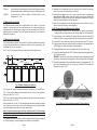
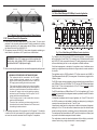
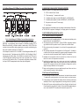
Thumb Screws Thumb Screws 1.4 Application Examples 1.4.1 Out-of-Band Managed 10/100Mbps Converter Application Power Supply #1 Power Supply #2 Fig. 5 5-Module Chassis with two Installed AC Power Supplies 3.3 DC Powered Chassis Site Preparation o Power source should be available within 5 ft. of the chassis. The over current protection for the connection with centralized DC shall be provided in the building installation and shall be a UL listed breaker rated at 20Amps, and installed per the National Electrical Code, ANSI/NFPA-70. o This equipment requires 36-60VDC/0.7 Amps power. Appropriate overloading protection should be provided on all DC power source outlets utilized. WARNING: Only a DC power source that complies with safety extra low voltage (SELV) requirements can be connected to the DC-input power supply. o When rack-mounting this equipment, the rack should be appropriately earth-grounded. o o o o WARNING REGARDING EARTHING GROUND: This equipment shall be connected to the DC supply system earthing electrode conductor or to a bonding jumper from an earthing terminal bar or bus to which the DC supply system earthing electrode is connected. This equipment shall be located in the same immediate area (such as adjacent cabinets) as any other equipment that has a connection between the earthed conductor of the same DC supply circuit and the earthing conductor, and also the point of earthing of the DC system. The DC system shall not be earthed elsewhere. The DC supply source is to be located within the same premises as this equipment. There shall be no switching or disconnecting devices in the earthed circuit conductor between the DC source and the earthing electrode conductor. o The operating temperature of this equipment is 0 to 50 degrees C. If installed in a closed or multi-unit rack assembly, the operating ambient temperature of the rack must not exceed the maximum rated 50 degrees C temperature. Page 8 Fig. 3 Out-of-Band Managed 10/100Mbps Converter Application Fig. 3 depicts an out-of-band managed 10/100 converter application. In this application, which is typical for a Central Office (CO) or a network core, a 5-Module chassis is loaded with 10/100 UTP to fiber converters that convert UTP cabling originating at a core switch to fiber and distributing the fiber in a star configuration to different customers. Out-of-band management is desirable in this application since it facilitates secure monitoring, configuration and trap notification of a large number of converter modules in the chassis. This application uses four 10/100 modules for UTP to fiber conversion and a SNMP or Telnet Management Module (MGT) for management. All modules are plugged into the 5-Module chassis. The 10/100 converter module is designed as a 4-port switch with two front-plane Ethernet ports (100Base-Fx fiber and 10/100Base-T/Tx UTP) and two 10/100 Ethernet backplane ports (A and B Ports). In this application, the A and B Ports are disabled to provide isolation between the modules. The MGT module features a 10Mbps Ethernet A Port. In this application, its A port is disabled and connectivity to the management network is performed via the MGT modules front-plane Ethernet port. It is important to emphasize that in this type of application, the A and B Ports of all of the 10/100 converters must be disabled to facilitate user data privacy by isolating the converters from each other and from the A and B Links. It should also be noted that in this configuration, in addition to data privacy infringement, enabling the A and B Links will cause a broadcast storm (since the modules create closed loops through the switch) or partitioning of some of the data paths by the switch. The management data flows between the MGT modules front-plane (out-of-band) and any secure and dedicated management network hardware. This configuration provides the network administrator with the ability to provide multicustomer service using a single chassis which is securely managed. Page 5