1
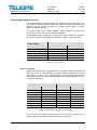
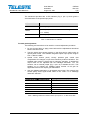
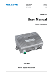
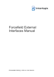
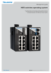
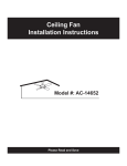
Broadband Cable Networks
User Manual
59300257
August 30, 2007
CXE800
Rev.003
1(8)
CXX Series
User Manual
Teleste Corporation
CXE800
Fibre Optic Receiver
Broadband Cable Networks
User Manual
59300257
August 30, 2007
CXE800
Rev.003
2(8)
Introduction
The CXE800 is a unidirectional, compact size fibre optic receiver. It is designed
for areas where cost-efficiency and easy installations are prime concerns.
The use of an integrated optical receiver eliminates time-consuming mounting
of connectors and fibre splicing inside the housing. The optical receiver
supports light wavelengths from 1290 nm to 1600 nm.
Alignment of this product is easy. The Optical Level Control (OLC) as well as
gain and slope adjustments use electrical controls that improve the reliability of
this fibre optic receiver. Plug-in accessories are not needed in normal oneoutput operation.
The distribution path, through the use of plug-in output modules, can be split
easily in the field within matter of minutes, and a full range of taps/splitters are
available.
WEEE Notice
This product complies with the relevant clauses of the European
Directive 2002/96/EC on Waste Electrical and Electronic Equipment
(WEEE). The unit must be recycled or discarded according to
applicable local and national regulations.
European Conformity
This equipment conforms to all applicable regulations and directives
of European Union which concern it and has gone through relevant
conformity assessment procedures.
User Manual
59300257
August 30, 2007
Broadband Cable Networks
CXE800
Rev.003
3(8)
Housing
8904047
1
2
3
4
Fig. 1. CXE800 Fibre Optic Receiver, 1) Optical fibre input port, 2) Ground,
3) RF output port2, 4) RF output port1
Installation
The fibre optic receiver can be installed either into a street cabinet or to a
sheltered outdoor environment. Note: Fibre adapter is not waterproof. The class
of enclosure is IP43. The amplifier should be installed in a vertical position so
that the external cable connectors are underneath. At least 100 mm of free
space should be left above the amplifier to ensure sufficient cooling air
circulation.
The cover of the housing is closed by a single bolt. There are no hinges. Open
cover is to be removed completely. When closing the cover use a PZD 2
screwdriver to tighten the bolt to a torque of 2.5...3.5 Nm. To ground the
amplifier housing connect at least 4 mm2 grounding wire (Cu) from a proper
earth to the grounding point.
Cable connections
Underneath the CXE800 fibre receiver there is one optical fibre input and one
RF output with F-female connector. Optionally a second RF output is available.
All coaxial outputs have a standard PG11 thread and they accept any KDC type
adapter or connector. Figure 2 illustrates the centre conductor.
8905010
Fig. 2. Centre conductor length
Broadband Cable Networks
User Manual
59300257
August 30, 2007
CXE800
Rev.003
4(8)
Powering
The locally powered CXE800 fibre optic receiver is connected to the main
voltage of 165…255 V AC via its own power cord. The power supply is double
shielded and does not require separate grounding. However, the amplifier
housing has to be grounded from the grounding point. The supply voltage fuse
(T3.15 A / 250 V / TR5) is located on the upper right corner of the amplifier,
beneath the shroud of the power supply unit.
Fibre installation
The CXE800 fibre optic receiver comes as standard with a bulkhead mounted
SC/APC adapter. Fibre installation is a critical procedure and it should be done
with carefulness. Incorrect handling of the fibre can result in damage and
degraded performance.
Warning: The SC/APC adapter is connected to the integrated fibre receiver
through a short length of fibre on the rear side of the bulkhead. To avoid
damage to the fibre, take care not to rotate the adapter when installing or
removing the fibre connector.
Cleaning fibre connectors
• For correct optical operation ensure that all optical connectors are cleaned
immediately before mating using a suitable optical connector cleaning kit.
• If a cleaning kit is not available, wipe the end of the connector using pure
isopropyl alcohol (99%) and a lint-free wipe. Dry it with filtered compressed
air. Wait until dry to insert connector into the adapter.
• When fibre optic connectors are unmated, the optical fibre end faces must
be protected from contamination using suitable dust caps. Contamination of
fibre end faces will reduce the performance of the optical fibre and could
ultimately cause failure of the system. Contamination could also damage the
fibre end faces when the connectors are mated.
User Manual
59300257
August 30, 2007
Broadband Cable Networks
CXE800
Rev.003
5(8)
Connectors and plug-in slots
8906026
1
4
-12
O
2
E
5
-8
-15
-4
mid
attenuator
optical power
3
58800016_002
TP 10 V/mW
OLC
OFF
output TP
-20 dB
8 dB
slope
OLC
ON
output module
flat
OUTPUT 2
10
9
OUTPUT 1
8
7
Fig. 3. CXE800 plug-in placement
1)
2)
3)
4)
5)
Integrated receiver
Indicator for optical input power
Optical power DC voltage test point
Midstage attenuator
Output test point, -20 dB directional coupler
6)
7)
8)
9)
10)
Output module
RF output port 1
RF output port 2
Slope selection
OLC mode jumper
OLC mode jumper (Fig. 3 pos. 10)
Slope selection (Fig. 3 pos. 9)
Off
Sloped 8 dB
On
Flat
Fig. 4. Jumper configurations.
6
User Manual
59300257
August 30, 2007
Broadband Cable Networks
CXE800
Rev.003
6(8)
Forward path / Optical receiver
The optical receiver is integrated within the CXE800 and will accept both 1310
and 1550 nm wavelength optical inputs. The optical receiver provides both LED
indicator and DC voltage test point for received optical power to quickly
determine status of the unit.
The output stage uses a GaAs MESFET output amplifier to improve RF
performance over the entire 47 to 862 MHz passband.
The distribution path, through the use of plug-in output modules, can be set up
for a variety of output configurations. Refer to the ‘Table 1. Output modules’.
Output module
Attenuation at 862 MHz
RF output port 1
RF output port 2
1.6 dB
1.1 dB
1.1 dB
4.0 dB
2.5 dB
12.5 dB
15.0 dB
20.6 dB
4.0 dB
8.3 dB
AC6112
AC6116
AC6119
AC6124
AC6128
Table 1. Output modules.
Optical input power
Optical input power can be measured from the optical power DC voltage test
point (Fig. 3 pos. 3). The test point DC voltage is directly proportional to optical
input power in mW e.g. 10 V corresponds to 1.0 mW average optical power.
Table below shows the correct measurements at the test point using a 1310 nm
or 1550 nm transmitter.
Operating wavelength 1310 nm
Operating wavelength 1550 nm
TP / V DC
Input / dBm
TP / V DC
Input / dBm
10.00
7.94
6.31
5.01
3.98
3.16
2.51
2.00
0
-1
-2
-3
-4
-5
-6
-7
11.2
8.87
7.05
5.60
4.45
3.53
2.80
2.23
0
-1
-2
-3
-4
-5
-6
-7
Table 2. CXE800 optical receiver, expected levels.
Do not connect any voltage to the test point or short circuit it to ground. Use a
voltage meter with an input resistance higher than 100 kohms.
Broadband Cable Networks
User Manual
59300257
August 30, 2007
CXE800
Rev.003
7(8)
The mainboard provides also a LED indicator (Fig. 3 pos. 2) which gives a
visual indication of the optical input power.
LED on CXE800
Condition
Yellow
Optical input power is below -7.0 dBm
Green
Red
Optical input power is within the nominal range
(-7.0…0 dBm)
Optical input power exceeds 0 dBm
Table 3. LED indicator on CXE800.
Forward path adjustment
The following are instructions to be used for a normal adjustment procedure.
1. Do not connect fibres or apply power before all the adjustments described
below have been made.
2. Test the optical input power present on the fibre service cable using an
optical power meter. The CXE800 integrated optical input power range is
from -7 dBm to 0 dBm.
3. Optical Level Control (OLC) circuitry provides gain control that
compensates for changes in input level caused by external variations. The
available gain reserve is factory-set for optimum operation. If needed the
output level can be adjusted with the midstage attenuator. You can
however, set an internal jumper (Fig. 3 pos. 10) to disable the OLC. This
enables you to operate the CXE800 optical receiver at full gain for
applications that do not require gain stabilization.
4. Use the midstage attenuator to get wanted output level. The network plan
should specify exact signal levels. Refer to the ‘Table 4 or 5. Midstage
attenuator selection’.
Output level (dBμV) without OLC
116
115
114
113
112
…
Midstage attenuator (dB)
0 dB
1 dB
2 dB
3 dB
4 dB
…
Table 4. Midstage attenuator selection when input power is -3 dBm at 4% OMI.
Broadband Cable Networks
User Manual
59300257
August 30, 2007
Output level (dBμV) with OLC
110
109
108
107
106
…
CXE800
Rev.003
8(8)
Midstage attenuator (dB)
0 dB
1 dB
2 dB
3 dB
4 dB
…
Table 5. Midstage attenuator selection when input power is between 0…-7 dBm at 4%
OMI.
5. Use the response mode jumper (Fig. 3 pos. 9) to select the midstage slope.
Available options are “flat” or “8 dB sloped”.
6. Apply the power.
7. Connect the fibre connector to the bulkhead adapter.