1
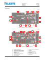
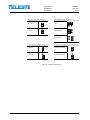
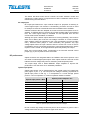
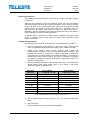
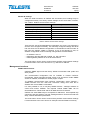
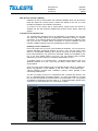
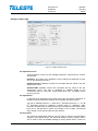
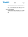
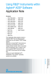
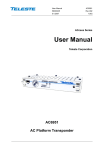
User Manual
CXE85X
59300464
Rev.005
9.12.2013
1(44)
CXX Series
User Manual
Teleste Corporation
CXE851 / CXE852
Single / Dual optical receiver
with Ethernet management
User Manual
CXE85X
59300464
Rev.005
9.12.2013
2(44)
Contents
Introduction ........................................................................................................ 3
CXE85x generations ............................................................................................ 3
Installation .......................................................................................................... 4
Housing ................................................................................................................ 4
Powering .............................................................................................................. 5
Interfaces ............................................................................................................. 5
Fibre installation................................................................................................... 6
Front panel ........................................................................................................... 7
Features .............................................................................................................. 9
Local user interface ............................................................................................. 9
RF performance ................................................................................................. 10
Establishing connection ..................................................................................... 13
Management interfaces ..................................................................................... 14
Viewer pages (SNMP interface) ...................................................................... 17
Status viewer page ............................................................................................ 18
Settings viewer page ......................................................................................... 19
Communication viewer page ............................................................................. 21
NTP viewer page ............................................................................................... 23
Alarm log viewer page ....................................................................................... 24
Monitoring viewer page ..................................................................................... 25
Properties viewer page ...................................................................................... 28
Web user interface........................................................................................... 29
Home WebUI page ............................................................................................ 29
Monitoring WebUI page ..................................................................................... 30
Log WebUI page ................................................................................................ 32
Communication WebUI page ............................................................................. 33
SNMP WebUI page ........................................................................................... 34
Time WebUI page .............................................................................................. 36
Properties WebUI page ..................................................................................... 37
Maintenace WebUI page ................................................................................... 38
CLI commands ................................................................................................. 40
Legal declarations ........................................................................................... 43
User Manual
CXE85X
59300464
Rev.005
9.12.2013
3(44)
Introduction
CXE851 is a single input fibre optical receiver and CXE852 is a dual input fibre
optical receiver. Both receivers can be monitored and controlled through
standard Ethernet interface using WebUI, SNMP and CLI interfaces. They are
designed for cases which don't need optical transmitter and only a downstream
signal is required.
CXE85x optical receivers feature an 1006 MHz bandwidth and integrated
optical receiver(s). The use of integrated optical receiver(s) eliminates timeconsuming mounting of connectors and fibre splicing inside the housing. The
optical receiver(s) supports light wavelengths from 1290 nm to 1600 nm.
Alignment of CXE85x is easy. The Optical Level Control (OLC) as well as gain
and slope adjustments use electrical controls that improve reliability. Installation
can be carried out using basic tools without any software. Local or remote
configuration using PC software is also possible, allowing fine-tuning the
product.
The RF output port is equipped with DC voltage connection controlled by
processor. It can be used to control external equipment, for example Ethernet
switch powering.
CXE852 and CXE851 differ only in one respect: CXE852 is equipped with two
optical receivers and provides either manual or automatic switchover between
the two inputs.
CXE85x generations
There are two CXE85x generations with some differences in hardware and/or
software functionality:
st
1 generation CXE85x:
•
Manufactured until Q2/2013
•
Two slope adjustment values: 0 dB / 10 dB
•
Gain adjustment range 0…-15 dB (HW mode) / 0…-20 dB (SW mode)
nd
2 generation CXE85x:
•
Manufacturing started Q2/2013
•
Three slope adjustment values: Flat / Middle / High (0 dB / 7 dB / 9 dB)
•
Gain adjustment range 0…-31 dB and additional "attenuator range"
selection jumper.
User Manual
CXE85X
59300464
Rev.005
9.12.2013
4(44)
Installation
Housing
8912081
1
2
3
4
5
Figure 1. CXE85x Single / dual fibre optical receiver, 1) Optical fibre input port, 2)
Ethernet port, 3) Ground, 4) Optical fibre input port 2 (CXE852), 5) RF output port
The CXE85x can be installed either into a street cabinet or to a sheltered
outdoor environment. Note: The fibre adapter and the Ethernet port are not
waterproof. The CXE85x should be installed in a vertical position so that the
connectors are underneath. At least 100 mm of free space should be left above
the amplifier to ensure sufficient cooling air circulation. The housing should be
2
with at least 4 mm grounding wire (Cu) from a proper earth to the grounding
point.
User Manual
CXE85X
59300464
Rev.005
9.12.2013
5(44)
The lid of the housing is secured by a single bolt. There are no hinges. Open lid
should be removed completely. Using 4 mm Allen key, the retaining bolt is
fasten with a tightening torque of 2.5...3.5 Nm. Before closing the lid ensure
that:
-
nothing is trapped between the lid and the case
-
all case gaskets are in their correct positions
-
lid seats evenly on the rubber gasket
The class of enclosure is IP31 when correctly installed and tightened.
Powering
The locally powered CXE85x fibre optic receiver is connected to the main
voltage of 165…255 V AC via its own power cord. The power supply is double
shielded and does not require separate grounding. However, the amplifier
housing has to be grounded from the grounding point. The supply voltage fuse
is located on the upper right corner of the amplifier, beneath the shroud of the
power supply unit. To replace the fuse:
-
disconnect the power before removing the shroud of the PSU
-
identify and clear the condition that caused the original fuse failure
-
replace the fuse, the fuse is of the type T3.15 A / 250 V / TR5
-
refit the shroud
Interfaces
Underneath the CXE85x there is one/two optical fibre input(s) and one RF
output. The RF output has a standard PG11 thread and accepts any KDC type
adapter or connector. Figure 2 illustrates the centre conductor. RF output port is
factory installed with F female adapter.
8910036
Figure 2. Centre conductor length
The CXE85x can be connected to Local Area Network (LAN) via a standard
(RJ45) 10/100Base-T Ethernet connection (Figure 1 pos. 2).
User Manual
CXE85X
59300464
Rev.005
9.12.2013
6(44)
Fibre installation
The CXE85x comes as standard with a bulkhead mounted SC/APC adapters.
Fibre installation is a critical procedure and it should be done with care.
Incorrect handling of the fibre can result in damage and degraded performance.
Warning: The SC/APC adapter is connected to the integrated fibre receiver
through a short length of fibre on the rear side of the bulkhead. To avoid
damage to the fibre, take care not to rotate the adapter when installing or
removing the fibre connector.
Cleaning fibre connectors
• For correct optical operation ensure that all optical connectors are cleaned
immediately before mating using a suitable optical connector cleaning kit.
• If a cleaning kit is not available, wipe the end of the connector using pure
isopropyl alcohol (99%) and a lint-free wipe. Dry it with filtered compressed
air. Wait until dry to insert connector into the adapter.
• When fibre optic connectors are unmated, the optical fibre end faces must
be protected from contamination using suitable dust caps. Contamination of
fibre end faces will reduce the performance of the optical fibre and could
ultimately cause failure of the system. Contamination could also damage the
fibre end faces when the connectors are mated.
User Manual
CXE85X
59300464
Rev.005
9.12.2013
7(44)
Front panel
8913048
1
8
7
5
3
9
15
10
12
6
13
Figure 3. CXE851 front panel (2
nd
11
generation)
8913055
1
2
5
6
7
8
3
9
4
15
10
12
13
14
11
Figure 4. CXE852 front panel (2
1)
2)
3)
4)
5)
6)
7)
8)
Integrated optical receiver 1
Integrated optical receiver 2 (CXE852)
Optical power DC voltage test point 1
Optical power DC voltage test point 2
(CXE852)
Mid stage attenuator
Mid stage attenuator range jumper
Slope selection jumper
OLC mode jumper
nd
9)
10)
11)
12)
13)
14)
15)
generation)
Output test point, -20 dB directional
coupler
RF output
External control jumper
Status LED
Optical input power 1 LED
Optical input power 2 LED
Reset button
User Manual
CXE85X
59300464
Rev.005
9.12.2013
8(44)
Attenuator range (Fig. 3/4 pos. 6)
Slope selection (Fig. 3/4 pos. 7)
16-31 dB
Flat
0-15 dB
Middle sloped
High sloped
OLC mode jumper (Fig. 3/4 pos. 8 )
External control jumper (Fig. 3/4 pos. 11)
OLC ON
External control ON
OLC OFF
External control OFF
Figure 5. Jumper configurations
User Manual
CXE85X
59300464
Rev.005
9.12.2013
9(44)
Features
Local user interface
The local user interface consists of two/three status LEDs for optical input
power and general status, a reset button, a rotary switch for midstage gain
setting, three jumpers for setting the output slope, gain adjustment range and
controlling the OLC and one jumper controlling the DC voltage connection at the
RF output port.
LEDs
The optical input power LED is red when the optical input power has a major
alarm (i.e. is outside major alarm limits), yellow when it has a minor alarm (i.e.
between major alarm limits but outside minor alarm limits), otherwise green.
The status LED is red when there is at least one major alarm related to RF
output power, temperature, local power supply or internal error. It is yellow
when there are no major alarms but at least one minor alarm. Otherwise it is
green.
The status LED blinks when the RF controls are under software control and
changing the rotary switch or jumpers has no effect. Hardware control can be
restored using the reset button.
Reset button
The reset button can be used to restore RF controls to hardware control, to
reset communication settings back to factory values or to reset all settings back
to factory values.
Button pressed
Status LED
Action when released
<1 s
1...5 s
5...10 s
10...15 s
>15 s
dark
green
yellow
red
dark
RF controls return to hardware control
Communication settings are reset
All settings are reset to factory values
-
Table 1. Reset button functions
When the button is released while the status led is green/yellow/red, the status
LED blinks briefly in the same colour to indicate successful operation.
The communication settings reset enables DHCP and sets SNMP communities
to read:public and write:private. This can be used to e.g. restore communication
with a device whose IP address is unknown.
RF controls
The rotary switch can be used to attenuate output level in 1 dB steps between
0...15 dB. 2nd generation devices feature two attenuation ranges (0…15 dB or
16…31 dB) to adjust the output level. The attenuator ranges are selected using
the attenuator range selection jumper.
OLC can be disabled with a jumper for high output level applications. When
disabled, the input attenuator is set equivalent to -4 dBm input power.
Output slope can be selected between flat, middle or high with a jumper. The
nd
middle option is available only with 2 generation devices.
User Manual
CXE85X
59300464
Rev.005
9.12.2013
10(44)
The status led blinks when the RF controls are under software control and
changing the rotary switch or jumpers has no effect. Hardware control can be
restored using the reset button.
RF output port
RF output port features an “open collector output” for purposes of alarming or
control signal output. The function is controlled by processor and can be used
for example to reset an external Ethernet switch installed next to CXE85x.
CXE85x measures the time elapsed since last received unicast packet to its IP
address. If CXE85x does not receive any unicast packets within user-specified
time, the control signal output is activated for user-specified time and the
unicast receive time calculation is restarted.
Although the open collector output allows a lot of wiring flexibility, care must be
taken not to destroy the circuit via over-voltage, transients or current overload.
Open collector output is specified for max. 100 mA switching current (30 VDC
max.). Inductive loads (relays or other solenoids) can generate very high
voltage spikes when the open collector switch is turned off. If such a load is
unavoidable, the use of transient suppression components parallel to the load is
required. This is critical, as a single transient pulse may destroy the output.
Note: If the control signal output functionality is not used the external control
jumper (Fig. 3 pos.10) must be set to OFF state
RF performance
Optical receivers are integrated within the CXE85x and will accept both 1310
and 1550 nm wavelength optical inputs. Each optical receiver have both a LED
indicator and DC voltage test point for measuring received optical power.
The output stage uses a GaAs MESFET output amplifier to improve RF
performance over the entire 47 to 1006 MHz passband.
Optical input power
Optical input power can be measured from the optical power DC voltage test
point (Figure 4 pos. 3, 4). The test point DC voltage is directly proportional to
optical input power in mW e.g. 1 V corresponds to 1.0 mW average optical
power in 1310 nm operation. In 1550 nm operation subtract 0.5 dBm.
Optical input power / dBm
+2
+1
0
-1
-2
-3
-4
-5
-6
-7
Optical power testpoint / VDC
1310 nm
1.58
1.26
1.00
0.79
0.63
0.50
0.40
0.32
0.25
0.20
1550 nm
1.78
1.41
1.12
0.89
0.71
0.56
0.45
0.35
0.28
0.22
Table 2. Optical input power DC test point voltages
Do not connect any voltage to the test point or short circuit it to ground. Use a
voltage meter with an input resistance higher than 100 kΩ.
User Manual
CXE85X
59300464
Rev.005
9.12.2013
11(44)
Optical input selection
The CXE852 optical input selection can be set to 3 modes: Automatic, Manual
1, Manual 2.
When the input selection is set to the “Automatic” mode, the node automatically
selects the optical input according to signal conditions. If the optical input power
at the main input is out of major alarm limits, input 2 will be selected provided
that its optical input power is inside major alarm limit + deadband. Input 1 is
selected when its optical input power is above low major alarm limit +
deadband. This fully automatic input selection between the two inputs offers a
useful redundancy mode for critical applications.
In “Manual: RX #1” mode input 1 is always used, regardless of the optical input
power. In “Manual: RX #2” mode input 2 is always used, regardless of the
optical input power.
Forward path adjustment
The following are instructions to be used for a normal adjustment procedure.
1. Test the optical input power present on the fibre using an optical power
meter. The CXE85x optical input power range is from -7 dBm to +2 dBm.
2. Optical Level Control (OLC) circuitry provides gain control that
compensates for changes in input level caused by external variations. The
available gain reserve is factory-set for optimum operation. If needed the
output level can be adjusted with the mid stage attenuator. It is possible to
disable the OLC with a jumper (Figure 4 pos. 8) or via software. This makes
it possible to operate the CXE85x at full gain for applications that do not
require gain stabilization.
3. Use the mid stage attenuator to get wanted output level. The network plan
should specify exact signal levels. Refer to the "Table 3. Mid stage
attenuator selection and output level".
4.
Mid stage
attenuator
0 dB
1 dB
2 dB
3 dB
…
15 dB
16 dB
…
31 dB
OLC enabled
-7...+2 dBm @ 4 % OMI
115 dBµV
114 dBµV
113 dBµV
112 dBµV
…
100 dBµV
99 dBµV
…
84 dBµV
OLC disabled
-4 dBm @ 4 % OMI
116 dBµV
115 dBµV
114 dBµV
113 dBµV
…
101 dBµV
100 dBµV
…
85 dBµV
Table 3. Mid stage attenuator selection and output level
5. Use the slope selection jumper (Figure 4 pos. 7) to select the mid stage
slope.
6. Apply the power.
7. Connect the fibre connector to the bulkhead adapter.
User Manual
CXE85X
59300464
Rev.005
9.12.2013
12(44)
Forward path adjustment via software
The mid stage gain, OLC enabling and slope setting can be taken into software
control. When software control is enabled, the rotary switch and jumpers have
no effect. Hardware control can be restored with reset button or via software.
There are two software control modes: manual and OMI-based. The difference
between these is in how gain is controlled. In manual mode the gain can be set
as via hardware, -15...0 dB in 1 dB steps. In newer software releases this range
st
nd
is -20…0 dB for 1 generation devices, and -31…0 dB for 2 generation
devices. In OMI-based mode the CXE85x calculates the correct gain based on
the user-specified transmitter OMI-% and target output level.
RF output power
CXE85x measures its RF output with a wideband RF detector. The result is
displayed in (approximate) dBm reading, but due to the detector frequency
response curve and calibration issues, no accuracy specification is given. The
factory default setting for the alarms is only low minor alarm enabled at -15
dBm. All alarm limits and enables can be edited by the user, and there is a
shortcut button in the UI for setting the alarm limits to ±3 and ±6 dB from the
measured value.
User Manual
CXE85X
59300464
Rev.005
9.12.2013
13(44)
Establishing connection
Ethernet port
The Ethernet port of CXE85x supports both 10 and 100 Mbps half and full
duplex standard Ethernet connection. The port has a Auto-MDI/MDI-X feature,
thus the connection between CXE85x's RJ-45 port and a PC or Ethernet switch
can be made with either straight or crossed cable.
There are two LEDs in the RJ-45 connector:
− Green led: Link OK, blinking means activity
− Yellow led: Speed 100 Mbps
DHCP / AutoIP
CXE85x can be configured to obtain its IP address automatically with its built-in
DHCP client. Another possibility is to manually set the IP settings.
The DHCP client makes it possible to install the unit without a PC, without
making any communication settings. Only plugging in the Ethernet cable,
checking that the green link led lights up and writing down the MAC address is
needed. The MAC address is visible on the sticker next to CXE85x's Ethernet
port and can later be used to identify the unit and assign it correct IP address
via the DHCP server configuration.
The DHCP client with AutoIP feature is enabled by default and has essentially
the same functionality than in e.g. Windows PC. First the DHCP client tries to
connect to a DHCP server to obtain an IP address, netmask and gateway
settings. If CXE85x is not able to find a DHCP server within ~1 minute, it uses
the AutoIP feature: sets netmask to 255.255.0.0 and finds the first free IP
address in the AutoIP address space, usually 169.254.1.1.
A Windows XP / Vista / 7 / 8 PC in a typical configuration (DHCP enabled) uses
the same AutoIP range it if cannot find a DHCP server. Thus the initial
configuration of a CXE85x is simple: established communication link by simply
connecting the PC and CXE85x together with a straight or crossed Ethernet
cable.
Depending on the PC settings, it may require up to minute or two for the DHCP
client to fail and go to AutoIP mode. Some systems may in certain situations
even require that the Local Area Connection is briefly disabled and enabled
again via Control Panel.
Initial connection to CXE85x can be naturally established also by manually
configuring the PC's IP address settings so that it belongs to the AutoIP subnet,
i.e. IP 169.254.x.y and netmask 255.255.0.0.
Note that the AutoIP subnet is not routable, thus it requires a direct cable
connection between PC and CXE85x.
User Manual
CXE85X
59300464
Rev.005
9.12.2013
14(44)
Manual IP settings
When the initial connection to CXE85x has succeeded, its IP settings may be
configured manually. The factory default settings are the same than in AutoIP,
see "Table 4. Default communication settings".
Parameter
IP address (static)
Netmask (static)
Gateway (static)
DHCP & AutoIP
SNMP read community
SNMP write community
Default setting
169.254.1.1
255.255.0.0
0.0.0.0
Enabled
public
private
Table 4. Default communication settings
There are two sets of IP/mask/gateway parameters: the ones is use (read-only)
and the ones configured manually. The manually configured settings are taken
into use when the 'IP address configuration' is commanded to manual mode. At
this point the settings' validity is checked. If any of the following is true, IP
address configuration mode is internally changed back to DHCP/AutoIP:
− IP address is 0.0.0.0
− Netmask is 255.255.255.255 or illegal, e.g. 255.128.255.0
− Default gateway address is not in the same subnet
The reset button can be used to restore factory default communication settings
if communication to the unit is lost due to e.g. unknown IP address.
Management interfaces
SNMP communication
CXE85x's SNMP agent uses the factory default communities read: public and
write: private.
The recommended configuration tool for CXE85x is Teleste CATVisor
Commander. Viewer package DUS100 version 4.23 and above contain SNMP
viewer for CXE85x, for detail see "Viewer pages" chapter.
To establish communication with CATVisor Commander, select "Remote" /
"SNMP Element" from the "Add new connection" dialog, then enter the IP
address and correct SNMP communities.
It is also possible to use a 3rd party SNMP browser / manager software to
control and monitor CXE85x. The required Teleste SNMP MIBs can be
downloaded from Teleste Club and SCTE MIBs from SCTE website.
CXE85x can send SNMP traps to 2 separate IP addresses, with separate trap
community and port settings. The trap sending behaviour can be fine-tuned with
delay, interval and lifetime parameters.
The reset button can be used to restore factory default communication settings
if communication to the unit is lost to for example unknown SNMP community.
User Manual
CXE85X
59300464
Rev.005
9.12.2013
15(44)
Web browser Interface (WebUI)
CXE85x has also a web browser user interface (WebUI) which can be used to
read and adjust RF controls and to monitor the status of the unit. It is also
possible to update the unit software via WebUI.
To connect to the device with a web browser, simply enter the device IP
address into the web browser’s address bar and the unit’s “Home” page will
appear.
Command Line Interface (CLI)
The command line interface (CLI) is an alternative to the WebUI. The CLI lets
you view and modify status and configuration information through a network
connection. If you already deployed the network and know the IP address of the
unit, you can use a remote Telnet connection to view the CXE85x over the
network. CXE85x supports up to four simultaneous Telnet connections.
Enabling Telnet in Windows 7
First of all, make sure you have Telnet enabled in Windows. You can do this by
opening Windows Command window by typing ‘cmd’ into the Start menu
search. In Commander windows, type ‘Telnet’. If you get a Telnet prompt, you
have Telnet enabled. If you get an error message, Telnet is not enabled in your
PC. If you have admin rights to your PC, you can enable Telnet yourself.
Otherwise you must contact your computer administrator to do it.
To enable Telnet, go to Control Panel - ‘Programs and Features’ and ‘Turn
Windows features on or off’. From the list, select ‘Telnet client’. Then close
Control Panel.
Once you have Telnet enabled, type to command window ‘telnet <ip_address>’,
where <ip_address> is the address of the unit. After a successful login, ,
"HELLO [ipaddr]" appears with "CXE852>" prompt, where [ipaddr] is the
connecting machine's IP.
You are now ready to enter CLI commands at the command line prompt. The
CLI is a straightforward command interface. You type commands on a single
line, and the commands are executed when you press Enter. You can get a list
of available commands by typing in ‘help’ or ‘?’. A brief explanation follows each
command. For more detail see "CLI commands" chapter.
User Manual
CXE85X
59300464
Rev.005
9.12.2013
16(44)
Monitored parameters
The CXE85x monitored parameters are described in the table below. SNMP
traps, if enabled, are sent to user specified IP addresses.
The affected LED and factory default severity settings are presented next to
each parameter. All alarm severities (Major / Minor / Notification / Disabled) and
alarm limits can be fully configured by the user. See the "Monitoring" chapter for
more details.
Note that some alarm limits (e.g. RF output power) are factory configured so
that alarms will only appear when hardware specifications are exceeded. The
alarm limits should be reconfigured to match network parameters if more
precise monitoring is needed.
LED
Default
severity
Optical input power level is above high limit.
Optical
Major & Minor
Optical input power level is below low limit.
Optical
Major & Minor
Temperature high Internal temperature is above high limit.
Temperature low Internal temperature is below low limit.
Status
Status
Major & Minor
Major & Minor
RF output power
high
RF output power is above high limit.
Status
-
RF output power
low
RF output power is below low limit.
Status
Minor
Status
Major
Status
Major
Alarm text
Description
Optical input
power high
Optical input
power low
Power supply
failure
Internal error
Internal +12 V voltage is out of range. If resetting
the unit doesn't help, it should be sent to service.
The unit has an internal error. If resetting the unit
doesn't help, it should be sent to service.
Application
started
Unit was reset or rebooted during last minute.
-
Minor
Settings changed
Unit's settings have been modified by user during
last minute.
-
Minor
Control port
activated
Control port has been activated by the software
based on user settings.
-
Minor
Backup activated
(CXE852 only)
Optical input has been automatically switched to
input 2 due to missing signal in input 1.
-
Minor
Table 5. CXE85x alarms
User Manual
CXE85X
59300464
Rev.005
9.12.2013
17(44)
Viewer pages (SNMP interface)
The CXE85x viewer is a graphical user interface that can be used to control
CXE85x with Teleste CATVisor Commander PC software. The same viewers
are used also by CATVisor EMS system. This chapter presents CXE85x viewer
pages and the functionality of the unit.
CXE85x viewer pages in CATVisor Commander and EMS (SNMP interface):
•
Status
•
Settings
•
Communication
•
NTP
•
Alarm log
•
Monitoring
•
Properties
Some viewer pages have fields with coloured background, e.g. "Temperature"
on Status page. These colours indicate the alarms related to this field. Green
means no alarms or notifications; red is major alarm and yellow is minor alarm.
For more information on alarms please consult the "Monitored parameters"
chapter.
User Manual
CXE85X
59300464
Rev.005
9.12.2013
18(44)
Status viewer page
Figure 6. CXE852 Status page
Current alarms
The Status page shows unit's present status and possible alarms. Each alarm is
colour coded according to its severity. The severities can be configured through
"Monitoring" viewer page. For additional information about alarms, see table of
module alarm descriptions in the "Alarms" chapter.
Optical receiver
Measured optical input levels are displayed in the “Optical receiver” frame. The
background colour of the “Input power” data field changes to indicate alarms.
The ”Input 2 power” and “Input in use” data fields are not visible with CXE851.
Measurements
The measurement frame shows read-only information about the CXE85x. The
background colour of each field shows the parameter's alarm status. Alarm
limits and severities can be configured through "Monitoring" page.
Notes
The “Notes” field allows storing up to 100 character message into CXE85x nonvolatile memory. It can be used for example as a reminder for the next service
technician.
User Manual
CXE85X
59300464
Rev.005
9.12.2013
19(44)
Settings viewer page
Figure 7. CXE852 Settings page
RF adjustment mode
These selections control how the midstage attenuator, slope and OLC controls
are adjusted:
Hardware: All controls are in hardware control, settings are displayed as readonly in "RF adjustments" frame.
Software/manual: Hardware controls are overridden with the values in the "RF
adjustments" frame.
Software/OMI: Hardware controls are overridden with the values in the "RF
adjustments" frame. The gain is calculated by CXE85x based on the
“Transmitter OMI” (0…20%) and “Target output level” (80…120 dBµV) values
given by the user.
RF adjustments
In "Hardware" RF adjustment mode these values are read from the hardware, in
software modes the hardware settings are overridden with these values.
st
The gain is editable between 0...-15/20 dB (1 generation devices) / 0…-31 dB
nd
(2 generation devices) in "Software / manual" mode. In "Software / OMI"
mode the calculated gain is displayed with green background if the target output
level can be reached and in yellow if the target is out of range. The desired
slope setting can be selected with the radio buttons
Factory values
The “Reset communication settings” can be used to reset the communication
settings to their default values. The “Reset all settings to factory settings” button
can be used to return all CXE85x settings to factory default values. These can
User Manual
CXE85X
59300464
Rev.005
9.12.2013
20(44)
also be done via the front panel reset button. Note that these actions may result
in loss of communication and the viewer needs to be closed and reopened with
the new IP address.
RF output power
Clicking “Set limits to current value” button enables all alarm limits and sets the
alarms to ±3 and ±6 dB from the current measured value. Clicking “Use factory
limits” enables only low minor alarm limit and sets it to -15 dBm.
Optical input selection (CXE852 only)
When the input selection is set to the “Automatic” mode, the node automatically
selects the optical input according to signal conditions, see “Optical input
selection” section under “RF performance” chapter for details on its behavior.
In “Manual: RX #1” mode input 1 is used. In “Manual: RX #2” mode input 2 is
used.
User Manual
CXE85X
59300464
Rev.005
9.12.2013
21(44)
Communication viewer page
Figure 8. CXE85x Communication page
Ethernet port
Status: Shows the Ethernet port’s connection speed and duplex mode.
MAC address: Shows the Ethernet port’s globally unique MAC address.
SNMP communities
Community names are the security method of SNMPv1 to limit access to the
manageable objects. These should be matched with the community names
used by the SNMP manager and should therefore be based on a network plan.
Trap settings
Enable traps: Enables/disables sending of SNMP traps.
Delay: The time to wait before sending an alarm trap once an alarm is detected.
Interval: The minimum time between successive traps.
Lifetime: The time trap stays in the transmit queue, if it cannot be sent.
IP address configuration
Automatic (DHCP/AutoIP): When enabled, the IP interface will be configured
with a dynamic IP address assigned by DHCP (Dynamic Host Configuration
Protocol). Factory default behaviour of the CXE85x is to request an IP-address
from a DHCP server and then revert to using AutoIP. Thus a Windows PC can
be directly connected to the unit as it also uses AutoIP feature if no DHCP
server is available.
Manual: When enabled, IP settings can be configured manually. CXE85x
automatically returns to using DHCP if manual settings are not consistent.
User Manual
CXE85X
59300464
Rev.005
9.12.2013
22(44)
IP address: This is a static IP address of the CXE85x and should be consistent
with the LAN IP and subnet settings. The address is taken into use when IP
address configuration mode is set to manual. Factory default setting is
169.254.1.1.
Netmask: The subnet mask for the IP interface. Should be configured
according the LAN settings. Taken into use when IP address configuration
mode is set to manual. Factory default setting is 255.255.0.0.
Gateway: All packets that have a destination address not belonging to
CXE85x’s subnet are sent to this address. Should be configured according the
LAN settings. Factory default setting is 0.0.0.0.
Trap receiver settings
Status: Use this value to enable/disable trap sending to this address.
IP address: IP address of remote SNMP trap receiver.
Port: Port number of remote SNMP trap receiver listening to incoming SNMP
traps. Default port is 162.
Community: SNMP community name for remote trap receiver. Default
community is “public”.
External control
RF output port features an “open collector output” for purposes of alarming or
control signal output. It can be used to control external equipment, for example
Ethernet switch powering.
Activation timeout: The user can adjust the unicast timeout in seconds
(0 - 65535). If CXE85x does not receive any unicast packets over the specified
time the control port is activated. Value 0 means that control port functionality is
disabled. Factory default setting is 0 s (disabled).
Output activation length: Length of time that the control port is activated. If the
control port activation time is set to 0 s, the control port is always active. Factory
default setting is 2 s.
User Manual
CXE85X
59300464
Rev.005
9.12.2013
23(44)
NTP viewer page
Figure 9. CXE85x NTP page
CXE85x can use Network Time Protocol (NTP) to get the correct time
automatically from a NTP server across a network. Because the CXE85x uses
the time from its system clock for each SNMP trap it generates, the time should
be set correctly.
NTP client settings
NTP servers: Specify the IP address of an NTP server from which the CXE85x
obtains its date and time settings.
Sync interval: Select an interval in seconds at which you want to adjust the
device’s time referring to NTP server.
Current time: Displays CXE85x’s current time. Use the “Synchronize now
button if you want to synchronize the device’s date and time with those of NTP
server.
Set time: If NTP server is not available the date and time can be defined
manually.
Time settings
Time zone: The appropriate time zone is selected to specify the offset from
UTC.
Daylight saving: In EU, Daylight Savings Time (DST) begins on the last
Sunday of March and end the first Sunday of November. The EU uses the "last
Sun Mar - last Sun Oct". (Note: UTC stands for Coordinated Universal Time). If
you would like daylight saving time to be manually configured for time zone,
check the “Manual” radio button and set dates and times on which daylight
savings time will stop and start..
User Manual
CXE85X
59300464
Rev.005
9.12.2013
24(44)
Alarm log viewer page
Figure 10. CXE85x Alarm Log page
The “Alarm log” dialog box displays the alarm history for latest 16 events. All
entries are date and time stamped with the most current entry at the bottom.
Note that date/time information may not be correct if CXE85x hasn't received
correct time.
The icon and colour of each list entry indicate alarm status:
-
green for nominal value
-
red for major alarm
-
yellow for minor alarm
The total number of entries in the alarm log list is shown in the “Number of
entries” field. The index number of the last entry is displayed in the
accompanying field. Total number of entries is limited to available memory. The
oldest entry is overwritten when the log becomes full.
“Alarm detection” control the unit’s SNMP alarm log handling. When the control
is disabled, new alarms will not be recognised and the alarm log will keep the
old alarm information. When the control is “enabled”, new alarms will be logged.
“Clear and regenerate log” button clears alarm log and restarts alarm detection.
User Manual
CXE85X
59300464
Rev.005
9.12.2013
25(44)
Monitoring viewer page
Figure 11. CXE85x Monitoring page
The "Monitoring" page displays all monitored parameters and their values as
well as alarm limits, statuses and severity settings.
See "Monitored parameters" chapter for descriptions of CXE85x alarms.
Analog parameters
Each monitored analog parameter of the unit is displayed in the upper half of
the frame with following information in the list:
Analog parameter: Name of the monitored parameter.
Alarm: Alarm status of the parameter: No / HIHI / HI / LO / LOLO
Value: Current measured value.
HIHI: High major alarm limit
HI: High minor alarm limit.
LO: Low minor alarm limit
LOLO: Low major alarm limit.
Deadband: Specifies how much the measured value has to be on the "safe"
side of alarm limit before turning off the alarm.
Unit: Unit of the measured parameter.
The colour of each list entry and the icon indicates alarm status:
-
green for nominal value
-
red for major alarm
-
yellow for minor alarm
-
grey for disabled alarm
User Manual
CXE85X
59300464
Rev.005
9.12.2013
26(44)
The alarm settings are user configurable by double-clicking an analog
parameter. This will open a dialog box with parameter's alarm limits and
deadband that can be edited by users with at least "Service" level user rights.
For others this is read-only information.
Figure 12. CXE85x Monitoring analog alarm configuration dialog
Each alarm limit can be individually enabled/disabled and configured. The alarm
limits should be in decreasing order for correct alarm processing, preferably
with more than "Deadband" units between each limit.
Discrete parameters
Each monitored discrete parameter of the unit is displayed in the lower half of
the frame with following information in the list:
Discrete parameter: Name of the monitored parameter.
Alarm: Alarm status of the parameter: No / Minor / Major. If the alarm is
disabled, but parameter is in alarming state, "Yes" is shown.
Setting: Alarm severity can be configured to Major, Minor or Disabled.
The colour of each list entry and the icon indicates alarm status:
-
green for nominal value
-
red for major alarm
-
yellow for minor alarm
-
grey for disabled alarm
The alarm severity setting is user configurable by double-clicking a discrete
parameter. This will open a dialog box which can be edited by users with at
least "Service" level user rights. For others this is read-only information.
Figure 13. CXE85x Monitoring discrete alarm configuration dialog
User Manual
CXE85X
59300464
Rev.005
9.12.2013
27(44)
Alarm control
Alarm control frame provides independent on-delay and off-delay timers. The
time delay feature can be used to eliminate false alarm triggering due to
momentary disturbances. An alarm is only active when “Detection” is enabled
and the monitored parameter has been over limit longer than "Delay On" time.
Alarm goes off when the parameter has been inside limits longer than "Delay
Off" time.
User Manual
CXE85X
59300464
Rev.005
9.12.2013
28(44)
Properties viewer page
Figure 14. CXE85x Properties page
The “Properties” page displays unit identification and statistics data.
Identification
A descriptive alias name for the node can be entered into the “Name” field, site
location into “Location” field and contact information into “Contact” field. All
these fields can contain up to 63 characters. Geographical coordinates of the
unit can be entered into respective latitude and longitude fields.
Station
The station type, hardware version, serial number and software version are
shown as read-only information.
Statistics
The “Uptime” field shows the time since the last reset or power up. The format
is days, hours, minutes and seconds, with ±5 s/day accuracy.
The "Total uptime" field shows the total number of full operating days. The
"Reset count" field shows the total number of resets.
User Manual
CXE85X
59300464
Rev.005
9.12.2013
29(44)
Web user interface
CXE85x has a web browser user interface (WebUI) which can be used to read
and adjust RF controls and to monitor the status of the unit. It is also possible to
update the unit software via WebUI.
To connect to the device with a web browser, simply enter the device IP
address into the web browser’s address bar and the unit’s “Home” page will
appear.
WebUI’s page structure is very similar to the CATVisor viewer. More dedicated
info is presented in viewer page chapter. Only different and extra page is
“Maintenance” for software update.
Home WebUI page
Figure 15. CXE852 Home page
The Home page displays unit's alarm list together with measurement data.
Current alarms
Each alarm in the alarm list on the bottom left corner is colour coded according
to its severity. The severities can be configured through "Monitoring" page.
Readings
The "Readings" displays all monitored parameters and their values.
Settings
The “Settings” page displays all the data and settings of the CXE85x. See
“Viewer pages / Settings viewer page” and “Viewer pages / communication
User Manual
CXE85X
59300464
Rev.005
9.12.2013
30(44)
viewer page” chapters for details. Because CXE851 is equipped with one
optical receiver compared with CXE852 with two optical receivers this page is
slightly different but contains the same functionality.
After editing new settings must be taken into use by clicking "Apply" button.
The “Settings” frame displays a dialog box for configuring the midstage
attenuator, slope and OLC controls. After editing the setting it must be taken
into use by clicking "Apply" button.
Notes
The “Notes” field allows storing up to 100 character message into CXE85x nonvolatile memory. It can be used for example as a reminder for the next service
technician.
Monitoring WebUI page
Figure 16. Monitoring page
The "Monitoring" page displays all monitored parameters and their values as
well as alarm limits, statuses and severity settings. Alarms which are not used
or need to be hidden can be masked. Alarm settings are user configurable via
CATVisor Commander/ Monitoring viewer page.
Analog
Each monitored analog parameter of the unit is displayed in the upper half of
the page with following information in the list:
Name: Name of the monitored parameter.
Alarm: Alarm status of the parameter: Nominal / HIHI / HI / LO / LOLO
Value: Current measured value.
User Manual
CXE85X
59300464
Rev.005
9.12.2013
31(44)
HIHI: High major alarm limit
HI: High minor alarm limit.
LO: Low minor alarm limit
LOLO: Low major alarm limit.
Deadband: Specifies how much the measured value has to be on the "safe"
side of alarm limit before turning off the alarm.
Unit: Unit of the measured parameter.
For each analog parameter, the current value is displayed and the values of all
alarm thresholds. There are four thresholds: HIHI, HI, LO and LOLO. It’s
possible to disable/enable each threshold by uncheck/check the checkbox
associated to the threshold.
Discrete
Each monitored discrete parameter of the unit is displayed in the lower half of
the frame with following information in the list:
Name: Name of the monitored parameter.
Alarm: Alarm status of the parameter: Nominal / Major / Minor. If the alarm is
disabled, but parameter is in alarming state, "Nominal" is shown.
Setting: Alarm severity can be configured to Major, Minor or Disabled.
For each discrete parameter, the current value is displayed; also the current
alarm value associated and the level of the alarm associated.
User Manual
CXE85X
59300464
Rev.005
9.12.2013
32(44)
Log WebUI page
Figure 17. Log page
The “Log” page displays the alarm history for latest 16 events. All entries are
date and time stamped with the most current entry at the bottom. The existing
values are overwritten when the maximum number of entries (rows) has been
reached. Note that date/time information may not be correct for events that
occurred before latest reset.
User Manual
CXE85X
59300464
Rev.005
9.12.2013
33(44)
Communication WebUI page
Figure 18. Communication page
The Communication page is used to configure the network of the device.
IP Addressing
Mode: Enable DHCP (Dynamic Host Configuration Protocol) or apply network
parameters manually. With DHCP mode the IP address is assigned
automatically provided that a DHCP server is installed on the network. If
CXE85x cannot get an IP address within limited tries, it will assign the factory
default network configuration.
Item
IP
Mask
Gateway
Default value
169.254.1.1
255.255.0.0
0.0.0.0
Table 6. Factory default network configuration
Ethernet port
Status: The Ethernet port speed and duplex mode is shown in the field.
MAC address: The Ethernet port’s globally unique MAC address.
User Manual
CXE85X
59300464
Rev.005
9.12.2013
34(44)
SNMP WebUI page
Figure 19. SNMP page
This page is used to configure SNMP access of the device by using a SNMP
manager.
SNMP communities
Community names are the weak security method of SNMPv1 to limit access to
the manageable objects. These should be matched with the community names
used by the SNMP manager and should therefore be based on a network plan.
Trap settings
CXE85x can send SNMP traps up to two IP addresses, with separate port
settings and trap community settings. The trap sending behaviour can be finetuned with delay, interval and lifetime parameters.
Enable traps: Enables/disables sending of SNMP traps. By default, this option
is enabled.
Delay: The time to wait before sending an alarm trap, once an alarm is
detected. This parameter can be used to control trap storms in amplifier
cascades. By setting a longer delay deeper in the cascade, traps can be set to
arrive on due order. By default, this option is 0.5 s.
Interval: The minimum time between successive traps. This parameter applies
only if several alarms are detected simultaneously. By default, this option is
1.0 s.
Lifetime: The time the transponder keeps an alarm trap in the transmit queue, if
it cannot be sent for some reason. By default, this option is 10.0 s.
User Manual
CXE85X
59300464
Rev.005
9.12.2013
35(44)
All trap parameters are adjustable also remotely via TELESTE-COMMON-MIB.
Teleste MIBs are available at Teleste Club.
Trap receivers
IP Address: IP address of remote SNMP trap receiver.
Port: Port number of remote SNMP trap receiver listening to incoming SNMP
traps. Default port is 162.
Community: SNMP community name for remote trap receiver. Default
community is “public”.
User Manual
CXE85X
59300464
Rev.005
9.12.2013
36(44)
Time WebUI page
Figure 20. Time page
The CXE85x can use Network Time Protocol (NTP) to get the correct time
automatically from a NTP server across a network. Because the CXE85x uses
the time from its system clock for each log message it generates, the time must
be set correctly.
NTP enable: Check the box to enable NTP settings. By default, this option is
disabled.
Server address: Specify the IP address of an NTP server from which the
CXE85x obtains its date and time settings.
Server enable: Enable NTP by selecting the check box. Use the “Synchronize
now button if you want to synchronize the device’s date and time with those of
NTP server.
Synchronize interval: Select an interval in seconds at which you want to adjust
the device’s time referring to NTP server.
Timezone: Set the time difference from Coordinated Universal Time (UTC) in
the area where the device is installed.
Device time: Displays the date and time of the device.
Local time: Displays the date and time of the connected PC. Use the “Set local
time” button to get the time from your PC connected to the CXE85x.
User Manual
CXE85X
59300464
Rev.005
9.12.2013
37(44)
Properties WebUI page
Figure 21. Properties page
This page reports the main specific properties of the device.
Identification
A descriptive alias name for the station can be entered into the “Name” field,
site location into “Location” field and contact information into “Contact” field. All
these fields can contain up to 63 characters. Geographical coordinates of the
unit can be entered into respective latitude and longitude fields.
Device
The model, hardware version, serial number and software version of the unit
are shown as read-only information.
Statistic
The “Uptime” field shows the time since the last reset or power up. The format
is days, hours, minutes and seconds.
The "Total uptime" field shows the total number of full operating days.
The "Reset count" field shows the total number of resets.
User Manual
CXE85X
59300464
Rev.005
9.12.2013
38(44)
Maintenace WebUI page
Figure 22. Maintenance page
Restart device
The button can be used to perform a software reset of CXE85x optical receiver.
This process will take ~30 s.
Reset communication settings
This action can be used to reset the communication settings to their factory
default values. Note that this action may result in loss of communication and the
viewer needs to be closed and reopened with the new IP address.
Reset all settings to factory defaults
This action restores the factory defaults and clears all of the CXE85x’s settings.
The reset can also be done via the front panel reset button. Note that this action
may result in loss of communication and the viewer needs to be closed and
reopened with the new IP address.
Software upgrade
The embedded software of CXE85x optical receiver can be updated via this
page. Specify the file to upload by entering the full path of the file in the text box
of the control, or select the file by clicking the Browse button. Click the “Update”
button to proceed with the firmware update. Once the process is complete, the
device will reboot. This process will take a few minutes. After the reset the
device is fully functional and running the new software. If the download fails,
CXE85x optical receiver continues to use its previous software.
User Manual
CXE85X
59300464
Rev.005
9.12.2013
39(44)
New software versions for CXE85x optical receivers may be found at Teleste
Club. The new versions may contain bug fixes, enhancements and completely
new features. For details on each software release, see software release
document also available in the Club.
User Manual
CXE85X
59300464
Rev.005
9.12.2013
40(44)
CLI commands
Basic commands
? / help
quit / exit
reset [comm | all]
Read-only commands
info
Print list of commands, a brief explanation follows
each command.
Exit telnet connection
Without parameters performs software reset, with
parameters resets communication settings or all
settings to factory default. Disconnects telnet
session.
Prints unit status. For details take a look for Viewer
pages “Status”, “Communication” and “Properties”.
Example:
mac: 00905004E8F2
hw: A1.0
sw: 1.1.3
optical1: -26.7 dBm LOLO(5)
optical2: -26.7 dBm LOLO(5) [CXE851: N/A]
rflevel: -4 dBm Lo(4)
temperature: 43 C Nominal(1)
Prints units identification data. For details take a look
for Viewer page “Properties”.
Example:
properties
description: TELESTE CXE852 OPTICAL NODE
serno: XK00051211
vendor: Teleste Corporation
http://www.teleste.com
name: CXE852 @ Salmra
location: Eiger
contact: www.teleste.com
lat: 60.12340 N
lon: 22.45670 E
uptime: 5630
days: 99
resets: 1033
Prints measurements and alarm statuses. For details
take a look for Viewer page “Status”.
status
Example:
optical1: -26.7 dBm LOLO(5)
optical2: -26.7 dBm LOLO(5) [CXE851: N/A]
rflevel: -4 dBm Lo(4)
temperature: 43 C Nominal(1)
Prints RF settings. For details take a look for Viewer
page “Settings”.
Example:
rf
input: auto [CXE851: 1]
adjmode: sw
gain: 0
slope: off
omi: 4.0
targetlevel: 110
olc: on
User Manual
CXE85X
59300464
Rev.005
9.12.2013
41(44)
Prints communication settings. For details take a
look for Viewer page “Communication”.
Example:
comm
ethernet: 100 M FULL DUPLEX
mac: 00905004E8F2
dhcp: on (10.2.12.68 255.255.252.0
10.2.15.254)
ip: 169.254.1.1 255.255.0.0 0.0.0.0
traps: enabled
trapreceiver1: 0.0.0.0 disabled
trapreceiver2: 0.0.0.0 disabled
readcommunity: public
writecommunity: private
exttimeout: 0
extlength: 2
Prints monitoring settings. For details take a look for
Viewer page “Monitoring”.
Example:
monitoring
all
optical1 hihi 20 hi 10 lo -70 lolo -80
deadband 5
optical2 hihi 20 hi 10 lo -70 lolo -80
deadband 5 [CXE851: N/A]
rflevel hihi 250 hi 200 lo 0 lolo -200
deadband 20
temperature hihi 80 hi 75 lo -10 lolo -20
deadband 2
Same as "info" + "properties" + " rf" + "comm" +
"monitoring"
Read/Write commands
CXE85x parameters can be changed using the following read/write commands
RF parameters (For details take a look for Viewer page “Settings”.)
input [auto | 1 | 2]
Optical input selection: automatic / manual1 /
manual2. CXE851 always returns 1.
adjmode [hw | sw |
omi]
Adjustment mode: hardware / software-manual /
software-OMI
gain [VALUE]
Gain: VALUE dB. Unit 1 dB.
slope [flat | middle |
high]
Slope: flat / middle / high
omi [VALUE]
Transmitter OMI for software-OMI mode: VALUE %.
Unit 0.1 %.
targetlevel [VALUE]
Target output level for software-OMI mode: VALUE
dBµV. Unit 1 dBµV.
olc [on | off]
OLC: on / off
User Manual
CXE85X
59300464
Rev.005
9.12.2013
42(44)
Communication parameters (For details take a look for Viewer page
“Communication”.)
External control activation timeout: VALUE s. 0
exttimeout [VALUE]
disables external control.
External control activation length: VALUE s. 0
extlength [VALUE]
activates external control permanently.
Shows DHCP status and addresses.
dhcp [on | off]
Enables/disables DHCP. Disconnects telnet session.
ip [IPADDR MASK
Manual IP configuration: address, network mask,
GWADDR]
default gateway. Disconnects telnet session.
readcommunity
SNMP read community
[VALUE]
writecommunity
SNMP write community
[VALUE]
traps [on | off]
Trap sending enabled / disabled
trapreceiver1
Trap receiver 1 IP address and enable/disable.
[IPADDR] | [on | off]
trapreceiver2
Trap receiver 2 IP address and enable/disable.
[IPADDR] | [on | off]
Monitoring parameters (For details take a look for Viewer page “Monitoring”.)
optical1 [enable] [hihi |
hi | lo | lolo |
deadband] [VALUE]
Optical input 1 power value, alarm limits, enabling
and deadband.
optical2 [enable] [hihi |
hi | lo | lolo |
deadband] [VALUE]
Optical input 2 power value, alarm limits, enabling
and deadband. CXE851 always all disabled.
rflevel [enable] [hihi | hi
| lo | lolo | deadband]
[VALUE]
RF output power value, alarm limits, enabling and
deadband.
temperature [enable]
[hihi | hi | lo | lolo |
deadband] [VALUE]
Temperature value, alarm limits, enabling and deadband.
-Identification parameters (For details take a look for Viewer page
“Properties”.)
name [TEXT]
Unit alias name: TEXT, max. 60 chars
Unit contact info: TEXT, max. 60 chars
contact [TEXT]
location [TEXT]
Unit location: TEXT, max. 60 chars
User Manual
CXE85X
59300464
Rev.005
9.12.2013
43(44)
Legal declarations
Copyright © 2013 Teleste Corporation. All rights reserved.
Teleste is a registered trademark of Teleste Corporation. Other product and
service marks are property of their respective owners.
This document is protected by copyright laws. Unauthorized distribution or
reproduction of this document is strictly prohibited.
Teleste reserves the right to make changes to any of the products described in
this document without notice and all specifications are subject to change without
notice. Current product specifications are stated in the latest versions of
detailed product specifications.
To the maximum extent permitted by applicable law, under no circumstances
shall Teleste be responsible for any loss of data or income or any special,
incidental, consequential or indirect damages howsoever caused.
The contents of this document are provided "as is". Except as required by
applicable law, no warranties of any kind, either express or implied, including,
but not limited to, the implied warranties of merchantability and fitness for a
particular purpose, are made in relation to the accuracy, reliability or contents of
this document.
Teleste reserves the right to revise this document or withdraw it at any time
without notice.
WEEE Notice
This product complies with the relevant clauses of the European
Directive 2002/96/EC on Waste Electrical and Electronic Equipment
(WEEE). The unit must be recycled or discarded according to
applicable local and national regulations.
European Conformity
This equipment conforms to all applicable regulations and directives
of European Union which concern it and has gone through relevant
conformity assessment procedures.
Teleste Corporation
P.O. Box 323
FI-20101 Turku
FINLAND
www.teleste.com
User Manual
CXE85X
59300464
Rev.005
9.12.2013
44(44)
www.teleste.com
MCC201 User manual
• 63